Table of Contents
Advertisement
Quick Links
Download this manual
See also:
Operating Manual
control – motion –
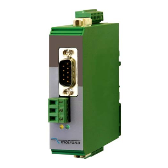
Signal Splitter and Incremental Converter for
Input:
sin / cos 1 Vpp
SV 210
• Encoder inputs sin+, sin-, cos+, cos-, ref+, ref- with 1 Vpp format
• Two sine-cosine output channels with the same signal format
• Two incremental outputs, each with differential signal format A, /A, B, /B, Z, /Z ,
individually adjustable to either TTL/RS422 level or HTL (10-30 V) level
• Suitable for input frequencies up to 500 kHz
• 17 - 30 VDC power supply and auxiliary output 5 V or 24 V for encoder supply
SV21001a_e.doc / Jul-10
interface
SV 210
Sine-Cosine Encoders
Operating Instructions
motrona GmbH
Zwischen den Wegen 32
78239 Rielasingen - Germany
Tel. +49 (0)7731-9332-0
Fax +49 (0)7731-9332-30
info@motrona.com
www.motrona.com
Out 1
sin / cos 1Vpp
Out 2
incremental
A, /A, B, /B, Z, /Z
5 - 30 V
Out 3
sin / cos 1Vpp
Out 4
incremental
A, /A, B, /B, Z, /Z
5 - 30 V
Page 1 / 11
Advertisement
Table of Contents

Related Manuals for Motrona SV 210


Summary of Contents for Motrona SV 210
- Page 1 78239 Rielasingen - Germany Tel. +49 (0)7731-9332-0 Fax +49 (0)7731-9332-30 control – motion – interface info@motrona.com www.motrona.com SV 210 Signal Splitter and Incremental Converter for Sine-Cosine Encoders Out 1 sin / cos 1Vpp Input: Out 2 sin / cos 1 Vpp...
- Page 2 • - Errors and omissions excepted – General instructions for cabling, screening and grounding can be found in the SUPPORT section of our website http://www.motrona.com Version: Description: SV21001a_July 2010/af/hk First edition SV21001a_e.doc / Jul-10...
-
Page 3: Table Of Contents
Table of Contents 1. Application...................... 4 2. Connection Diagram ..................6 2.1. Power Supply (X6) ....................6 2.2. Connection of the Sine-Cosine Encoder (X5) ............7 2.3. The Sine-Cosine Outputs (X1 und X3) ..............7 2.4. The Incremental Outputs (X2 und X4) ..............8 3. -
Page 4: Application
1. Application The SV 210 encoder splitter has been designed for clean and trouble-free distribution of the output signals of sine-cosine type encoders to several target units. Since on the output site the unit provides both, sine-cosine outputs and incremental outputs, it is suitable for use with target units with either sine or incremental inputs. - Page 5 Typical application example of the SV 210 signal splitter: Speed feedback (sin-cos) Servo drive Control unit sin-cos Counter A / B Motor with sin-cos encoder (HTL) Follower drive A, /A, B, /B (TTL) SV21001a_e.doc / Jul-10 Page 5 / 11...
-
Page 6: Connection Diagram
2. Connection Diagram For wiring of the sinusoidal signals the unit provides 3 Sub-D-9 connectors (X1, X3, and X5). For all other connections 3 screw terminal strips are available (X2, X4, and X6). Output 2 (incremental) Output 1 (sin-cos 1 Vpp) Sub-D-9 female 9 8 7 6 5 4 3 2 1 Screw terminal strip 9-pos. -
Page 7: Connection Of The Sine-Cosine Encoder (X5)
2.2. Connection of the Sine-Cosine Encoder (X5) The encoder can be connected via the front Sub-D-9 connector marked X5 (male connector on unit side, female connector on the encoder cable). Only encoders with differential sine-cosine signals of 1 Vpp can be used (0.8 Vpp - 1.2 Vpp). At any time the signals sin+/sin- and cos+/cos- must be available. -
Page 8: The Incremental Outputs (X2 Und X4)
2.4. The Incremental Outputs (X2 und X4) On the terminal strips X2 and X4 the encoder information is available with a differential square wave format. All incremental outputs use push-pull drivers. When position 2 (Com+) of the corresponding terminal strip is unconnected, the output level is automatically adapted to TTL / RS422 format. -
Page 9: The Front Leds
3. The Front LEDs The green LED is lit whenever the power supply of the unit is on. The yellow Led indicates the presence of encoder input signals. With slow motion, the LED will blink with every input impulse. With higher speeds the blinking will pass over into a continuous glowing with reduced brightness. -
Page 10: Dimensions
4. Dimensions 102 (4.016”) 22.5 (0.886”) 91 (3.583”) Side view Front view Top view SV21001a_e.doc / Jul-10 Page 10 / 11... -
Page 11: Technical Specifications
5. Technical Specifications Power supply Vin 17 V - 30 VDC Supply current approx. 70 mA (unloaded) Aux. encoder power output 5,2V / 150 mA (or according to remote feed-in) Max. frequency 500 kHz Signal inputs 6 symmetric differential sin/cos - inputs (Terminating resistors 3 x 120 ohms inbuilt) (sin+, sin-, cos+, cos-, ref+, ref-), Signal level 0,8 Vpp - 1,2 Vpp,...
Need help?
Do you have a question about the SV 210 and is the answer not in the manual?
Questions and answers