Table of Contents
Advertisement
Quick Links
Code : SEA 314
ASSEMBLY MANUAL
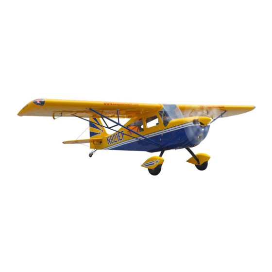
Specifications:
Wingspan--------------- 122.0 in (310.0 cm).
Wing area--------------- 2487.8 sq.ins (160.5 sq.dm).
Weight------------------- 26.4-27.4 lbs (12.5-13.0kg).
Length------------------- 84.6 in (215.0 cm).
Engine/Motor size----- 60-85cc gasoline.
Radio--------------------- 7 channels with 9 servos.
1
Advertisement
Table of Contents

Related Manuals for Seagull Models Decathlon 60-85cc-3D


Summary of Contents for Seagull Models Decathlon 60-85cc-3D
-
Page 1: Specifications
Code : SEA 314 ASSEMBLY MANUAL Specifications: Wingspan--------------- 122.0 in (310.0 cm). Wing area--------------- 2487.8 sq.ins (160.5 sq.dm). Weight------------------- 26.4-27.4 lbs (12.5-13.0kg). Length------------------- 84.6 in (215.0 cm). Engine/Motor size----- 60-85cc gasoline. Radio--------------------- 7 channels with 9 servos. - Page 2 DECATHLON 60-85cc-3D INTRODUCTION Thank you for choosing the DECATHLON 60-85cc-3D ARTF by SG MODELS . The DECATHLON 60-85cc-3D was designed with the intermediate/advanced sport fly- er in mind. It is a semi scale airplane which is easy to fly and quick to assemble. The air- frame is conventionally built using balsa, plywood to make it stronger than the av- erage ARTF, yet the design allows the aeroplane to be kept light.
- Page 3 WINGTIP BULBS KIT CONTENTS SEA314 DECATHLON 60-85cc-3D Please see below pictures. 1. Fuselage 2. Wing set (2) 3. Tail set (2) 4. Canopy 5. Cowling 6. Wing tube 7. Pilot 8. landing gear 9. Fuel tank 10. Tail wheel 11. Pushrod set 12.
- Page 4 Instruction Manual. DECATHLON 60-85cc-3D...
- Page 6 Instruction Manual. DECATHLON 60-85cc-3D INSTALL THE AILERONS CONTROL HORN Fiberglass control horn Epoxy.
- Page 7 Place the servo between the mounting blocks and space it from the hatch. Use a pencil to mark the mounting hole loca- tions on the blocks. Use drill bit in a pin vise to drill the mout- ing holes in the blocks. Epoxy.
- Page 8 Instruction Manual. DECATHLON 60-85cc-3D Use dental floss or heatshrunk tube to secure the connection so they cannot be- come unplugged. Secure the servo to the aileron hatch us- ing Phillips screwdriver and the screws provided with the servo. Apply 1-2 drops of thin C/A to each of the mounting tabs.
- Page 9 3x10mm INSTALLING THE FLAP PUSHROD 130mm. AILERON PUSHROD INSTALLATION 130mm. 150mm. Attach the flap servo to the flap servo cover. Center the flap servo (or set the values to 0 for both up and down) and in- stall the servo arm perpendicular to the servo centerline.
- Page 10 Instruction Manual. DECATHLON 60-85cc-3D Route the servo lead for the flap servo out at the root of the wing. Connect the flap Use a pin vise and 3/32-inch (2mm) drill servo to the radio system. With the radio bit to clear the paint from the flap control system on, place the flap servo into posi- horn.
- Page 11 3x10mm Fit the flap linkage cover into position. Set the flap control at the transmitter to Check the operation of the flap to make the down flap position. Adjust the flap sure the cover does not interfere with the travel at the transmitter until it matches flap linkage.
- Page 12 Instruction Manual. DECATHLON 60-85cc-3D INSTALLING LANDING GEAR Locate items necessary to install Sprin Landing Gear.
- Page 13 Collar. M3x4mm. 4x25mm. 3x15mm.
- Page 14 Instruction Manual. DECATHLON 60-85cc-3D INSTALLING THE FUSELAGE SERVOS Because the size of servos differ, you may need to adjust the size of the precut opening in the mount. The notch in the sides of the mount allow the servo lead to pass through.
- Page 15 Elevator servo. Rudder servo.
- Page 16 Instruction Manual. DECATHLON 60-85cc-3D Switch. INSTALLING THE ENGINE SWITCH Elevator servo arm . Rudder servo arm. Trim and cut. INSTALLING THE RECEIVER SWITCH Install the switch into the precut hole in the side, in the fuselage. 3/32” Hole. Switch. INSTALLING THE STOPPER ASSEMBLY Trim and cut.
- Page 17 Using a modeling knife, cut one length of With the stopper assembly in place, the weighted pick-up should rest away from the silicon fuel line. Connect one end of the rear of the tank and move freely inside the line to the weighted fuel pick up and the tank.
- Page 18 Instruction Manual. DECATHLON 60-85cc-3D Balsa wood. Epoxy. Vent tube. Fuel pick up tube. Fuel fill tube. Connect the lines from the tank to the en- gine and muffler. The vent line will con- nect to the muffler and the line from the clunk tothe carburetor.
- Page 19 180mm 6x90mm...
- Page 20 Instruction Manual. DECATHLON 60-85cc-3D Ignition Modude. THROTTLE SERVO ARM INSTALLATION Install adjustable servo connector in the servo arm as same as picture below:...
- Page 21 Move the throttle stick to the closed posi- tion and move the carburetor to closed. Use a 2.5mm hex wrench to tighten the screw that secures the throttle pushrod wire. Make sure to use threadlock on the screw so it does not vibrate loose. Reinstall the servo horn by sliding the connector over the pushrod wire.
- Page 22 Instruction Manual. DECATHLON 60-85cc-3D...
- Page 23 Use a drill and drill bit to drill the holes for the cowl mounting screws. Make sure the cowl position is correct before drill- ing each hole. Install the muffler and muffler extension onto the engine and make the cutout in the cowl for muffler clearance.
- Page 24 Instruction Manual. DECATHLON 60-85cc-3D Nylon screw 4x25mm. ELECTRIC POWER CONVERSION Locate the items neccessary to install the electric power conversion included with your model. Recommend the items necessary to install the electric power conversion parts included with your model.
- Page 25 - Motor: 80cc - 195 KV - Propeller: 27 x 10 - ESC: 200A - 12S- 14S Lipo 18mm.
- Page 26 Instruction Manual. DECATHLON 60-85cc-3D Attach the electric motor box to the fire- wall centered with the cross lines drawn on the electric motor box and firewall. Using M6x25mm to secure the motor box to the firewall. Please see pictures below.
- Page 27 Blind nut. 6mm. Attach the motor mount to the front of the electric motor box using four 4mm blind nut, four M6x25mm hex head bolts to se- cure the motor. Please see picture shown. 6x25mm. Then, use 8mm drill bit to enlarge the holes on the electric motor box.
- Page 28 Instruction Manual. DECATHLON 60-85cc-3D 6x25mm Balsa stick. Speed control. Epoxy. Attach the speed control to the side of the motor box using two-sided tape and tie wraps. Connect the appropriate leads from the speed control to the mo- tor. Make sure the leads will not interfere...
- Page 29 INSTALLING THE SPINNER Install the spinner backplate, propeller and spinner cone. Battery. The propeller should not touch any part of the spinner cone. If it does, use a sharp modeling knife and carefully trim away the spinner cone where the propel- ler comes in contact with it.
- Page 30 Instruction Manual. DECATHLON 60-85cc-3D Install the elevator control horn using the same method as same as the elevator control horns. Epoxy. INSTALL ELEVATOR CONTROL HORN...
- Page 31 INSTALL NAIL HINGE RUDDER Test fit the hinges into the rudder, and then the hinges into the tail. Ensure that the hinge pockets line up, and that the hinges move freely. Epoxy. Plug in the power cord...
- Page 32 Instruction Manual. DECATHLON 60-85cc-3D Epoxy. INSTALL RUDDER CONTROL HORN Install the elevator control horn using the same method as same as the aileron control horns. 20mm...
- Page 33 INSTALLING WING TUBE VERTICAL STABILIZE Parts requirement.See pictures below. Epoxy.
- Page 34 Instruction Manual. DECATHLON 60-85cc-3D 3x20mm.
- Page 35 3x20mm. Horizontal Vertical INSTALLING HORIZONTAL Stabilizer. Stabilizer. STABLLIZER 4x12mm.
- Page 36 Instruction Manual. DECATHLON 60-85cc-3D 4x12mm. 4x12mm. Elevator control horn. 135mm. 155mm. ELEVATOR PUSHROD HORN INSTALLATION Install the elevator control horn using the 155mm. same method as with the aileron control horns. Position the elevator control horn on the both side of elevator.
- Page 37 100mm. 120mm. Elevator pushrod. Rudder. MOUNTING THE TAIL WHEEL Locate items necessary to install tail wheel.
- Page 38 Instruction Manual. DECATHLON 60-85cc-3D...
- Page 39 3x20mm.
- Page 40 Instruction Manual. DECATHLON 60-85cc-3D 3x20mm. 3x6mm. 3x20mm.
- Page 41 3x6mm.
- Page 42 Instruction Manual. DECATHLON 60-85cc-3D 3x6mm.
- Page 43 3x6mm. INSTALLING THE WING STRUT Parts requirement.See pictures below.
- Page 44 Instruction Manual. DECATHLON 60-85cc-3D...
- Page 46 Instruction Manual. DECATHLON 60-85cc-3D...
- Page 48 Instruction Manual. DECATHLON 60-85cc-3D...
- Page 49 INSTALL THE WINDOW Parts requirement.See pictures below.
- Page 50 Instruction Manual. DECATHLON 60-85cc-3D Epoxy. Epoxy.
- Page 52 Instruction Manual. DECATHLON 60-85cc-3D INSTALLATION PILOT AND CANOPY Locate items necessary to install pilot and canopy.
- Page 53 A scale pilot is included with this ARF. The Pilot included fitting well to the cockpit. (or you can order others scale pilot figures made by SG Models. They are available at SG Models distributors.) If you are going to install a pilot figure, please use a sanding bar to sand the base of the figure so that it is flat.
- Page 54 Instruction Manual. DECATHLON 60-85cc-3D Epoxy. Epoxy.
- Page 55 Epoxy canopy onto the fuselage. Trace around the canopy and onto the fuselage using a epoxy. ATTCHMENT WING-FUSELAGE Attach the aluminiu, thube into fuselage. Epoxy.
- Page 56 Instruction Manual. DECATHLON 60-85cc-3D...
- Page 57 INSTALLING TOW RELEASE FOR SAIL PLANE. Screw the aero-tow mechanism into the hole just behind the canopy, and apply thread- lock flid to prevent the coupling and nut from working loose. The aluminium part must be shortened enough so that the clevis can move freely, adjust the rods accordingly...
- Page 58 Instruction Manual. DECATHLON 60-85cc-3D It is best to operate the aero-tow release mechanism using a momentary switch mounted on the joystick. Th servo travel must be set accordingly. INSTALLING NEEDED ANTEN Parts requirement.See pictures below.
- Page 59 *If possible, first attempt to balance the APPLY THE DECALS model by changing the position of the receiver battery and receiver. If you are If all the decals are precut and ready to unable to obtain good balance by doing stick.
-
Page 60: Instruction Manual
Instruction Manual. DECATHLON 60-85cc-3D 60-100mm 60-100mm 50-70mm Fuselage 50-70mm 40-70mm Wing 40-70mm 40mm 140mm... - Page 61 A) Plug in your radio system per the 2) Check every bolt and every glue manufacturer’s instructions and turn eve- joint in the DECATHLON 60-85cc-3D rything on. to ensure that everything is tight and well bonded. B) Check the elevator first. Pull back on the elevator stick.
- Page 62 Instruction Manual. DECATHLON 60-85cc-3D If you have any queries, or are interested in our products, please feel free to contact us Factory : 12/101A - Hamlet 4 - Le Van Khuong Street - Dong Thanh Ward - Hoc Mon District - Ho Chi Minh City - Viet Nam.
Need help?
Do you have a question about the Decathlon 60-85cc-3D and is the answer not in the manual?
Questions and answers