Table of Contents
Advertisement
Quick Links
Advertisement
Table of Contents

Related Manuals for KEB combicontrol PCC C5


Summary of Contents for KEB combicontrol PCC C5
- Page 1 COMBICONTROL Instruction Manual PCC C5 07/2007...
- Page 2 The safety and warning reference specified in this manual is not exhaustive. The manual and the information contained in it is made with care. KEB don´t accept a guarantee for misprint or other errors or resulting damages.
-
Page 3: Table Of Contents
Multi-function switch/button S1 .................16 File system ......................17 Field bus interface ProfiBus DP ............18 Basic data of the C5-PROFIBUS interface ............18 The raw data of the KEB-PROFIBUS-DP interface ...........19 Parameters of the PROFIBUS interface .............21 Software ....................22 Programming system CoDeSys .................22 Parameterizing system COMBIVIS ..............22... -
Page 4: Description Of The Unit
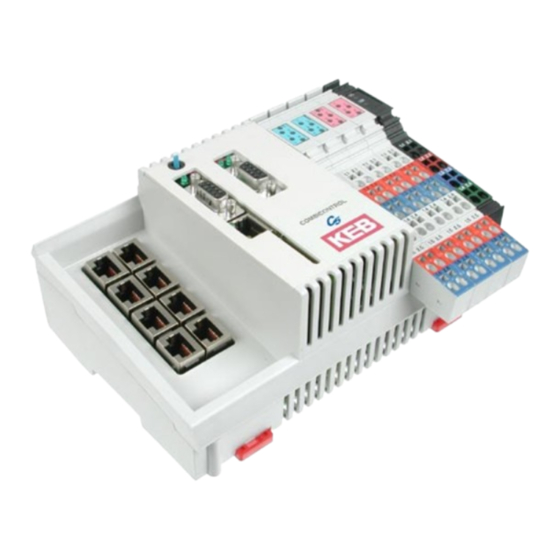
Description of the unit Application KEB COMBICONTROL C5 is a programmable control with direct connection upto 8 KEB frequency inverters/servo axes of the series F5. The connection to the axes is created as HSP5/485. All axes can be operated directly and synchronously with an inexpensive operator with this fast, reliable connection. -
Page 5: Technical Data
Axis interface Type HSP5/485 Connector RJ-45, 8-pole, screened Cable Cat 5, 100 m max. Speed 38,4…250 kBaud Connection to KEB F5 inverter/servo, process data transmission, communication channel GB - 5... -
Page 6: Accessories
COMBICONTROL Ethernet interface 09C5xxx-xxxx 19C5xxx-xxxx Type IEEE 802.3 IEEE802.3 10Base-T 10/100BaseTx Connector RJ-45, 8-pole, screened Speed 10 MBaud 10/100 MBaud autocrossover Connection to CoDeSys (programming sys- tem, debugging, visualization) Connection to COMBIVIS (control and axis adjustment, Scope) Connection to any devices (Socket-APi) Serial interface 09C5xxx-xxxx 19C5xxx-xxxx... -
Page 7: Basic Module With Drive Interfaces
COMBIVIS or the control program. HSP5/485 interfaces to the inverter/servo axes Up to eight KEB COMBIVERT F5 can be connected via the terminals X1A to X1H. The connection occurs via reliability RS485 cables, which can be up to 100 m long. A shielded standard cable with RJ-45 connector is used on the control side and appropriate operator on the frequency inverter/servo. -
Page 8: View Of The Inverter Interfaces X1A
COMBICONTROL %IW40+41 %ID20 1. Word (32 Bit) of axis5 %QD20 1. Word (32 Bit) to axis 5 %IW42 2. Word (16 Bit) of axis5 %QW42 2. Word (16 Bit) to axis 5 %IW43 3. Word (16 Bit) of axis5 %QW43 3. Word (16 Bit) to axis 5 %IW48+49 %ID24 1. -
Page 9: Hsp5 Operator With Screw Terminal (00F5060-9001)
COMBICONTROL 2.2.3 HSP5 Operator with screw terminal (00F5060-9001) X6E Name Description TXD- Transmission signal- TXD+ Transmission signal+ RXD- Receive signal- No cables may be connected RXD+ Receive signal+ to terminal VCC. High voltage EnTXD- Handshake transmission signal- EnTXD+ Handshake transmission signal+ can destroy the interface in the EnRxD- Handshake receive signal- control. -
Page 10: Adapter Cable Hsp5 Interface Operator
COMBICONTROL 2.2.5 Adapter cable HSP5 interface operator Screw terminal: Color see below C5 PCC Signal TXD+ TXD- GND RXD+ RXD- GND EnTXD+ EnTXD- X1A…H Operator Signal RXD+ RXD- GND TXD+ TXD- GND EnRxD+ EnRxD- Color see below RJ45 connection: Color see below C5 PCC Signal TXD+ TXD- GND RXD+ RXD- GND EnTXD+ EnTXD-... -
Page 11: In-/Output Module
COMBICONTROL In-/output module X2A X2B X2C X2D X2U Overload display of the outputs Control LED's for Voltage US (control unit) Control-LED´s light, if input or Voltage UM (in-/outputs) output is set Digital input 5 Digital output 0 Digital input 4 Digital output 1 Digital input 1 Digital output 4... -
Page 12: Voltage Supply (X2U)
COMBICONTROL Voltage supply (X2U) Voltage supply for the control (US) Voltage supply for the inputs and outputs (UM) %IX1.0 Condition of the supply voltage in/outputs (UM) %IW1 %IX1.1 Is set in case of overload at one or several outputs %IX1.2…%IX1.15 not assigned ���... -
Page 13: Digital Inputs (X2A And X2B)
COMBICONTROL Digital inputs (X2A and X2B) 8 digital inputs 0...7 (2 blocks) ��� ��� Condition of the digital �� �� %IX0.0…%IX0.7 (%IB1) %IW0 inputs 0…7 %IX0.8…%IX0.15 (%IB0) not assigned ��� ��� ��� ��� ��� ��� ��� ��� ��� ��� �� ��... -
Page 14: The Operating Unit
COMBICONTROL The operating unit Name Function Addition View Multi function switch/but- Clear Stop LD1 Run-LED green LD2 Error LED LD3 Ethernet LAN /100 yellow LD4 Ethernet Link / Data green LD5 Fieldbus Data green LD6 Fieldbus Ready green X6A Serial interface COMBIVIS X6B Ethernet interface COMBIVIS/... -
Page 15: Ethernet Interface (X6B)
COMBICONTROL Ethernet interface (X6B) The standardized 10/100 base-T interface supports the protocols TCP/IP and UDP/IP. The following ports have these functions: The CoDeSys port is adjusted to 1200 (as standard). The port can be changed with para- meter Et.03. The control program is processed here by means of CoDeSys (only TCP/IP possible). -
Page 16: Multi-Function Switch/Button S1
COMBICONTROL Multi-function switch/button S1 The multi function switch/button is constructed as follows: clear (button) stop/reset run (switch) The button S1 is assigned with the following functions Activity Function Stop --> Run Program is started Run --> Stop Programm is stopped, all variables are resetted (reset warm) Stop -->... -
Page 17: File System
COMBICONTROL File system The file system consists of an internal built-in flash memory (drive C:) and an optionally external plugged-in memory card (drive A:). Access can occur via CoDeSys or directly from the program of the control. Internal flash memory This memory is accessed as drive C: and the boot project can be stored, which is automatically loaded and started when switching on. -
Page 18: Field Bus Interface Profibus Dp
COMBICONTROL Field bus interface ProfiBus DP Basic data of the C5-PROFIBUS interface The PROFIBUS interface of the C5 control is corresponding to the PROFIBUS-DP standard (DIN 19245 Part3). Now the PROFIBUS DP standard is also specified in the international standard, IEC 61158 as type 3. The present quick guide shall only describe the basic pro- perties. -
Page 19: The Raw Data Of The Keb-Profibus-Dp Interface
• Process output data: Data, which are transmitted non-addressed from master to slave. • Process input data: Data, which are transmitted non-addressed from slave to master. The KEB C5 PROFIBUS-interface adjusts itself flexible to the configuration preset by the master. By this way it is possible •... - Page 20 ��� ��� ��� ��� ��� ��� ��� ��� ��� ��� ��� ��� Coding of the raw data from the KEB-DP interface to DP master Parametrizing channel confirmation Process input data Legend Low-Byte High-Byte ���� ���������� ���������� High-Word �� ����� ��...
-
Page 21: Parameters Of The Profibus Interface
COMBICONTROL Parameters of the PROFIBUS interface The parameters serve for the configuration of the PROFIBUS interface. The parameters are addressed via PROFIBUS by means of index (16 bit) and subindex (8 bit). Name Fieldbus Comm Axis Meaning Serves for change-over of the PROFIBUS communication between each devices, which can be addressed by the control. -
Page 22: Software
The axis control is programmed with the programming system CoDeSys of the company 3S- Software (www.3s-software.com). This programming software is free-available in the Internet. A KEB target information file (TNF) for the control is available as accessories, which contains all required hardware specifications. A library with firmware functional modules is further con- tained for access to the periphery (axes, real-time clock, switch, LED, file system). -
Page 23: Parameter Description
COMBICONTROL Parameter description 6.3.1 Runtime and error monitoring The ru-parameters serve for monitoring of the program flow. ru.00 Status Address 0200h Program status no prog no program loaded prog OK program loaded prog corrupt program checksum error Control status Program runs Stop Program stopped breakpoint... -
Page 24: Ethernet Parameter
COMBICONTROL 6.3.2 Ethernet parameter The following parameters contain the values, which are needed for the communication via the Ethernet interface. et.00 MAC address Address 0300h The MAC address (Media Access Control) is formed of 6 byte. The first three bytes contain the manufacturer's code (00-08-FA). -
Page 25: Real-Time Clock
COMBICONTROL data port password et.09 Address 0309h This parameter defines the write protection password for the COMBIVIS data port. The programming of the password occurs only via the serial interface. Then this password must be entered here again for write access via the data port. Error message "operation not possible"... -
Page 26: Process Image
COMBICONTROL seconds rc.01 Address 0401h This parameter displays the seconds in a range of 0...59. Writing on this parameter ad- justs the seconds. date rc.02 Address 0402h This parameter displays the date in a DD-MM format. Writing on this parameter adjusts the date. -
Page 27: Userdefinition Parameter
COMBICONTROL pi.07 axis outdata 3 Address 0507h Displays the value of the third process-output data (16 Bit) of the axes. Set 0 is for the data of axis 1, set 1 for the axis 2, etc. pi.08 fieldbus indata Address 0508h Displays the value of the Fieldbus-input data. -
Page 28: System Parameter
COMBICONTROL ud.06 error counters tx Address 0806h This parameter counts the errors during the transmission to each individual axis. Set 0 displays the errors of axis 1, set 1 of axis 2 etc. ud.07 fieldbus comm axis Address 0807h This parameter displays the axis, on which the field bus accesses to by parameter com- munication. -
Page 29: Debugging
This parameter determines the Fieldbus address. sy.07 baud rate 66019II Address 0007h The baud rate for the KEB DIN 66019II protocol is adjusted with this parameter. sy.10 Address 000Ah Display of the unit type. The following parameters serve for the operation of the inverter scope part of COMBIVIS. -
Page 30: System Variables
COMBICONTROL System variables The following system variables are available in the PLC program: SYSAXISMODE Displays the axes control mode adjusted via the function block 'tSetModes'. SYSERRORAXIS Displays the failed monitored or cyclic/synchronous operated axes. In case of failure of an axis the red error LED at the operating unit is switched on and the event "excpt_axis_error"... - Page 31 COMBICONTROL GB - 31...
- Page 32 • mail: www.keb.de info@keb.de KEB (UK) Ltd. KEB Antriebstechnik GmbH & Co. KG 6 Chieftain Buisiness Park, Morris Close Wildbacher Str. 5 • D–08289 Schneeberg Park Farm, Wellingborough GB-Northants, NN8 6 XF fon: +49 3772 67-0 • fax: +49 3772 67-281 fon: +44 1933 402220 •...
Need help?
Do you have a question about the combicontrol PCC C5 and is the answer not in the manual?
Questions and answers