
Related Manuals for Satel ETHM-1


Summary of Contents for Satel ETHM-1
- Page 1 TCP/IP Communication Module ETHM-1 Firmware version 1.05 ethm1_en 03/13 SATEL sp. z o.o. ul. Schuberta 79 80-172 Gdańsk POLAND tel. + 48 58 320 94 00 info@satel.pl www.satel.eu...
- Page 2 Changes, modifications or repairs not authorized by the manufacturer shall void your rights under the warranty. The SATEL's goal is to continually upgrade the quality of its products, which may result in alterations of their technical specifications and firmware. The current information on the introduced modifications is available on our website.
-
Page 3: Typical Applications
1 General The ETHM-1 module enables the INTEGRA, INTEGRA Plus and VERSA alarm control panels to communicate via the Ethernet (TCP/IP) network. The data transmission is encrypted using an advanced algorithm based on 192-bit key. The module firmware can be updated using an application available on the www.satel.eu website. -
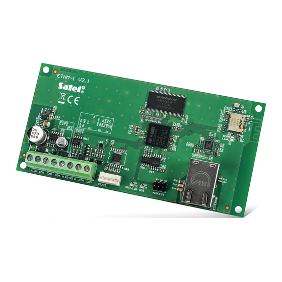
Page 4: Electronics Board
ETHM-1 SATEL 3 Electronics Board Fig. 1. Module electronics board. terminals: - power input (+12 V DC). +12V - common ground. - tamper input (NC). If not used, it should be connected to the common ground. A_RS485_B - unused terminals. - Page 5 INTEGRA with PIN5 type socket: PIN5/PIN5 (see Fig. 2) INTEGRA / INTEGRA Plus with RJ type socket: RJ/PIN5 (see Fig. 3) VERSA: PIN5/RJ-TTL Fig. 2. Schematic of the cable used to connect the RS-232 ports of ETHM-1 module and INTEGRA control panel with PIN5 socket.
-
Page 6: Setting The Address
ETHM-1 SATEL Fig. 3. Schematic of the cable used to connect the RS-232 ports of ETHM-1 module and INTEGRA / INTEGRA Plus control panel with RJ type socket. 7. Power-up the alarm system. 8. Start the device identification function in the control panel (see the installer manual for the respective control panel). -
Page 7: Module Settings
The IP address assigned to the module can be read in the LCD keypad with the user function available in the T submenu: ESTS INTEGRA / INTEGRA Plus: IP/MAC ETHM-1; VERSA: E . (for a detailed description of the function please refer to the XPANDER VER user manual for the control panel). - Page 8 ETHM-1 SATEL Fig. 4. D X program: settings of the ETHM-1 module connected to INTEGRA control LOAD panel. DloadX DloadX->ETHM connection [Connect DloadX] – if this option is enabled, connection with the control panel can be initiated via the TCP/IP network from the D X program.
- Page 9 (available to the service and administrators). HANGE OPTIONS Fig. 5. D X program: settings of the ETHM-1 module connected to VERSA control panel. LOAD GuardX / Java [Connect GuardX] – if this option is enabled, connection with the control panel via...
- Page 10 The other parameters are global ING TEST (they apply to all the ETHM-1 modules connected to the control panel) and can be programmed: keypad: by means of functions available in the PING submenu (S...
- Page 11 5.2 Virtual keypad settings During communication with the control panel through the ETHM-1 module, you can use a virtual keypad to operate and program the alarm system. For the INTEGRA / INTEGRA Plus control panel, settings of the virtual keypad are configurable. Parameters and options of...
-
Page 12: Macro Commands
ETHM-1 SATEL Fig. 6. D X program: settings of the virtual keypad available in the G X program, web LOAD UARD browser or mobile phone. 5.3 Macro commands The M KPD2 PRO application allows control of the INTEGRA / INTEGRA Plus alarm... - Page 13 SATEL ETHM-1 5.3.1 Parameters and options Fig. 7. D X program: macro command groups programmed for the M KPD2 PRO LOAD OBILE application. Macro command group – the list of macro commands which will be displayed on touching the macro key. You can define 4 macro command groups.
- Page 14 ETHM-1 SATEL command at once (if the A option is enabled, authorization by UTHORIZATION REQUIRED means of a code will be necessary). Fig. 8. D X program: macro commands programmed for M KPD2 PRO application. LOAD OBILE Command – control panel executed function which ca n be assigned to a macro command.
- Page 15 SATEL ETHM-1 Using the M KPD2 PRO application you can control the KNX system, provided OBILE that the INT-KNX module is connected to the control panel. 5.3.2 Defining the macro commands 1. Click on the "Definition" tab. 2. Click on the "New macro" button. A new macro command will appear in the list.
- Page 16 Ethernet (TCP/IP) network, please refer to the control panel programming manuals. 6.1 GuardX program Communication between the G X program and the control panel through the ETHM-1 UARD module can be established in two ways: 1. Initiating connection from the G X program.
-
Page 17: Web Browser
key for data encryption (identical to that programmed in the module for communication with the G X program); UARD address of the ETHM-1 module, if communication is to be initiated from the G UARD program. Fig. 10. G X program: settings for communication via Ethernet (TCP/IP) network. - Page 18 Fig. 12. Virtual keypad available in the web browser. 1. Start the web browser. 2. In the address field, enter the ETHM-1 module IP address, and then press ENTER. If a port different than 80 has been programmed in the module settings for communication with the web browser, indicate the port number after entering the address followed by a colon.
-
Page 19: Mobile Phone
KPD2 application in your cell phone. The application is OBILE OBILE available for downloading at the www.satel.eu site (select the application suitable for your mobile phone), from the "Google play" internet store (Android system devices) or from the "App Store" (iOS system devices). -
Page 20: Specifications
ETHM-1 SATEL Establishing communication – 6.3.4 KPD2 OBILE Touch the name of alarm system. The virtual keypad will be displayed, which can be used for operating and programming the alarm system. Fig. 13. Virtual keypad available in the M KPD2 application (phone with Android OBILE operating system).
Need help?
Do you have a question about the ETHM-1 and is the answer not in the manual?
Questions and answers