Satel ETHM-1 Plus Manual
Ethernet communication module
Hide thumbs
Also See for ETHM-1 Plus:
- Manual (39 pages) ,
- Quick installation manual (25 pages) ,
- Quick installation manual (4 pages)
Table of Contents
Advertisement
Quick Links
Download this manual
See also:
Manual
Advertisement
Table of Contents

Subscribe to Our Youtube Channel
Related Manuals for Satel ETHM-1 Plus


Summary of Contents for Satel ETHM-1 Plus
- Page 1 Ethernet communication module ETHM-1 Plus Firmware version 2.00 ethm1_plus_en 07/14 SATEL sp. z o.o. ul. Budowlanych 66 80-298 Gdańsk POLAND tel. + 48 58 320 94 00 info@satel.pl www.satel.eu...
- Page 2 FreeRTOS is used in this device (www.freertos.org). The SATEL's goal is to continually upgrade the quality of its products, which may result in alterations of their technical specifications and firmware. The current information on the introduced modifications is available on our website.
-
Page 3: Table Of Contents
Defining macro commands................16 6.4.4 Exporting macro file..................20 Remote programming / operating of control panel via Ethernet........21 GuardX program...................... 21 7.1.1 Configuring ETHM-1 Plus module ..............21 7.1.2 Configuring G X program ................21 UARD 7.1.3 Initiating connection from G X program ............. -
Page 4: General
ETHM-1 Plus SATEL 1 General The ETHM-1 Plus module enables the INTEGRA Plus, INTEGRA and VERSA alarm control panels to communicate via the Ethernet network. The data transmission is encrypted by means of an advanced algorithm based on 192-bit key. -
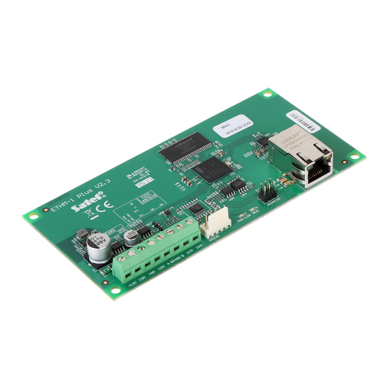
Page 5: Electronics Board
SATEL ETHM-1 Plus 3 Electronics Board Fig. 1. Module electronics board. terminals: - +12 V DC power input. +12V - common ground. - tamper input (NC) – if not used, it should be shorted to common ground. A RS485 B - terminals provided for future applications (RS-485). -
Page 6: Module Connected To Integra / Integra Plus Control Panel
ETHM-1 Plus SATEL Address Pins status Table 1. 4.1 Module connected to INTEGRA / INTEGRA Plus control panel Set an address in the module within the range: from 0 to 3, if it is connected to INTEGRA 24 or INTEGRA 32 control panel, ... - Page 7 VERSA: PIN5/RJ-TTL The above mentioned cables are available in SATEL's product offering. Fig. 3. Wiring diagram of the cable connecting RS-232 ports of ETHM-1 Plus module and INTEGRA control panel with PIN5 connector socket. Fig. 4. Wiring diagram of the cable connecting RS-232 ports of ETHM-1 Plus module and...
-
Page 8: Configuring
ETHM-1 Plus SATEL 6 Configuring The module can be configured via the control panel, using a keypad or a computer with X program installed on it. LOAD 6.1 Module parameters and options 6.1.1 Module connected to INTEGRA / INTEGRA Plus control panel You can configure parameters and options of the module using: ... - Page 9 LOAD HANGE OPTIONS service and administrators). Fig. 5. D X program: parameters and options of ETHM-1 Plus module connected to LOAD INTEGRA / INTEGRA Plus control panel. GuardX / Java GuardX [Connect GuardX] – if this option is enabled, it is possible to initiate connection with the control panel via Ethernet from the G X program.
- Page 10 LOAD SATEL server Connection via Satel server [SATEL server] – if this option is enabled, communication with the module can be effected via the SATEL server. For communication vie the SATEL server, you do not need to additionally configure the network device through which the module connects to the public network.
-
Page 11: Module Connected To Versa Control Panel
Information MAC – module hardware address. ID – identifier assigned to the module for the purposes of communication via the SATEL server. IP – local address / public address of the module. 6.1.2 Module connected to VERSA control panel Parameters and options of the module can be configured using: ... - Page 12 X program. LOAD Fig. 6. D X program: parameters and options of the ETHM-1 Plus module connected to LOAD VERSA control panel. PING test Address to test [PING] – address of the device to which a ping command to test communication is to be sent by the module.
-
Page 13: Virtual Keypad
SATEL ETHM-1 Plus 6.2 Virtual keypad The virtual keypad allows you to operate and program the alarm system in much the same way as using a physical keypad. 6.2.1 Module connected to INTEGRA / INTEGRA Plus control panel You can use the virtual keypad in the D... -
Page 14: Module Connected To Versa Control Panel
ETHM-1 Plus SATEL D X program: ”Structure” window ”Hardware” tab ”Keypads” branch ”DloadX LOAD (RS-232)” item. Settings of the virtual keypad available in the G X program, web browser or mobile UARD phone can be programmed using: LCD keypad: S S... -
Page 15: Groups
Instead of a file with macro OBILE commands defined for the ETHM-1 Plus module, you can load a file with macro commands defined for the LCD keypad. The data related to macro commands are stored in the module memory. Before you start defining the macro commands, click on the "Read"... -
Page 16: Definitions
KPD-2 P application or imported to OBILE another ETHM-1 Plus module or to a INT-KSG keypad (i.e. macro commands can be copied between the devices). Import from file – click on the button to import macro commands from a file. - Page 17 SATEL ETHM-1 Plus Change – click on the button to save the changes to the command parameters which were made after adding the command to the list (otherwise, the changes made will not be saved). Delete – click on the button to remove the highlighted command from the list.
-
Page 18: Defining Macro Commands
ETHM-1 Plus SATEL Outputs ON – highlight the outputs which are to be activated (double-click on the field designated by the output number). Outputs OFF – highlight the outputs which are to be deactivated (double-click on the field designated by the output number). - Page 19 SATEL ETHM-1 Plus 3. Click on the "New macro" button. A new macro command will appear on the list. 4. Enter a name for the new macro command. 5. If the macro command is to be run without entering the code by the user, enter a code having appropriate authority level.
- Page 20 ETHM-1 Plus SATEL 8. If the macro command is to be run immediately on tapping the macro key, enable the option (in such a case, only this one macro command is to be assigned to UTOEXECUTE the group). 9. Click on the button and select the function the new macro command is to execute.
- Page 21 SATEL ETHM-1 Plus 11. Click on the "Add" button. A new command will appear on the list of commands assigned to the macro command. You can still modify parameters of the command after clicking on it (having made the changes, click on the "Change" button).
-
Page 22: Exporting Macro File
ETHM-1 Plus SATEL 16. Click on the "Add macro" button. A list of all defined macro commands will be displayed. 17. Click on a macro command to add it to the group. The macro command will be put in the tree under the group. -
Page 23: Remote Programming / Operating Of Control Panel Via Ethernet
X program (Fig. 11), click on the "Configuration" button. UARD A window will be displayed, in which, in "TCP/IP" tab (Fig. 12), you should program: ETHM-1 Plus module address, if communication is to be initiated from G X program, UARD ... -
Page 24: Initiating Connection From G X Program
3. In the window that will be displayed after establishing communication, enter the code of administrator / user of the control panel. 7.2 Web browser 7.2.1 Configuring ETHM-1 Plus module Enable the WWW option. Program the key for data encryption during communication with the JAVA application in... - Page 25 SATEL ETHM-1 Plus 2. In the address field, enter the IP address of ETHM-1 Plus module, and then press ENTER. If a port other than 80 is to be used for communication between the module and the web browser, the address entered must be followed by a colon and the port number.
-
Page 26: Mobile Phone
The OBILE OBILE OBILE application can be downloaded at www.satel.eu (select the application suitable for your mobile phone), from the internet stores "Google play" (Android system devices) or "App Store" (iOS system devices). Having installed the application, enter: ... -
Page 27: Specifications
SATEL ETHM-1 Plus Fig. 15. M KPD-2 application (Android system phone): virtual keypad. OBILE 8 Specifications Supply voltage ....................12 V DC ±15% Standby current consumption ..................70 mA Maximum current consumption..................80 mA Environmental class according to EN50130-5 ................. II Operating temperature range..................-10...+55 °C Maximum humidity ......................
Need help?
Do you have a question about the ETHM-1 Plus and is the answer not in the manual?
Questions and answers