Satel ETHM-1 Plus Manual
Ethernet communication module
Hide thumbs
Also See for ETHM-1 Plus:
- Manual (46 pages) ,
- Quick installation manual (25 pages) ,
- Manual (27 pages)

Related Manuals for Satel ETHM-1 Plus


Summary of Contents for Satel ETHM-1 Plus
- Page 1 Ethernet communication module ETHM-1 Plus Firmware version 2.05 ethm1_plus_en 07/18 SATEL sp. z o.o. ul. Budowlanych 66 80-298 Gdańsk POLAND tel. + 48 58 320 94 00 www.satel.eu...
- Page 2 FreeRTOS is used in this device (www.freertos.org). SATEL's goal is to continually upgrade the quality of its products, which may result in some changes of their technical specifications and firmware. The current information on the introduced modifications is available on our website.
-
Page 3: Table Of Contents
Initiating connection from keypad (through control panel) ........ 31 7.1.4 Initiating connection by SMS message............. 31 7.1.5 Establishing connection via the SATEL server ..........32 Web browser ......................32 INTEGRA CONTROL application ................33 7.3.1 Configuring the settings in INTEGRA CONTROL application (Android) ... 34 7.3.2... -
Page 4: General
Ethernet network. The data transmission is encrypted by means of an advanced algorithm based on 192-bit key. You can connect the INT-GSM module to the ETHM-1 Plus module. This will allow GPRS to be used as a backup communication path and enable dual path reporting. -
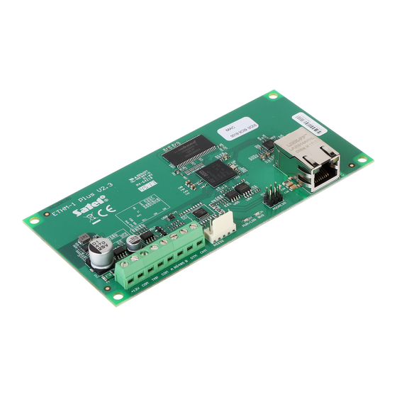
Page 5: Electronics Board
- tamper input (NC) – if not used, it should be shorted to common ground. A RS485 B - RS-485 port for connecting INT-GSM module. The INTG-GSM module is supported if the ETHM-1 Plus module is connected to the INTEGRA Plus / INTEGRA control panel with firmware version 1.18 or newer. -
Page 6: Setting Address
ETHM-1 Plus SATEL 4 Setting address To set an address, you must place jumpers across the ADDRESS pins. Table 1 shows how to use jumpers in order to set a specific address ( - jumper on; - jumper off). Address Pins status Table 1. - Page 7 INTEGRA with connector socket of RJ / INTEGRA Plus type: RJ/PIN5 (Fig. 4) VERSA: PIN5/RJ-TTL The above mentioned cables are available in SATEL's product offering. Fig. 3. Wiring diagram of the cable connecting RS-232 ports of ETHM-1 Plus module and INTEGRA control panel with PIN5 connector socket.
-
Page 8: Configuring The Settings
ETHM-1 Plus SATEL Fig. 4. Wiring diagram of the cable connecting RS-232 ports of ETHM-1 Plus module and INTEGRA / INTEGRA Plus control panel with RJ type connector socket. 6 Configuring the settings The module settings differ, depending on the control panel to which the module is connected. - Page 9 SATEL ETHM-1 Plus SMS messaging [SMS messaging] – if this option is enabled, the INT-GSM module can send notifications about alarm system events in the form of SMS messages. Fig. 5. DLOADX program: settings of the module connected to INTEGRA / INTEGRA Plus control panel (module is identified as “ETHM-1”).
- Page 10 Fig. 6. DLOADX program: settings of the module connected to INTEGRA / INTEGRA Plus control panel (module is identified as “ETHM+GSM” – INT-GSM module is connected to ETHM-1 Plus module). DLOADX Communication with DLOADX [Connect DLOADX] – if this option is enabled, connection can be established between the DLOADX program and the alarm control panel via the module.
- Page 11 SATEL ETHM-1 Plus DLOADX server [DLOADX IP] – address of the computer running the DLOADX program. If the computer is not in the same local network, it must be a public address. You can enter either the IP address or the domain name.
- Page 12 DLOADX program: “Structure” window “Hardware” tab “Keypads” branch. SATEL server Connection via Satel server [SATEL server] – if the option is enabled, the module connects to the SATEL server and the communication via the SATEL server with the control panel can be established (Connection Setup Service).
-
Page 13: Int-Gsm Functions
SATEL server. You can read the QR code by using a mobile device or export to the file and transmit to the users. The QR code facilitates configuring the INTEGRA CONTROL application settings. - Page 14 ETHM-1 Plus SATEL Fig. 7. DLOADX program: “IP filter” tab. Filtering by IP address In the IP A field, enter the network address from which establishing connection with DDRESS the module (control panel) is to bed possible. The option on the right-hand side of the SUBNET field must not be selected.
- Page 15 SATEL ETHM-1 Plus Filtering by subnet 1. Select the option. Description of one of the IP A fields will change to SUBNET DDRESS . From now on, the IP A and S fields constitute a pair. UBNET MASK DDRESS UBNET MASK 2.
-
Page 16: User Functions
ETHM-1 Plus SATEL 6.1.4 User functions If the INTEGRA CONTROL application is used in the mobile device, the virtual keypad allows you to quickly start user functions after entering the code and pressing an arrow key. Fig. 8. Program DLOADX: “User functions definition” tab. -
Page 17: Macro Commands
SATEL ETHM-1 Plus Fig. 9. DLOADX program: parameters and options of the virtual keypad available in GUARDX program, web browser or mobile device. 6.1.6 Macro commands The INTEGRA CONTROL application allows to control the alarm system by means of macro commands, thus making it possible to quickly and easily run a number of different functions by touching just a few keys. - Page 18 This method allows you to use macro commands defined e.g. for the INT-TSG keypad in the INTEGRA CONTROL application. Instead of a file with macro commands defined for the ETHM-1 Plus module, you can load a file with macro commands defined for the LCD keypad.
- Page 19 SATEL ETHM-1 Plus Name – name of the macro command group (up to 16 characters in two lines, up to 8 characters in the line). Do not enter the name if it is not to be displayed. Icon – icon of a group of macro commands. Click to display the list of available icons.
- Page 20 ETHM-1 Plus SATEL controlled by using macro commands or the status of partitions which are armed by a macro command. Show name – if this option is enabled, the macro command name will be displayed. Fig. 11. DLOADX program: “Definitions” tab.
- Page 21 SATEL ETHM-1 Plus 0 - fully armed; 1 – fully armed+bypasses; 2 – armed without interior; 3 - armed without interior and without entry delay). Disarming – highlight the partitions which are to be disarmed (double-click on the field designated by the partition number).
- Page 22 ETHM-1 Plus SATEL Defining macro commands 1. Click the “Read” button to read the macro command related data from the module. 2. Click on the “Definitions” tab. 3. Click the “New macro” button. A new macro command will appear on the list.
- Page 23 SATEL ETHM-1 Plus 6. If the macro command is to be unavailable when any of the partitions managed by the keypad is armed, enable the D option. ISABL IF ARMED 7. If the macro command is to be available without entering the group, enable the option.
- Page 24 ETHM-1 Plus SATEL 11. If the macro command name is to be displayed, enable the S option. HOW NAME 12. Click the button and select the function the new macro command is to execute. 13. Configure the command parameters. 14. Click the “Add” button. A new command will appear on the list of commands assigned to the macro command.
- Page 25 SATEL ETHM-1 Plus 15. Repeat the steps 12-14, if you want to add next commands. 16. Click the “Groups” tab. 17. Click on the group you want to edit. 18. Enter the group name, if it is to be displayed.
-
Page 26: Module Connected To Versa Control Panel
ETHM-1 Plus SATEL 21. Click on a macro command to add it to the group. The macro command will be put in the tree under the group. 22. Click the “Write” button to write the macro command related data to the module. -
Page 27: Lan
SATEL server. You can read the QR code by using a mobile device or export to the file and transmit to the users. The QR code facilitates configuring the VERSA CONTROL application settings. - Page 28 ETHM-1 Plus SATEL The IP address assigned to the module can be read in the LCD keypad using the . user function available in the T submenu. For a detailed description ODULE VER ESTS of the function please refer to the user manual for the control panel.
-
Page 29: Messaging
SATEL ETHM-1 Plus Tries no. before trouble [PING tries] – the number of failed communication tests (the module received no answer to the ping command sent), after which the trouble will be reported. If value 0 is programmed, the communication test is disabled. -
Page 30: Remote Programming / Operating Of Control Panel Via Module
7 Remote programming / operating of control panel via module The module enables communication with the control panel over Ethernet. If the INT-GSM module is connected to the ETHM-1 Plus module, the backup communication path is GPRS (the module is identified as “ETHM+GSM”). -
Page 31: Guardx Program
GUARDX program module must have a public IP address. 3. Initiating connection by SMS message. The computer with GUARDX program must have a public IP address. The INT-GSM module must be connected to the ETHM-1 Plus module. - Page 32 Select the “ETHM-1 MAC” variant. ETHM-1 MAC – hardware address of Ethernet module. ETHM-1 ID – individual ID number assigned to the module by the SATEL server. Server key – a string of up to 12 alphanumeric characters (digits, letters and special characters) used for data encryption during communication between the control panel and the computer with GUARDX.
-
Page 33: Initiating Connection From Guardx Program
SATEL ETHM-1 Plus Fig. 18. GUARDX program: “Satel server” tab in “Connection” window. 7.1.2 Initiating connection from GUARDX program Required settings of the module: programmed number of TCP port used for communication. Required settings of the GUARDX program for direct communication with the module: ... -
Page 34: Establishing Connection Via The Satel Server
It is recommended that the 32-bit version of Java Virtual Machine be installed. 1. Start the web browser. 2. In the address field, enter the IP address of ETHM-1 Plus module, and then press ENTER. If a port other than 80 is to be used for communication between the module and the web browser, the address entered must be followed by a colon and the port number. -
Page 35: Integra Control Application
SATEL ETHM-1 Plus TCP port number (identical to that programmed in the module for communication with the JAVA application in the web browser – except where communication occurs through a network device on which redirection to another port takes place), Fig. -
Page 36: Configuring The Settings In Integra Control Application (Android)
SATEL downloaded from the internet store “Google play” (Android system devices) or “App Store” (iOS system devices). On the www.satel.eu website, you will find links to the locations from which the applications can be downloaded. The INTEGRA CONTROL app can connect directly to the ETHM-1 Plus module (the module must have a public IP address) or establish connection via the SATEL server (Connection Setup Service –... -
Page 37: Configuring The Settings In Integra Control Application (Ios)
(you can define settings for multiple alarm systems). 4. Specify the method of communication. The default settings provide for communication directly with the Ethernet module. If the application is to connect via the SATEL server, enable the “Server Satel” option. -
Page 38: Establishing The Communication
ETHM-1 Plus SATEL The alarm system user can check the module network address, MAC address and ID using the LCD keypad (IP/MAC/IMEI/ID user function available in the T submenu ESTS – see the control panel user manual). Fig. 22. INTEGRA CONTROL application (iOS system): screen with communication settings before entering data. -
Page 39: Specifications
SATEL ETHM-1 Plus Fig. 23. INTEGRA CONTROL application (Android system): virtual keypad. 8 Specifications Supply voltage ....................12 V DC ±15% Standby current consumption ..................70 mA Maximum current consumption..................80 mA Environmental class according to EN50130-5 ................. II Operating temperature range..................-10...+55 °C Maximum humidity ......................
Need help?
Do you have a question about the ETHM-1 Plus and is the answer not in the manual?
Questions and answers