Satel ETHM-1 Plus Manual
Ethernet communication module
Hide thumbs
Also See for ETHM-1 Plus:
- Manual (46 pages) ,
- Quick installation manual (25 pages) ,
- Manual (27 pages)

Related Manuals for Satel ETHM-1 Plus


Summary of Contents for Satel ETHM-1 Plus
- Page 1 Ethernet communication module ETHM-1 Plus Firmware version 2.03 ethm1_plus_en 06/16 SATEL sp. z o.o. ul. Budowlanych 66 80-298 Gdańsk POLAND tel. + 48 58 320 94 00 www.satel.eu...
- Page 2 FreeRTOS is used in this device (www.freertos.org). SATEL's goal is to continually upgrade the quality of its products, which may result in some changes of their technical specifications and firmware. The current information on the introduced modifications is available on our website.
-
Page 3: Table Of Contents
7.1.2 Initiating connection from GUARDX program ........... 27 7.1.3 Initiating connection from keypad (through control panel) ........ 28 7.1.4 Establishing connection via the SATEL server ..........28 Web browser ......................28 7.2.1 ETHM-1 Plus module settings ................28 7.2.2 Configuring computer ..................29 7.2.3... -
Page 4: General
ETHM-1 Plus SATEL 1 General The ETHM-1 Plus module enables the INTEGRA Plus, INTEGRA and VERSA alarm control panels to communicate via the Ethernet network. The data transmission is encrypted by means of an advanced algorithm based on 192-bit key. -
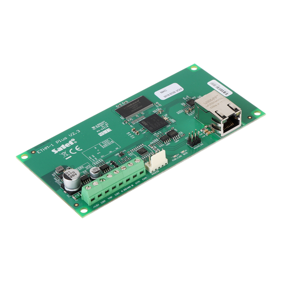
Page 5: Electronics Board
SATEL ETHM-1 Plus 3 Electronics Board Fig. 1. Module electronics board. terminals: +12V - +12 V DC power input. - common ground. - tamper input (NC) – if not used, it should be shorted to common ground. A RS485 B - terminals provided for future applications (RS-485). -
Page 6: Module Connected To Integra / Integra Plus Control Panel
ETHM-1 Plus SATEL Address Pins status Table 1. 4.1 Module connected to INTEGRA / INTEGRA Plus control panel Set an address in the module within the range: • from 0 to 3, if it is connected to INTEGRA 24 or INTEGRA 32 control panel, •... - Page 7 VERSA: PIN5/RJ-TTL The above mentioned cables are available in SATEL's product offering. Fig. 3. Wiring diagram of the cable connecting RS-232 ports of ETHM-1 Plus module and INTEGRA control panel with PIN5 connector socket. Fig. 4. Wiring diagram of the cable connecting RS-232 ports of ETHM-1 Plus module and...
-
Page 8: Configuring The Settings
ETHM-1 Plus SATEL 6 Configuring the settings The module settings differ, depending on the control panel to which the module is connected. 6.1 Module connected to INTEGRA / INTEGRA Plus control panel 6.1.1 Module parameters and options You can configure parameters and options of the module using: •... - Page 9 (available HANGE OPTIONS to service and administrators). Fig. 5. DLOADX program: parameters and options of ETHM-1 Plus module connected to INTEGRA / INTEGRA Plus control panel. GUARDX / Java GUARDX [Connect GUARDX] – if this option is enabled, it is possible to initiate connection with the control panel via Ethernet from the GUARDX program.
- Page 10 DLOADX program: “Structure” window “Hardware” tab “Keypads” branch. SATEL server Connection via Satel server [SATEL server] – if this option is enabled, the control panel connects to the SATEL server via the Ethernet module, while the SATEL server makes it possible to establish communication with the control panel (Connection Establishing Service).
-
Page 11: Ip Filter
Information MAC – module hardware address. ID – identifier assigned to the module for the purposes of communication via the SATEL server. The ID number is assigned automatically by the SATEL server. IP – local address / public address of the module. - Page 12 ETHM-1 Plus SATEL Fig. 6. DLOADX program: “IP filter” tab. IP Address – if the option is disabled: the network address from which connection SUBNET with the Ethernet module can be established. If the option is enabled: the IP SUBNET address used for defining the subnet from which connection with the Ethernet module can be established.
-
Page 13: User Functions
SATEL ETHM-1 Plus Filtering by subnet 1. Select the option. Description of one of the IP A fields will change to SUBNET DDRESS . From now on, the IP A and S fields constitute a pair. UBNET MASK DDRESS UBNET MASK 2. -
Page 14: Virtual Keypad
ETHM-1 Plus SATEL Fig. 7. Program DLOADX: “User functions definition” tab. 6.1.4 Virtual keypad The virtual keypad allows you to operate and program the alarm system in much the same way as using a physical keypad. You can use the virtual keypad in the DLOADX and... -
Page 15: Macro Commands
“GUARDX/MobileKPD” item “Macro Commands” tab). Defined macro commands can be automatically downloaded by the INTEGRA CONTROL / KPD-2 P application after establishing connection with the ETHM-1 Plus module. OBILE Macro commands can be loaded into the application without establishing connection with the module. - Page 16 ETHM-1 Plus SATEL file with macro commands defined for the ETHM-1 Plus module, you can load a file with macro commands defined for the LCD keypad. The data related to macro commands are stored in the module memory. Before you start defining the macro commands, click on the “Read”...
- Page 17 KPD-2 P OBILE application or imported to another ETHM-1 Plus module or to a INT-KSG keypad (i.e. macro commands can be copied between the devices). Import from file – click on the button to import macro commands from a file.
- Page 18 ETHM-1 Plus SATEL Code – the code which is to be used for authorization when executing commands contained in the macro command. The code must have an appropriate authority level for execution of such commands to be possible. The code is presented as a string of asterisks.
- Page 19 SATEL ETHM-1 Plus Type – the telegram type. Value – the value that will be inserted in the telegram (parameter available for some types of the telegram). Priority – telegram priority (if two elements of the bus start transmitting simultaneously, the telegram with higher priority will be sent first).
- Page 20 ETHM-1 Plus SATEL 4. Enter a name for the new macro command. 5. If the macro command is to be run without entering the code by the user, enter a code having appropriate authority level. 6. If running a macro command is to be each time preceded by user authorization, enable the A option.
- Page 21 SATEL ETHM-1 Plus 9. Click on the button and select the function the new macro command is to execute. 10. Configure the command parameters. 11. Click on the “Add” button. A new command will appear on the list of commands assigned to the macro command.
- Page 22 ETHM-1 Plus SATEL 12. Repeat the steps 9-11, if you want to add next commands. 13. Click on the “Groups” tab. 14. Click on the group you want to edit. 15. Enter the group name. 16. Click on the “Add macro” button. A list of all defined macro commands will be displayed.
-
Page 23: Module Connected To Versa Control Panel
SATEL ETHM-1 Plus 17. Click on a macro command to add it to the group. The macro command will be put in the tree under the group. 18. Click on the “Write” button to write the macro command related data to the module. - Page 24 DLOADX program via Ethernet. ETHM Fig. 11. DLOADX program: parameters and options of the ETHM-1 Plus module connected to VERSA control panel. Obtain IP address automatically (DHCP) [DHCP] – if this option is enabled, the module will automatically download data on IP address, subnet mask and gateway from the DHCP server (in such a case, you do not have to program these parameters).
- Page 25 Ethernet from the DLOADX program. Satel server [SATEL server LAN] – if this option is enabled, the control panel connects to the SATEL server via the Ethernet module, while the SATEL server makes it possible to establish communication with the control panel (Connection Establishing Service).
-
Page 26: Messaging
ETHM-1 Plus SATEL Get Date and Time from a time server [Time from srvLAN] – if the option is enabled, the control panel clock will be synchronized with the time server once a day. For communication with the time server, the DNS server must be used. -
Page 27: Remote Programming / Operating Of Control Panel Via Ethernet
Ethernet network, please refer to the control panel programming manuals. 7.1 GUARDX program Connection between the GUARDX program and the control panel via the ETHM-1 Plus module can be established using one of the following ways: 1. Connection initialized from the GUARDX program. If communication takes place in a wide area network, the Ethernet module must have a public IP address. -
Page 28: Configuring The Guardx Program Settings
ETHM-1 Plus SATEL 3. Establishing connection via the SATEL server (Connection Establishing Service). The control panel can be operated from any location. No public IP address is required for the control panel or the computer with GUARDX program. 7.1.1 Configuring the GUARDX program settings To configure the settings related to communication with the alarm system, click on the “Configuration”... -
Page 29: Initiating Connection From Guardx Program
ETHM-1 MAC – hardware address of Ethernet module. ETHM-1 ID – individual identification number of the Ethernet module for the purpose of communication via the SATEL server. Fig. 17. GUARDX program: “Satel server” tab in “Connection” tab. 7.1.2 Initiating connection from GUARDX program ETHM-1 Plus module settings •... -
Page 30: Initiating Connection From Keypad (Through Control Panel)
• Enter the data encryption key (identical to that in the module). • Enter the MAC address of the ETHM-1 Plus module. • Enter the ID number of the ETHM-1 Plus module (identifier assigned to the module for the purposes of communication via the SATEL server). -
Page 31: Configuring Computer
7.2.3 Establishing the communication 1. Start the web browser. 2. In the address field, enter the IP address of ETHM-1 Plus module, and then press ENTER. If a port other than 80 is to be used for communication between the module and the web browser, the address entered must be followed by a colon and the port number. -
Page 32: Mobile Device
(you can define settings for multiple alarm systems). 2. Specify the method of communication. The default settings provide for communication via the SATEL server. If the application is to connect directly to the Ethernet module, touch the screen in the “Communication way” area and change the settings. - Page 33 SATEL ETHM-1 Plus Fig. 20. INTEGRA CONTROL application (Android system): “Add control panel” screen before entering data.
- Page 34 SATEL server. 1. Enter the MAC address of the ETHM-1 Plus module. 2. Enter the ID number of the ETHM-1 Plus module (identifier assigned to the module for the purposes of communication via the SATEL server).
- Page 35 Fig. 22. INTEGRA CONTROL application (Android system): “Add control panel” screen with an example of settings for communication directly with the module. 1. Enter the ETHM-1 Plus module address. 2. Enter the TCP port number, if it is to be different from 7091.
-
Page 36: Configuring The Settings In Integra Control Application (Ios)
(you can define settings for multiple alarm systems). 4. Specify the method of communication. The default settings provide for communication directly with the Ethernet module. If the application is to connect via the SATEL server, enable the “Server Satel” option. -
Page 37: Ethm-1 Plus Module Settings
Configuring the settings for communication via SATEL server 1. Enter the MAC address of the ETHM-1 Plus module. 2. Enter the ID number of the ETHM-1 Plus module (identifier assigned to the module for the purposes of communication via the SATEL server). -
Page 38: Specifications
ETHM-1 Plus SATEL Fig. 24. INTEGRA CONTROL application (Android system): virtual keypad. OBILE 1. Using phone keys, select an alarm system from the list. 2. Select: “Options” “Start”. 3. Elements of the virtual keypad will be shown on the display. - Page 39 SATEL ETHM-1 Plus Operating temperature range .................. -10...+55 °C Maximum humidity ......................93±3% Dimensions ......................68 x 140 mm Weight ..........................64 g...
Need help?
Do you have a question about the ETHM-1 Plus and is the answer not in the manual?
Questions and answers