Satel ACCO-KP2 Installer Manual
Access control module
Hide thumbs
Also See for ACCO-KP2:
- Quick installation manual (9 pages) ,
- User manual (21 pages) ,
- Manual (4 pages)

Related Manuals for Satel ACCO-KP2


Summary of Contents for Satel ACCO-KP2
- Page 1 ACCO-KP2 Access control module ACCO INSTALLER MANUAL Firmware version 1.00 acco-kp2_i_en 03/22 SATEL sp. z o.o. • ul. Budowlanych 66 • 80-298 Gdańsk • POLAND tel. +48 58 320 94 00 www.satel.eu...
- Page 2 Keil RTX5 – under Apache 2.0 license (https://www2.keil.com/mdk5/cmsis/rtx) 1wIP – under BSD license (https://savannah.nongnu.org/projects/1wip). SATEL aims to continually improve the quality of its products, which may result in changes in their technical specifications and software. Current information about the changes being introduced is available on our website.
-
Page 3: Table Of Contents
5.1.1 Installing and connecting the ACCO-KLCDR keypad ........11 5.1.2 Installing and connecting the ACCO-SCR keypad ..........13 5.1.3 Connecting the SATEL reader ................14 5.1.4 Connecting the Wiegand reader ............... 15 5.1.5 Connecting the DALLAS iButton reader ............15 5.2 Connecting activators and door sensors .............. -
Page 4: Introduction
ACCO-KP2 1. Introduction The ACCO-KP2 module is used to control access to a single door. This manual describes the access control module (electronics version 3.3) and how to install it. This manual also provides information on the devices that work with the module and how to connect them. - Page 5 LEDs to indicate: the status of communication between module and computer, the power supply status, the receipt of identifier information, the relay status, the status of outputs. Connector for SATEL power supply unit.
-
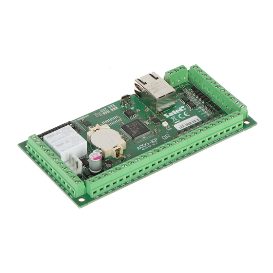
Page 6: Electronics Board
SATEL ACCO-KP2 3. Electronics board Fig. 1. Electronics board in ACCO-KP2 door controller module. APS connector for a SATEL power supply unit (e.g. APS-412). DIP-switches for setting the module address (see “Address setting” p. 6). LEDs (see “Description of LEDs”). -
Page 7: Description Of Leds
ACCO-KP2 SATEL – connecting reader B: data (0) [SIG1B], – connecting reader B: data (1) [SIG2B], – reader B presence control [TMPB], – programmable input 1, – programmable input 2, – programmable input 3, IN10 – programmable input 4, IN11 –... -
Page 8: Address Setting
SATEL ACCO-KP2 ON – power ON; OFF – power OFF. O1…O12 LEDs indicate the status of outputs. Address setting If the module is to work in the access control system, you must set an individual address in the module. To set the address, use the DIP-switches on the module electronics board. The switches have numbers assigned to them. -
Page 9: Acco-Scr Keypad With Proximity Card Reader
ACCO-KP2 SATEL LEDs to indicate the door / module status. Backlit keys. Built-in sounder. Tamper protection against enclosure opening and removal from the wall. Fig. 3. ACCO-KLCDR keypad. 4.1.2 ACCO-SCR keypad with proximity card reader Keys for entering the code. -
Page 10: Emm And Cz-Emm2 Proximity Card Readers
SATEL ACCO-KP2 Fig. 4. ACCO-SCR keypad. 4.1.3 CZ-EMM and CZ-EMM2 proximity card readers Support for cards, key tags and other 125 kHz passive transponders. Outgoing data format: EM-Marin. Bicolor LED to indicate the door / reader status. -
Page 11: Emm3 And Cz-Emm4 Proximity Card Readers
ACCO-KP2 SATEL 4.1.4 CZ-EMM3 and CZ-EMM4 proximity card readers Support for cards, key tags and other 125 kHz passive transponders. Outgoing data format: EM-Marin or Wiegand 26. Two LEDs to indicate the door / reader status. Built-in sounder. -
Page 12: Third-Party Wiegand Readers
SATEL ACCO-KP2 Fig. 7. CZ-DALLAS reader. 4.1.6 Third-party Wiegand readers Supported Wiegand transmission formats: 26 bit – parity bit (even) + card number (24 bits) + parity bit (odd); byte order: from MSB to LSB; 32 bit – card number (32 bits) without parity check; byte order: from MSB to LSB;... -
Page 13: Installing And Connecting The Terminals
ACCO-KP2 SATEL The reader / LCD keypad working as terminal A is treated by the module as the entry terminal. The reader / LCD keypad working as terminal B is treated by the module as the exit terminal. Fig. 8. Example of access control installation. - Page 14 – a correct address is set in the LCD keypad. Fig. 9. Method of connecting the LCD keypad to the ACCO-KP2 module. The +G3 output is used as an example. You can use the +G1...+G4 outputs. Setting the LCD keypad address The module supports LCD keypads with addresses 0 and 1.
-
Page 15: Installing And Connecting The Acco-Scr Keypad
5. Close the enclosure and secure it with the screw. 6. Connect the keypad wires to the module as shown in Table 2. 7. You can connect the yellow wire (BELL output) to the module input programmed as “Bell signal”. ACCO-KP2 terminals Wire Description Terminal A Terminal B +G1…+G4... -
Page 16: Connecting The Satel Reader
LED OUT2 OUT6 gray red LED OUT3 OUT7 disabling reader brown OUT4 OUT8 operation white presence control IN8…IN12 OC type output (BELL) violet (input programmed as “Bell signal”) [CZ-EMM4] Table 3. Method of connecting the SATEL reader to the module. -
Page 17: Connecting The Wiegand Reader
Connect the Wiegand reader as shown in Table 4. The length of cable connecting the reader with the module should not exceed 30 m. For detailed description of how to install the reader, please refer to its manual. ACCO-KP2 terminals Function Terminal A Terminal B +G1…+G4... -
Page 18: Connecting Activators And Door Sensors
SATEL ACCO-KP2 5.2 Connecting activators and door sensors 1. Connect the device which is to activate the door to the relay output. Depending on the device type, use the NO or NC terminal. It is not recommended that the door actuator be powered from the same source as the module. -
Page 19: Connecting The Power Supply And Starting The Module
6. Module in the access control system Access control system without control panel (ACCO) You can connect the ACCO-KP2 modules using the RS-485 bus in order to build the ACCO access control system. The system may comprise up to 255 modules. The data necessary for access control is stored in the memory of each module, which allows the modules to work as stand-alone devices. -
Page 20: Access Control System With The Acco-Nt Control Panel (Acco Net)
Access control system with the ACCO-NT control panel (ACCO NET) You can connect the ACCO-KP2 modules to the ACCO-NT control panel using the RS-485 bus in order to build the ACCO NET access control system. The ACCO NET system may include any number of access control panels. -
Page 21: Acco-Scr Keypad With Proximity Card Reader
ACCO-KP2 SATEL Reader transmit frequency .................... 125 kHz Supported card standards ....... UNIQUE, EM4001, EM4002, EM4003, EM4102 Maximum humidity ......................93±3% Dimensions ....................140 x 126 x 26 mm Weight ..........................236 g 7.3 ACCO-SCR keypad with proximity card reader Supply voltage ....................
Need help?
Do you have a question about the ACCO-KP2 and is the answer not in the manual?
Questions and answers