Arbor Technology EmCORE-i89M2 User Manual
3.5” compact board
Hide thumbs
Also See for EmCORE-i89M2:
- Quick installation manual (11 pages) ,
- Quick installation manual (10 pages) ,
- Quick installation manual (10 pages)
Table of Contents
Advertisement
Quick Links
Advertisement
Table of Contents

Related Manuals for Arbor Technology EmCORE-i89M2


Summary of Contents for Arbor Technology EmCORE-i89M2
- Page 1 EmCORE-i89M2 3.5” Compact Board User’s Manual Version 1.2 2019.09...
- Page 2 Revision History Version Date Description 2018.01 Initial release 1.1. Packing List: Remove driver CD 1.3. Driver Installation: Revise installation instructions 1.4. Specifications: Revise specification descriptions of CPU, Ethernet controller and graphic interface : Revise PWR1 description 2.1. Block Diagram 2019.03 2.2.
-
Page 3: Table Of Contents
Contents Preface .....................iii Copyright Notice ............... iii Declaration of Conformity ............iii CE ..................iii RoHS ................. iv SVHC / REACH ..............iv About This User’s Manual ............v Warning ..................v Replacing the Lithium Battery ........... v Technical Support ..............v Warranty ................... - Page 4 Contents 3.2.9 S5 RTC Wake Settings ..........53 3.2.10 CSM Configuration ..........54 3.3 Chipset ................55 3.3.1 Graphics Configuration ..........57 3.3.2 Memory Configuration ..........59 3.3.3 LCD Control ............60 3.3.4 PCI Express Configuration ........61 3.3.5 USB Configuration ..........62 3.4 Security ................63 3.5 Boot ..................64 3.6 Save &...
-
Page 5: Preface
Preface Copyright Notice All Rights Reserved. The information in this document is subject to change without prior notice in order to improve the reliability, design and function. It does not represent a commitment on the part of the manufacturer. Under no circumstances will the manufacturer be liable for any direct, indirect, special, incidental, or consequential damages arising from the use or inability to use the product or documentation, even if advised of the possibility of such damages. -
Page 6: Rohs
RoHS ARBOR Technology Corp. certifies that all components in its products are in compliance and conform to the European Union’s Restriction of Use of Hazardous Substances in Electrical and Electronic Equipment (RoHS) Directive 2002/95/EC. -
Page 7: About This User's Manual
Preface of SVHC (Substances of Very High Concern) in (EC) 1907/2006 (REACH --Registration, Evaluation, Authorization, and Restriction of Chemicals) regulated by the European Union. All substances listed in SVHC < 0.1 % by weight (1000 ppm) About This User’s Manual This user’s manual provides general information and installation instructions about the product. -
Page 8: Warranty
Preface Warranty This product is warranted to be in good working order for a period of two years from the date of purchase. Should this product fail to be in good working order at any time during this period, we will, at our option, replace or repair it at no additional charge except as set forth in the following terms. -
Page 9: Chapter 1 Introduction
Chapter 1 Introduction Chapter 1 - Introduction... -
Page 10: Packing List
Before starting with the installation, make sure the following items are shipped. If any item appears damaged or is missing, contact your vendor immediately: 1 x EmCORE-i89M2 3.5” Compact Board with Cooler 1 x Quick Installation Guide 1.2. Ordering Information ®... -
Page 11: Driver Installation
Introduction 1.3. Driver (6.6A) Installation To install the drivers, please visit our website at www.arbor-technology.com and download the driver pack from the product page. The driver path is listed as below: Windows 7 & Windows 10 64-bit Chipset \i89X\Chipset\Chipset_10.1.1.13_Public Audio \i89X\Audio\7687_PG436_Win10_Win8.1_Win8_Win7_WHQLx64 \i89X\Ethernet \i89X\Graphic\IntelR Graphics Driver Production Version... -
Page 12: Specifications
Introduction 1.4. Specifications Form Factor 3.5" Compact Board Soldered onboard 6th Generation Intel® Quad Core™ Processor i5-6442EQ 1.9GHz (base)/2.7GHz (Turbo); i7-6822EQ 2.0GHz 2.0GHz (Base)/2.8GHz(Turbo) ® Chipset Intel PCH QM170 1 x DDR4 SO-DIMM socket, supporting Memory 2133/1866MHz SDRAM up to 16GB BIOS AMI UEFI BIOS Watchdog Timer... - Page 13 Introduction 1.77A @+12V with i5-6442EQ (Typical) Power Consumption 1.82A @+12V with i7-6822EQ (Typical) Operating Temp. -40 ~ 85°C (-40 ~ 185ºF) Operating Humidity 10 ~ 95% @ 85°C (non-condensing) Dimensions (L x W) 146 x 102 mm (5.7" x 4.0") - 5 -...
-
Page 14: Board Dimensions
Introduction 1.5. Board Dimensions 8,84 142,77 9,15 Unit:mm - 6 -... -
Page 15: Installing The Memory
Introduction 1.6 Installing the Memory Side notch Latch knob Latch section Latch claw Latch arm Polarizing key To install the Memory module, locate the Memory SO-DIMM slot on the board and perform as below: 1. Adjust the socket polarizing key and the board key to the same direction. 2. - Page 16 This page is intentionally left blank. - 8 -...
-
Page 17: Chapter 2 Installation
Chapter 2 Installation Chapter 2 - Installation... -
Page 18: Block Diagram
Installation 2.1. Block Diagram PWR1 PTN3460 Dual Chnnels DDI (eDP) LVDS1 12V DC input eDP to LVDS 24-bit LVDS LVDS connector transmitter 6th/7th Generation CHRONTEL Intel® Core CH7511B Dual Chnnels LVDS2 DDI (DP) i7-6822EQ (25W)/ eDP to LVDS 24-bit LVDS LVDS connector transmitter i5-6442EQ (25W) -
Page 19: Jumpers & Connectors Quick Reference
Installation 2.2. Jumpers & Connectors Quick Reference Jumpers Jumper Description ➊ Clears/keeps CMOS JBAT1 ➋ Sets the AT/ATX mode JPWR1 ➌➍ Sets the power voltage for LVDS1, 2 JVLCD1, 2 ➎➏ Sets the inverter voltage for LVDS1, 2 JINV1, 2 Connectors Connector Description... -
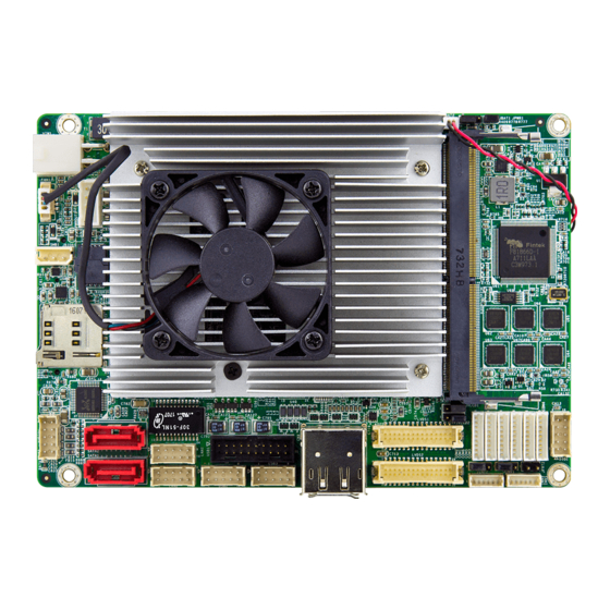
Page 20: Jumpers & Connectors Location
Installation 2.3. Jumpers & Connectors Location Board Top PWROUT1 JPWR1 JBAT1 VIN1 FAN1 SMB1 JVLCD1 JVLCD2 SIM1 LVDS1 LAN1 20 21 22 23 24 25 USB1 COM2,1, 6, 5, 3, 4 Audio1 DIO1 JFRT2 LVDS2 SATA1 USB3 INV1 LAN2 INV2 SATA2 USB2 JINV2, 1... -
Page 21: Jumpers
Installation 2.3.1. Jumpers ➊ JBAT1 Function: Clears/keeps CMOS Jumper type: 2.00 mm pitch 1x3-pin header Pin Description 1-2 Keeps CMOS (default) 2-3 Clears CMOS JBAT1 - 13 -... - Page 22 Installation ➋ JPWR1 Function: Sets the AT/ATX mode Jumper type: 2.00mm pitch 2x3-pin header Description Short ATX (default) Open AT JPWR1 - 14 -...
- Page 23 Installation ➌➍ JVLCD1, 2 Function: Sets the power voltage for LVDS1, 2 Jumper type: 2.00mm pitch 1x3-pin header Pin Description 1-2 +5V 2-3 +3.3V (default) JVLCD1 JVLCD2 - 15 -...
- Page 24 Installation ➎➏ JINV1, 2 Function: Sets the inverter voltage for LVDS1, 2 Jumper type: 2.00mm pitch 1x3-pin header Pin Description 1-2 +12V (default) 2-3 +5V JINV2 JINV1 - 16 -...
-
Page 25: Connectors
Installation 2.3.2. Connectors ➀VIN1 Function: 12V DC IN Connector Connector Type: 4-pin power connector Pin Desc. Desc. +12V +12V VIN1 - 17 -... - Page 26 Installation ② FAN1 Function: CPU Fan Connector Connector type: 2.54mm pitch 1x4-pin wafer connector. Pin Description +12V CTRL FAN1 - 18 -...
- Page 27 Installation ③ SMB1 Function: SMBus Connector Connector type: 2.54mm pitch 1x3-pin header Pin Description SM_DATA SM_CLK SMB1 - 19 -...
- Page 28 Installation ④ SIM1 Function: Micro SIM card socket Connector type: REGO 80440GIH-061T-120L socket Pin Desc. PinDesc. C1 VCC C2 RST C3 CLK C5 GND C6 VPP C7 I/O SW CARD_DET SIM1 - 20 -...
- Page 29 Installation ⑤ AUDIO1 Function: Audio connector Connector type: 2.00mm pitch 2x5-pin box wafer connector Description Pin Description LINE_R LINE_L GND3 GND1 NC/MIC2 MIC1 GND4 GND2 LOUT_R LOUT_L AUDIO1 - 21 -...
- Page 30 Installation ⑥⑦ SATA1, 2 Function: Serial ATA connector Connector type: SATA connector The pin assignments conform to the industry standard. SATA2 SATA1 - 22 -...
- Page 31 Installation ➇➈ LAN1, 2 Function: Ethernet connectors Connector type: 2.00mm pitch 2x5-pin wafer connector that supports 10/100/1000Mbps fast Ethernet Pin Description Pin Description MDI0- MDI0+ MDI2+ MDI1+ MDI1- MDI2- MDI3- MDI3+ 10 N/C LAN1 LAN2 - 23 -...
- Page 32 Installation ⑩USB1 Function: USB 3.0 connector Connector type: 2.00mm pitch 2x10-pin box header Pin Description Pin Description +V5S 19 +V5S USB3_RXN1 18 USB3_RXN2 USB3_RXP1 17 USB3_RXP2 16 GND USB3_TXN1 15 USB3_TXN2 USB3_TXP1 14 USB3_TXP2 13 GND USBP1N 12 USBP2N USBP1P 11 USBP2P 10 N/C USB1...
- Page 33 Installation ⑪⑫ USB2, 3 Function: USB 2.0 connector Connector type: 2.00mm pitch 2x5-pin wafer connector Pin Description Pin Description +5VS +5VS USBP4N USBP3N USBP4P USBP3P 10 GND USB2 USB3 - 25 -...
- Page 34 Installation ⑬CN1A Function: DisplayPort Connector Connect the display device to the DisplayPort Connector The pin assignments conform to the CN1A industry standard. ⑭ CN1B Function: HDMI connector Connector Type: 19-pin HDMI connector with flange The pin assignments conform to the industry standard.
- Page 35 Installation ⑮⑯ LVDS1, 2 Function: LVDS1, 2 LCD panel connectors Connector type: ACES 1.25mm 87209-3040-06 connector that supports 24-bit dual channels. Pin Description Pin Description VDD2 VDD1 TX2_CLK+ TX1_CLK+ TX2_CLK- TX1_CLK- GND5 GND1 10 TX2_D0+ TX1_D0+ 12 TX2_D0- 11 TX1_D0- 14 GND6 13 GND2 16 TX2_D1+...
- Page 36 Installation ⑰⑱ INV1, 2 Function: LCD1, 2 inverter connectors Connector type: 1.25mm pitch 1x6-pin box wafer connector Pin Description LVDS_INV_VDD LVDS_INV_VDD LVDS_BKLT_EN LVDS_BKLT_CTRL INV2 INV1 - 28 -...
- Page 37 Installation ⑲ DIO1 Function: Digital I/O connector Connector type: 2.00mm pitch 2x5-pin box headers Pin Desc. Pin Desc. DIO1 DIO0 DIO3 DIO2 DIO5 DIO4 DIO7 DIO6 +V5S DIO1 - 29 -...
- Page 38 Installation COM1~6 Function: Serial port connector COM1-2: RS-232/422/485 selectable COM3-6: RS-232 Connector type: 1.25mm pitch 1x9-pin wafer connector COM1-2 COM3-6 RS-232 RS-422 RS-485 RS-232 XDCD1# T- XDCD# XDSR1# XDSR# XRXD1 XRXD XRTS1# XRTS# XTXD1 XTXD XCTS1# XCTS# XDTR1# R- XDTR# XRI1# XRI# COM2, 1, 6, 5, 3, 4...
- Page 39 Installation PWROUT1 Function: SATA power connector Connector type: 2.50mm pitch 1x4-pin wafer connector Pin Description +5VS +12VS PWROUT1 - 31 -...
- Page 40 Installation JFRT2 Function: Power Button Jumper type: 2.00mm pitch 1x2-pin header Pin Description PSON+ PSON- JFRT2 - 32 -...
- Page 41 Installation SSD1 Function: NGFF M.2 M-Key Socket Connector Type: NGFF M.2 socket for M-Key 22x42 type to support SATA/ PCIe x4 depending on SSD module The pin assignments conform to the industry standard. SSD1 - 33 -...
- Page 42 Installation Function: Mini-card socket Connector type: Onboard 0.8mm-pitch 52-pin edge card connector The pin assignments conform to the industry standard. 51 52 - 34 -...
- Page 43 Installation BUZZER Function: Buzzer Type: Onboard buzzer BUZZER - 35 -...
- Page 44 Installation JFRT1 Function: Front-panel connector Connector type: Onboard 1.25mm pitch 1x8-pin wafer connector Pin Description RSTBTN# PW_LED HDD_LED -HDDLED SPKOUT+ SPKOUT# JFRT1 - 36 -...
- Page 45 Installation LAN_LED1, 2 32 33 Function: LAN1, 2 LEDs Connector type: Onboard 1.25mm pitch 1x4 pin wafter connector Pin Description LAN_LED_LNK#_ACT +V3.3M_LAN LAN_LED_100# LAN_LED_1000# LAN_LED1 LAN_LED2 - 37 -...
- Page 46 Installation LPC1 Function: Low Pin Count Connector Connector type: Onboard 1.25mm pitch 1x14 pin wafter connector Pin Description GND1 L_FRAME# SER_IRQ LPC_RST# GND3 10 LPC_CLK(33M) 11 GND4 12 GND5 13 VCC3(1) 14 VCC3(2) LPC1 - 38 -...
-
Page 47: Chapter 3 - Bios
Chapter 3 BIOS Chapter 3 - BIOS... -
Page 48: Main
Aptio Setup Utility - Copyright (C) 2018 American Megatrends, Inc. Advanced Chipset Security Boot Save & Exit Main Set the Date. Use Tab BIOS Name EmCORE-i89M2 to Switch between Date BIOS Version 0.07 elements. Build Date and Time 01/12/2018 16:00:29 EC Version STD 1.04... - Page 49 BIOS Set the system time. Use Tab to switch between Time elements. System Time ► The time format is: Hour: 00 to 23 Minute: 00 to 59 Second: 00 to 59 Key Commands BIOS Setup Utility is mainly a key-based navigation interface. Please refer to the following key command instructions for navigation process.
-
Page 50: Advanced
BIOS 3.2 Advanced Aptio Setup Utility - Copyright (C) 2018 American Megatrends, Inc. Main Chipset Security Save & Exit Boot Advanced CPU Configuration ► CPU Configuration Parameters ► PCI Subsystem Settings ► SATA Configuration ► ACPI Settings ► USB Configuration ►... -
Page 51: Cpu Configuration
BIOS 3.2.1 CPU Configuration Aptio Setup Utility - Copyright (C) 2018 American Megatrends, Inc. Advanced CPU Configuration Number of cores to enable in each processor package. Intel(R) Core(TM) i5-6442EQ CPU @ 1.90GHz CPU Signature 506E3 Microcode Patch Max CPU Speed 1900 MHz Min CPU Speed 800 MHz... -
Page 52: Pci Subsystem Settings
BIOS 3.2.2 PCI Subsystem Settings Aptio Setup Utility - Copyright (C) 2018 American Megatrends, Inc. Advanced PCI Bus Driver Version A5.01.08 Enables or Disables 64bit capable Devices to be Decoded in Above PCI Device Common Setttings: [32 PCI Bus Clocks] 4G Address Space (Only PCI Latency Timer if System Supports 64... -
Page 53: Sata Configuration
BIOS 3.2.3 SATA Configuration Aptio Setup Utility - Copyright (C) 2012 American Megatrends, Inc. Aptio Setup Utility - Copyright (C) 2018 American Megatrends, Inc. Advanced SATA Controller(s) [Enabled] Enable or disable SATA Device. SATA Mode Selection [AHCI] Serial ATA Port 0 Empty [Enabled] Port 0... -
Page 54: Acpi Settings
BIOS 3.2.4 ACPI Settings Aptio Setup Utility - Copyright (C) 2018 American Megatrends, Inc. Advanced ACPI Settings Enables or Disables System ability to Enable Hibernation Hibernate (OS/S4 Sleep [Disabled] ACPI Sleep State State). This option [Suspend Disabled] may be not effective with some OS. -
Page 55: Usb Configuration
BIOS 3.2.5 USB Configuration Aptio Setup Utility - Copyright (C) 2012 American Megatrends, Inc. Aptio Setup Utility - Copyright (C) 2018 American Megatrends, Inc. Advanced USB Configuration Enables Legacy USB support. AUTO option disables legacy USB Module Version support if no USB devices are connected. - Page 56 BIOS Enable or Disable (default) I/O port 60h/64h emulation support. This should be enabled for the Port 60/64 Emulation complete USB keyboard legacy suppot for non-USB aware OSes. USB hardware delay and time-out Use this item to set the time-out value for control, bulk, and interrupt transfers.
-
Page 57: Amt Configuration
BIOS 3.2.6 AMT Configuration Aptio Setup Utility - Copyright (C) 2018 American Megatrends, Inc. Advanced Enable/Disable Intel [Enabled] Intel AMT (R) Active Management Technology BIOS Extension. Note : iAMT H/W is always enabled. This option just controls the BIOS extension execution. If enabled, this requires additional firmware in the SPI... -
Page 58: F81866 Super Io Configuration
BIOS 3.2.7 F81866 Super IO Configuration Aptio Setup Utility - Copyright (C) 2012 American Megatrends, Inc. Aptio Setup Utility - Copyright (C) 2018 American Megatrends, Inc. Advanced Super IO Configuration Set Parameters of Serial Port 1 (CONA) Super IO Chip F81866 ►... - Page 59 BIOS Serial Port 1~6 Configuration Setting Description Serial Port Enable (default) or Disable Serial Port (COM). Select an optimal setting for Super IO device. ► Options for Serial Port 1: Auto; IO=3F8h; IRQ=4 (default) ; IO=3F8h; IRQ=3, 4, 5, 6, 7, 9, 10, 11, 12; IO=2F8h;...
-
Page 60: Hardware Monitor
BIOS 3.2.8 Hardware Monitor Aptio Setup Utility - Copyright (C) 2018 American Megatrends, Inc. Advanced Pc Health Status CPU tempreture : +31 Sys temperature : +35 CPU Fan Speed : 7742 RPM VBAT : +3.072 V VCORE : +0.952 V VCCDU : +1.512 V →←: Select Screen... -
Page 61: S5 Rtc Wake Settings
BIOS 3.2.9 S5 RTC Wake Settings Setting Description Enable or Disable (default) system wake on alarm event. ► Options available are: Disabled (default): Wake System Fixed Time: System will wake on the hr::min::sec from S5 specifiedc. DynamicTime: If selected, you need to set Wake up minute increase from 1 - 5. -
Page 62: Csm Configuration
BIOS 3.2.10 CSM Configuration Aptio Setup Utility - Copyright (C) 2018 American Megatrends, Inc. Advanced Compatibility Support Module Configuration Enable/Disable CSM Support. CSM Support [Enabled] CSM16 Module Version 07.79 Boot option filter [UEFI and Legacy] Option ROM execution →←: Select Screen [Do not launch] Network ↓↑: Select Item... -
Page 63: Chipset
BIOS 3.3 Chipset Aptio Setup Utility - Copyright (C) 2018 American Megatrends, Inc. Main Advanced Boot Security Save & Exit Chipset VT-d capability VT-d [Enabled] Above 4GB MMIO BIOS assignment [Disabled] System Agent Configuration ► Graphics Configuration ► PEG Port Configuration ►... - Page 64 BIOS USB Configuration See section 3.3.5 USB Configuration on page Control Detection of the HD-Audio device. ► Options available are: Disabled: HDA will be unconditionally disabled HD Audio Configuration Enabled (default) : HDA will be unconditionally Enabled Auto = HDA will be enabled if present, disabled otherwise.
-
Page 65: Graphics Configuration
BIOS 3.3.1 Graphics Configuration Aptio Setup Utility - Copyright (C) 2018 American Megatrends, Inc. Chipset Graphics turbo IMON Graphics Configuratino current values supported (14-31) IGFX VBIOS Version 1049 Graphics Turbo IMON Current GTT Size [8MB] Aperture Size [256MB] DVMT Pre-Allocated [32M] DVMT Total Gfx mem [256M]... - Page 66 BIOS Select the DVMT 5.0 Pre-allocated (Fixed) Graphic DVMT Pre-Allocated Memory size used by the Internal Graphic Device. ► Options: 32M is the default. Select the DVMT 5.0 Total Graphic Memory size used DVMT Total Gfx Mem by the Internal Graphic Device. ►...
-
Page 67: Memory Configuration
BIOS 3.3.2 Memory Configuration Aptio Setup Utility - Copyright (C) 2018 American Megatrends, Inc. Chipset Memory Information Memory RC Version 1.9.0.0 Memory Frequency 2133 Mhz Total Memory 16384 MB 1200 DIMM#0 Not Present DIMM#1 Not Present DIMM#2 Not Present DIMM#3 16384 MB Memory Timings (tCL-tRCD-tRP-tRAS) 15-36... -
Page 68: Lcd Control
BIOS 3.3.3 LCD Control Aptio Setup Utility - Copyright (C) 2018 American Megatrends, Inc. Chipset Select the Video Device LCD Control which will be activated during POST. This has no Primary IGFX Boot Display [VBIOS Default] effect if external graphics present. Active LFP [eDP Port-A] Seconday boot display... -
Page 69: Pci Express Configuration
BIOS 3.3.4 PCI Express Configuration Aptio Setup Utility - Copyright (C) 2018 American Megatrends, Inc. Chipset PCI Express Root Port 3 PCI Express Configuration Settings. ► Mini Card ► LAN I210 →←: Select Screen ↓↑: Select Item Enter: Select +/-: Change Opt. F1: General Help F2: Previous Values F9: Optimized Defaults... -
Page 70: Usb Configuration
BIOS 3.3.5 USB Configuration Aptio Setup Utility - Copyright (C) 2018 American Megatrends, Inc. Chipset Precondition work on USB Configuration USB host controller and root ports for faster USB Preconditon [Disabled] enumeration. XHCI Disable Compliance Mode [FALSE] XDCI Support [Disabled] USB Port Disable Override [Disabled] →←: Select Screen... -
Page 71: Security
BIOS 3.4 Security The Security menu sets up the administrator password. Aptio Setup Utility - Copyright (C) 2017 American Megatrends, Inc. Boot Main Advanced Chipset Save & Exit Security Set Administrator Password Description Password Minimum length Maximum length Administrator Password →←: Select Screen ↓↑: Select Item Enter: Select... -
Page 72: Boot
BIOS 3.5 Boot Aptio Setup Utility - Copyright (C) 2018 American Megatrends, Inc. Main Advanced Chipset Security Save & Exit Boot Select the keyboard Boot Configuration NumLock state Setup Prompt Timeout Bootup NumLock State [On] Quiet Boot [Disabled] Boot Option Priorities →←: Select Screen ↓↑: Select Item Enter: Select... -
Page 73: Save & Exit
BIOS 3.6 Save & Exit Aptio Setup Utility - Copyright (C) 2018 American Megatrends, Inc. Main Advanced Chipset Security Boot Save & Exit Exit system setup Save Options after saving the Save Changes and Exit changes. Discard Changes and Exit Default Options Restore Defaults Lauch EFI Shell from filesystem device... -
Page 74: Beep Sound Codes List
BIOS 3.7 Beep Sound codes list 3.7.1 Boot Block Beep codes Number of Beeps Description Insert diskette in floppy drive A: ‘AMIBOOT.ROM’ file not found in root directory of diskette in A: Flash Programming successful Floppy read error Keyboard controller BAT command failed No Flash EPROM detected Floppy controller failure Boot Block BIOS checksum error... -
Page 75: Troubleshooting Post Bios Beep Codes
BIOS 3.7.3 Troubleshooting POST BIOS Beep codes Number of Beeps Description Reseat the memory, or replace known good 1, 2 or 3 modules. Fatal error indicating a serious problem with the system. Consult your system manufacturer. Before declaring the motherboard beyond all hope, eliminate the possibility of interference by a malfunctioning add-in card. -
Page 76: Ami Bios Checkpoints
BIOS 3.8 AMI BIOS Checkpoints 3.8.1 Bootblock Initialization Code Checkpoints The Bootblock initialization code sets up the chipset, memory and other components before system memory is available. The following table describes the type of checkpoints that may occur during the bootblock initialization portion of the BIOS (Note) Checkpoint... - Page 77 BIOS Both key sequence and OEM specific method is checked to determine if BIOS recovery is forced. If BIOS recovery is necessary, control flows to checkpoint E0. See Bootblock Recovery Code Checkpoints section of document for more information. Restore CPUID value back into register. The Bootblock- Runtime interface module is moved to system memory and given control to it.
- Page 78 BIOS 3.8.2 Bootblock Recovery Code Checkpoints The Bootblock recovery code gets control when the BIOS determines that a BIOS recovery needs to occur because the user has forced the update or the BIOS checksum is corrupt. The following table describes the type of checkpoints that may occur during the Bootblock recovery portion of the BIOS (Note) Checkpoint...
- Page 79 BIOS Erase the flash part. Program the flash part. The flash has been updated successfully. Set flash write disabled. Disable ATAPI hardware. Restore CPUID value back into register. Give control to F000 ROM at F000:FFF0h. - 71 -...
- Page 80 BIOS 3.8.3 POST Code Checkpoints The POST code checkpoints are the largest set of checkpoints during the BIOS pre-boot process. The following table describes the type of checkpoints that may occur during the POST portion of the BIOS (Note) Checkpoint Description Disable NMI, Parity, video for EGA, and DMA controllers.
- Page 81 BIOS Early CPU Init Exit Initialize the 8042 compatible Key Board Controller. Detect the presence of PS/2 mouse. Detect the presence of Keyboard in KBC port. Test and initialize different input devices. Also, update the Kernel Variables. Trap the INT09h vector, so that the POST INT09h handler gets control over IRQ1.
- Page 82 BIOS Initialize DMAC-1 & DMAC-2. Initialize RTC date/time. Test for total memory installed in the system. Also, check for DEL keys to limit memory test. Display total memory in the system. Mid POST initialization of chipset registers. Detect different devices (Parallel ports, serial ports, and coprocessor in CPU, …...
- Page 83 BIOS Initialize runtime language module. Display boot option’s popup menu. Display the system configuration screen if enabled. Initialize the CPU’s before boot, which includes the programming of the MTRR’s. Wait for user input at config display if needed. Uninstall POST INT1Ch vector and INT09h vector. Prepare BBS for Int 19 boot.
- Page 84 BIOS 3.8.4 DIM Code Checkpoints The Device Initialization Manager (DIM) gets control at various times during BIOS POST tries to initialize different system buses. The following table describes the main checkpoints where the DIM module is accessed (Note) Checkpoint Description Initialize different buses and perform the following functions: Reset, Detect, and Disable (function 0);...
- Page 85 BIOS 3 = func#3, input device initialization on the BUS concerned. 4 = func#4, IPL device initialization on the BUS concerned. 5 = func#5, general device initialization on the BUS concerned. 6 = func#6, error reporting for the BUS concerned. 7 = func#7, add-on ROM initialization for all BUSes.
- Page 86 This page is intentionally left blank. - 78 -...
-
Page 87: Appendix
Appendix Appendix - 79 -... -
Page 88: Appendix A. Watchdog Timer (Wdt) Setting
BIOS Appendix A. Watchdog Timer (WDT) Setting WDT is widely used for industrial application to monitor CPU activities. The application software depends on its requirement to trigger WDT with adequate timer setting. Before WDT timeout, the functional normal system will reload the WDT. The WDT never time-out for a normal system. - Page 89 BIOS outportb(0x62, 0x00); /* Minute is 1 count unit by minute Minute is 0 count unit by second */ - 81 -...
-
Page 90: Appendix B. Digital I/O Setting
BIOS Appendix B. Digital I/O Setting Digital I/O can read from or write to a line or an entire digital port, which is a collection of lines. This mechanism helps users achieve various applications such as industrial automation, customized circuit, and laboratory testing. Take the source code below that is written in C for the digital I/O application example. - Page 91 BIOS outportb(sioIndex,0x07); /* Select logic device – GPIO */ outportb(sioData, 0x06); outportb(sioIndex,0x89); /* GPIO 80~87 - Output Data */ outportb(sioData,iData); outportb(sioIndex,0xAA); /* Disable Super I/O */ int SioGPIOStatus() int iStatus = 0x00; outportb(sioIndex,0x87); /* Enable Super I/O */ outportb(sioIndex,0x87); outportb(sioIndex,0x07); /* Select logic device – GPIO */ outportb(sioData, 0x06); outportb(sioIndex,0x8A); /* GPIO 80~87 - Status */ iStatus = inportb(sioData); outportb(sioIndex,0xAA); /* Disable Super I/O */ return iStatus; - 83 -...
Need help?
Do you have a question about the EmCORE-i89M2 and is the answer not in the manual?
Questions and answers