Table of Contents
Advertisement
Quick Links
Form Factor
3.5" Compact Board
Video
Dual Channels 24-bit
LVDS/ Analog RGB
I/O
CF II/ Mini PCI/ SATA/
USB 2.0/ IDE/ COM/ LPT/
FDD / DIO
♦ Technical Support
If you have any technical difficulties, please consult the user's manual first at:
ftp://ftp.arbor.com.tw/pub/manual
Please do not hesitate to call or e-mail our customer service when you still can not
find out the answer.
http://www.arbor.com.tw
E-mail: info@arbor.com.tw
Declaration of Conformity
FCC Class A
This device complies with Part 15 of the FCC Rules. Operation is subject to the
following two conditions : (1) this device may not cause harmful interference, and
(2) this device must accept any interference received, including interference that
may cause undesired operation.
Copyright
2011 All Rights Reserved.
®
EmCORE-i9651
CPU
mPGA 478 Socket for
Intel® Core™ 2 Duo
Processor, up to FSB
800MHz
LAN
2 x Realtek 8111 PCIe
Gigabit Ethernet
3.5" Compact Board
Quick Installation Guide
- 1 -
Version 1.3
Chipset
Intel® GME965
Intel® ICH8M
Audio
Realtek ALC888 HD
Audio Codec, 7.1 channel,
Line-in/out, Mic-in
4041965100130P
Advertisement
Table of Contents

Related Manuals for Arbor Technology EmCORE-i9651


Summary of Contents for Arbor Technology EmCORE-i9651
-
Page 1: Quick Installation Guide
EmCORE-i9651 3.5" Compact Board Quick Installation Guide Version 1.3 Form Factor Chipset 3.5" Compact Board mPGA 478 Socket for Intel® GME965 Intel® Core™ 2 Duo Intel® ICH8M Processor, up to FSB 800MHz Video Audio Dual Channels 24-bit 2 x Realtek 8111 PCIe... -
Page 2: Packing List
EmCORE-i9651 power connector (2x5 pins) If any of the above items is damaged or missing, contact your vendor imme- diately. Ordering Information EmCORE-i9651VL2 EmCORE-i9651 3.5" Compact Board w/ dual LAN CBK-09-9651-00 1 x COM Port Cable Cable Kit 1 x IDE Cable... - Page 3 Find Device Drivers on CD Windows 2000 & XP Device Driver Path Chipset \CHIPSET\INF 9.11 \ETHERNET\REALTEK\8111_WINXP_5764 \GRAPHICS\INTEL_2K_XP_32\1437 \GRAPHICS\INTEL_2K_XP_64\1437 Audio \AUDIO\REALTEK_HD\WIN2K_XP_X86X64_R252 Windows 7 Device Driver Path Chipset \CHIPSET\INF 9.1.1.1004 Windows 7 built-in LAN driver \GRAPHICS\INTEL_WIN7_32\1930 \GRAPHICS\INTEL_WIN7_64\1930 Audio \AUDIO\REALTEK_HD\WIN7_R252 - 3 -...
-
Page 4: Specifications
Specifications Form Factor 3.5" Compact Board Support 478 Socket for Intel® Core™ 2 Duo Processor up to 800MHz FSB, Intel® Celeron M processor with 533/667MHz FSB Chipset Intel® GME965 + Intel® ICH8M 1 x 200-pin SO-DIMM socket Up to 2GB DDR2 System Memory 533/667MHz SDRAM Mobile Intel®... -
Page 5: Board Dimensions
Board Dimensions 3.38 95.2 101.96 7.32 30.48 45.98 16.8 Unit:mm - 5 -... -
Page 6: Jumpers Connectors
Jumpers/ Connectors Quick Reference Jumpers Connectors Label Function Label Function JP1, JP3 COM Port Power Special IDE1 IDE Connector Support LVDS1 LVDS LCD Connector JRS1 COM2 RS-232 / 422 / 485 Infrared Connector Selection SATA1, Serial ATA Connectors JPWR1 AT/ATX Power Mode Selection SATA2 JVLCD1 LCD Voltage Selection... -
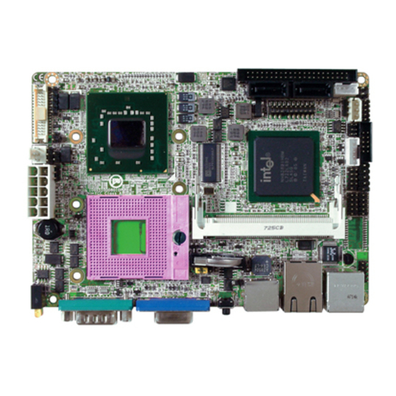
Page 7: Jumpers & Connectors Location
Jumpers & Connectors Location IDE1 CON1 SATA1 SATA2 LPT1 9 10 ATX1 MINIPCI1 23 24 JBAT1 USB3 KBM1 LAN2 RES1 COM2 VGA1 200pin DDR II SO-DIMM Socket CFD1 - 7 -... - Page 8 Jumpers Connectors IDE1: Primary IDE Connector (1) JP1, JP3: COM Port Power Special Support Connector type: 2.00mm pitch 2x22-pin box headers (8),(21) Connector type: 2.54mm pitch 1x3-pin headers Mode Standard signal for Pin-9 Description Description (Default) IDE RESET +12V DATA7 DATA8 DATA6 DATA9...
- Page 9 IR1: Infrared Connector (3) DIO1: Digital I/O Connector (10) Connector type: 2.54mm pitch 1x5-pin headers DIO1 is a 8-bit DIO connector w/ Onboard 10-pin header connector, supports 4-bit In/ 4-bit Out. Description Connector type: 2.00 mm pitch 2x5-pin headers Description Pin Description DIO1 DIO2...
- Page 10 COM1: RS-232 Connector (13) ATX1: ATX Power Supply Connector (22) Connector type: 2.00mm pitch 2x5-pin headers Description Pin Description Pin Desc. Desc. 5VSB PS-ON DCD# DTR# DSR# -12V +12V RTS# CTS# +3.3V CPUF1: Fan Power Connector (15) LAN1: GbE Connector (24) CPUF1 is a 3-pin headers for the CPU fan.
- Page 11 VGA1: Analog RGB Connector (29) CFD1 : Compact Flash Disk socket (share with Connector type: D-Sub 15-pin female connector IDE1) (34) Desc. Desc. GREEN BLUE D-DATA H-SYNC V-SYNC D-DCLK Description Description RES1 : Reset Switch (30) CF_Detect PDD3 PDD11 KBM1: Keyboard & Mouse (31) PDD4 PDD12 Mini-Din Keyboard &...
- Page 12 This page is intentionally left blank. - 12 -...
Need help?
Do you have a question about the EmCORE-i9651 and is the answer not in the manual?
Questions and answers