Table of Contents
Advertisement
Quick Links
Download this manual
See also:
User Manual
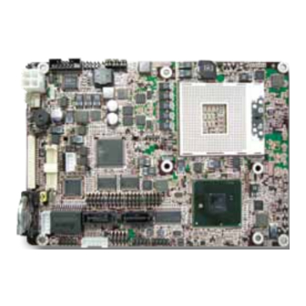
Form Factor
3.5" Compact Board
Video
Dual Channels 24-bit
LVDS/ Analog RGB/
DisplayPort
I/O
CFast/ SATA/ USB/ COM
♦ Technical Support
If you have any technical difficulties, please consult the user's manual first at:
ftp://ftp.arbor.com.tw/pub/manual
Please do not hesitate to call or e-mail our customer service when you still can not
find out the answer.
http://www.arbor.com.tw
E-mail: info@arbor.com.tw
Declaration of Conformity
FCC Class A
This device complies with Part 15 of the FCC Rules. Operation is subject to the
following two conditions : (1) this device may not cause harmful interference, and
(2) this device must accept any interference received, including interference that
may cause undesired operation.
Copyright
2011 All Rights Reserved.
®
EmCORE-i55M0
CPU
Socket-G rPGA988A
supports Intel
i5-520M/ Celeron P4500
Processor
LAN
Intel
Gigabit Ethernet
®
i7-620M/
®
82583V PCIe
- 1 -
3.5" Compact Board
Quick Installation Guide
Chipset
®
Intel
HM55
Audio
Realtek ALC662 HD Audio
CODEC, Line-in/ Line-out/
Mic-in
4041055000120P
Version 1.2
Advertisement
Table of Contents

Related Manuals for Arbor Technology EmCORE-i55M0


Summary of Contents for Arbor Technology EmCORE-i55M0
-
Page 1: Quick Installation Guide
EmCORE-i55M0 3.5" Compact Board Quick Installation Guide Version 1.2 Form Factor Chipset 3.5" Compact Board Socket-G rPGA988A ® Intel HM55 ® supports Intel i7-620M/ i5-520M/ Celeron P4500 Processor Video Audio Dual Channels 24-bit Realtek ALC662 HD Audio ® Intel 82583V PCIe... -
Page 2: Packing List
Packing List Before you begin installing your Compact Board, please make sure that the following materials have been shipped: 1 x EmCORE-i55M0 3.5" Compact Board with heatsink 1 x Driver CD 1 x Quick Installation Guide If any of the above items is damaged or missing, contact your vendor immediately. -
Page 3: The Installation Paths Of Cd Driver
The Installation Paths of CD Driver Windows XP Driver Path Management Engine CHIPSET \CHIPSET\INTEL\INF 9.11 NET Framework \NET Framework \GRAPHICS\WINXP_32_14425 \GRAPHICS\WINXP_64_14425 \ETHERNET\INTEL\82583V\32 \ETHERNET\INTEL\82583V\64 AUDIO \AUDIO\REALTEK_HD\XP_WDM_R255 Windows 7 Driver Path Management Engine CHIPSET \CHIPSET\INTEL\INF 9.11 \GRAPHICS\Win7_32_15179 \GRAPHICS\Win7_64_15179 \ETHERNET\INTEL\82583V\32 \ETHERNET\INTEL\82583V\64 AUDIO \AUDIO\REALTEK_HD\Win7_R255 Note: Before install the Management Engine driver, please copy the MEI_ALLOS_6.1.0.1042_PV.exe into a writable storage device and then... -
Page 4: Specifications
Specifications Form Factor 3.5" Compact Board Socket-G rPGA988A supports Intel i7-620M at 2.66GHz/ ® i5-520M at 2.40GHz/ Celeron P4500 at 1.86GHz Processor Chipset Intel PCH HM55 ® 1 x 204-pin SO-DIMM socket supporting up to 4GB DDR3 System Memory 1066/800MHz SDRAM (Bottom side) Integrated Intel HD Graphics Controller fifth generation ®... -
Page 5: Board Dimensions
Board Dimensions 101.96 3.38 95.20 29.40 9.25 36.09 Unit: mm - 5 -... - Page 6 29.40 9.25 36.09 - 6 -...
- Page 7 Jumpers/ Connectors Quick Reference Jumpers Label Function JPWR1 AT/ATX Power Mode Selection JBAT1 Clear CMOS Setting JRS1 COM2 RS-232 / 422 / 485 Selection JVLCD1 LCD Voltage Selection COM1 pin-1 signal setting Connectors Label Function INV1 LCD Inverter Connector LVDS1 LVDS LCD Connector DisplayPort Connector LPC1...
- Page 8 Jumpers Location JBAT1 JVLCD1 JPWR1 JRS1 rPGA-989 Intel PCH HM55 - 8 -...
-
Page 9: Connectors Location
Connectors Location INV1 LVDS1 LPC1 CPUF1 12VIN1 SMBUS1 BAT2 AUDIO1 LAN1 JCON1 JFRT1 KBMS1 CRT1 USB2 CFAST1 USB1 SATA1 SATA2 rPGA-989 Intel PCH COM1 HM55 COM2 COM3 COM4 DIMM1 - 9 -... - Page 10 Connectors Jumpers JBAT1: Clear CMOS Setting (1) INV1: LCD Inverter Connector (6) Connector type: 2.00mm pitch 1x5-pin box wafer Connector type: 2.54mm pitch 1x3-pin headers. connector. Mode Description Keep CMOS (Default) +12V Clear CMOS Backlight on/off Brightness control JV1: COM1 Pin-1 Signal Selection (2) The voltage of pin-1 could be selected by JV1 in +5V LVDS1: LVDS LCD Connector (7) or DCD.
- Page 11 LPC1: Low Pin Count Connector (9) CFAST1: CFAST Socket (14, bottom side) Connector type: CVILUX 0.5mm CF20141U0*0-LF Desc. connector SGND1 Pin Desc. Pin Desc. LPC_D0 LPC_RST# LPC_D1 SGND2 LPC_D2 LPC_CLK_33Mhz LPC_D3 LPC_FRAME#13 +3.3V SGND SERIRQ +3.3V CPUF1: Fan Power Connector (10) CPUF1 is a 3-pin headers for the CPU fan.
- Page 12 SATA1~2: Serial ATA Connectors (20, 21) JCON1: RS-422/485 Output Connector (26) High speed transfer rates (300MB/s). Connector type: 2.00mm pitch 1x4-pin box wafer connector. Pin Desc. Pin RS-422 RS-485 DATA+ DATA- LAN1: GbE Connector (27) Connector type: 2.00mm pitch 2x5-pin headers. USB1~2: USB Connectors (22, 23) Pin Desc.
Need help?
Do you have a question about the EmCORE-i55M0 and is the answer not in the manual?
Questions and answers