Arbor Technology EmCORE-i55M0 User Manual
3.5" compact board
Hide thumbs
Also See for EmCORE-i55M0:
- Quick installation manual (13 pages) ,
- Quick installation manual (12 pages)
Table of Contents
Advertisement
Quick Links
Advertisement
Table of Contents

Related Manuals for Arbor Technology EmCORE-i55M0


Summary of Contents for Arbor Technology EmCORE-i55M0
- Page 1 EmCORE-i55M0 3.5" Compact Board User’s Manual Version 1.0 2011.06...
- Page 2 This page is intentionally left blank.
-
Page 3: Table Of Contents
Index Contents Chapter 1 - Introduction ..............1 1.1 Copyright Notice ..............2 1.2 Declaration of Conformity ..........2 1.3 About this User’s Manual ...........3 1.4 Warning ................3 1.5 Replacing the Lithium Battery ...........3 1.6 Technical Support ...............3 1.7 Warranty ................4 1.8 Packing List .................5 1.9 Ordering Information ............5 1.10 Specifications ..............6 1.11 Board Dimensions.............7... - Page 4 Index CRT1: Analog RGB Connector ........34 KBMS1: Keyboard & Mouse Connector ......35 CON1: RS-422/485 Output Connector ......36 LAN1: GbE Connector ...........37 BAT2: External Battery connector .......38 SMBUS1: External SMBus Connector ......39 2.4 The Installation Paths of CD Driver .........40 Chapter 3 - BIOS ................41 3.1 BIOS Introduction .............42 3.2 Advanced Settings ............44 3.2.1 ACPI Settings ............45...
- Page 5 Index Appendix ..................79 Appendix-A I/O Port Address Map .........80 Appendix-B Interrupt Request Lines (IRQ) ......82 Appendix-C BIOS memory mapping ........83 Appendix-D Watchdog Timer (WDT) Setting ......84 - iii -...
- Page 6 This page is intentionally left blank. - iv -...
-
Page 7: Chapter 1 Introduction
Introduction Chapter 1 Introduction Chapter 1 - Introduction - 1 -... -
Page 8: Copyright Notice
RoHS ARBOR Technology Corp. certifies that all components in its products are in compliance and conform to the European Union’s Restriction of Use of Hazardous Substances in Electrical and Electronic Equipment (RoHS) Directive 2002/95/EC. -
Page 9: About This User's Manual
Introduction ARBOR Technology Corp. hereby states that the listed products do not contain unintentional additions of lead, mercury, hex chrome, PBB or PBDB that exceed a maximum concentration value of 0.1% by weight or for cadmium exceed 0.01% by weight, per homogenous material. Homogenous material is defined as a substance or mixture of substances with uniform composition (such as solders, resins, plating, etc.). -
Page 10: Warranty
Introduction 1.7 Warranty This product is warranted to be in good working order for a period of two years from the date of purchase. Should this product fail to be in good working order at any time during this period, we will, at our option, replace or repair it at no additional charge except as set forth in the following terms. -
Page 11: Packing List
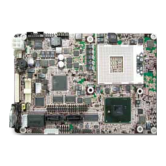
Packing List Before you begin installing your single board, please make sure that the following materials have been shipped: 1 x EmCORE-i55M0 3.5" Compact Board with heat sink 1 x Driver CD 1 x Quick Installation Guide If any of the above items is damaged or missing, contact your vendor immediately. -
Page 12: Specifications
Introduction 1.10 Specifications Form Factor 3.5” Compact Board Socket-G rPGA988A supports Intel i7-620M at 2.66GHz/ ® i5-520M at 2.40GHz/ Celeron P4500 at 1.86GHz Processor Chipset Intel PCH HM55 ® 1 x 204-pin SO-DIMM socket supporting up to 4GB DDR3 System Memory 1066/800MHz SDRAM (Bottom side) Integrated Intel HD Graphics Controller fifth generation... -
Page 13: Board Dimensions
Introduction 1.11 Board Dimensions Top View 101.96 3.38 95.20 29.40 9.25 36.09 Unit: mm - 7 -... -
Page 14: Bottom View
Introduction Bottom View 29.40 9.25 36.09 - 8 -... -
Page 15: Installing The Cpu
Introduction 1.12 Installing the CPU The processor socket comes with a screw to secure the CPU. As showing in the picture as bellow, loose the screw first before inserting the CPU. Place the CPU into the socket by making sure the notch on the corner of the CPU corresponding with the notch on the inside of the socket. -
Page 16: Installing The Memory
Introduction 1.13 Installing the Memory Side notch Latch knob Latch claw Latch section Latch arm Polarizing key To install the Memory module, locate the Memory SO-DIMM slot on the board and perform as below: Adjust the socket polarizing key and the board key to the same direction. Insert the board obliquely. -
Page 17: Chapter 2 Installation
Installation Chapter 2 Installation Chapter 2 - Installation - 11 -... -
Page 18: Block Diagram
Installation 2.1 Block Diagram EmCORE-i55M0 Intel® Dual Core i7-620M/ ATX Aux. PWR Dual Channel DDR3 1 x 204-pin DDR3 i5-520M/ (AT/ATX mode) SO-DIMM socket 800/1066 MT/z Celeron P4500 Processor DMI2 (x4) 4 x USB 2.0 ports (USB0 ~ USB3) Dual Channels 24-bit LVDS... -
Page 19: Jumpers
Installation 2.2 Jumpers JBAT1 JVLCD1 JPWR1 JRS1 rPGA-989 Intel PCH HM55 - 13 -... -
Page 20: Jbat1: Clear Cmos Setting
Installation JBAT1: Clear CMOS Setting (1) If the board refuses to boot due to inappropriate CMOS settings here is how to proceed to clear (reset) the CMOS to its default values. Connector type: 2.54mm pitch 1x3-pin headers Mode Keep CMOS (Default) Clear CMOS You may need to clear the CMOS if your system cannot boot up because you forgot your password, the CPU clock setup is incorrect, or the CMOS settings... - Page 21 Installation PC17 JBAT1 - 15 -...
-
Page 22: Jv1: Com1 Pin-1 Signal Setting
Installation JV1: COM1 pin-1 signal setting (2) The voltage of pin-1 could be selected by JV1 in +5V or DCD. Connector type: 2.54 mm pitch 1x3-pin headers Voltage DCD (Default) PC17 - 16 -... -
Page 23: Jvlcd1: Lcd Panel Voltage Selection
Installation JVLCD1: LCD Panel Voltage Selection (3) The voltage of LCD panel could be selected by JVLCD1 in +5V or +3.3V. Connector type: 2.54 mm pitch 1x3-pin headers Voltage +3.3V (Default) JVLCD1 PC17 - 17 -... -
Page 24: Jpwr1: At/Atx Power Mode Selection
Installation JPWR1: AT/ATX Power Mode Selection (4) The power mode jumper selects the power mode for the system. Connector type: 2.00mm pitch 1x3-pin headers. Mode Short AT Mode Open ATX Mode (Default) JPWR1 PC17 Note: To activate the ATX power mode, you must turn on the power button switch first (the connector for power button switch is located in JFRT1). -
Page 25: Jrs1: Com2 Rs-232/422/485 Mode Selection
Installation JRS1: COM2 RS-232/422/485 Mode Selection (5) The onboard COM2 port can be configured to operate in RS-422 or RS-485 modes. RS-422 modes differ in the way RX/TX is being handled. Jumper JRS1 switches between RS-232 or RS-422/485 mode. All RS-232/422/482 modes are available on COM2. -
Page 26: Connectors
Installation 2.3 Connectors INV1 LVDS1 LPC1 CPUF1 12VIN1 SMBUS1 BAT2 AUDIO1 LAN1 CON1 JFRT1 KBMS1 CRT1 USB2 CFAST1 USB1 SATA1 SATA2 rPGA-989 Intel PCH COM1 HM55 COM3 COM2 COM4 DIMM1 - 20 -... -
Page 27: Inv1: Lcd Inverter Connector
Installation INV1: LCD Inverter Connector (6) Connector type: 2.00mm pitch 1x5-pin box wafer connector. Pin Description INV_VCC12 Backlight on Brightness control PC17 INV1 - 21 -... -
Page 28: Lvds1: Lvds Lcd Connector
Installation LVDS1: LVDS LCD Connector (7) Connector type: ACES 1.25mm 87209-304*-06 connector and supports 24- bit dual channels. Pin Desc. Pin Desc. TX2CLK+ TX1CLK+ TX2CLK- TX1CLK- 10 TX2D0+ TX1D0+ 12 TX2D0- TX1D0- 14 GND 16 TX2D1+ TX1D1+ 18 TX2D1- TX1D1- 20 GND 22 TX2D2+ TX1D2+... -
Page 29: Dp1: Displayport Connector
Installation DP1: DisplayPort Connector (8) Connector type: ACES 1.25mm 87209-304*-06 connector. Pin Desc. Pin Desc. LANE_0P LANE_3N LANE_0N CONF1 LANE_1P CONF2 LANE_1N AUXP AUXN LANE_2P LANE_2N RTN_PWR 10 LANE_3P PWR(3.3V) PC17 - 23 -... -
Page 30: Lpc1: Low Pin Count Connector
Installation LPC1: Low Pin Count Connector (9) Connector type: CVILUX 0.5mm CF20141U0*0-LF connector. Pin Desc. Pin Desc. LPC_D0 LPC_RST# LPC_D1 LPC_ LPC_D2 CLK_33Mhz LPC_D3 LPC_FRAME# +3.3V SERIRQ +3.3V LPC1 PC17 - 24 -... -
Page 31: Cpuf1: Fan Power Connector
Installation CPUF1: Fan Power Connector (10) CPUF1 is a 3-pin headers for the CPU fan. The fan must be a +12V fan. Pin Description +12V FAN_Detect CPUF1 PC17 - 25 -... -
Page 32: 12Vin1: Atx +12V Connector
Installation 12VIN1: ATX +12V Connector (11) PWR1 supplies ATX +12V (Vcore). Pin Description Pin Description +12V +12V 12VIN1 PC17 - 26 -... -
Page 33: Audio1: Audio Connector
Installation AUDIO1: Audio Connector (12) Connector type: 2.00mm pitch 2x5-pin box headers. Pin Description Pin Description Line Left In Line Right In MIC_L MIC_R 9 10 Line-out Left 10 Line-out Right AUDIO1 PC17 - 27 -... -
Page 34: Jfrt1: Switches And Indicators
Installation JFRT1: Switches and Indicators (13) It provides connectors for system indicators that provides light indication of the computer activities and switches to change the computer status. Connector type: 2.00mm pitch 2x5-pin headers. Pin Description Pin Description RESET+ RESET- POWER_LED+ POWER_LED- HDD_LED+ HDD_LED-... -
Page 35: Cfast1: Cfast Socket
Installation CFAST1: CFAST Socket (14, bottom side) Desc. SGND1 SGND2 SGND LED1 LED2 PC10 PC11 PC12 PC13 3.3V PC14 3.3V PC15 PC16 PC17 CFAST1 PC17 - 29 -... -
Page 36: Dimm1: So-Dimm Socket
Installation DIMM1: SO-DIMM Socket (15, bottom side) PC17 DIMM1 - 30 -... -
Page 37: Com1~4: Serial Port Connectors
Installation COM1~4: Serial Port Connectors (16, 17, 18, 19) Connector type: 2.00mm pitch 2x5-pin headers. Pin Description Pin Description DCD# DTR# DSR# RTS# CTS# 10 N/C PC17 COM1 COM2 COM3 COM4 - 31 -... -
Page 38: Sata1~2: Serial Ata Connectors
Installation SATA1~2: Serial ATA Connectors (20, 21) High speed transfer rates (300MB/s). Pin Description PC17 SATA1 SATA2 - 32 -... -
Page 39: Usb1~2: Usb Connectors
Installation USB1~2: USB Connectors (22, 23) Connector type: 2.00mm pitch 2x5-pin headers. Pin Description Pin Description USBD- USBD- USBD+ USBD+ 10 N/C (Key) PC17 USB2 USB1 - 33 -... -
Page 40: Crt1: Analog Rgb Connector
Installation CRT1: Analog RGB Connector (24) Connector type: 2.00mm pitch 2x5-pin headers. Pin Description Pin Description GREEN BLUE H_SYNC V_SYNC 10 CRT_DET PC17 CRT1 - 34 -... -
Page 41: Kbms1: Keyboard & Mouse Connector
Installation KBMS1: Keyboard & Mouse Connector (25) Connector type: 2.0mm pitch 1x6-pin box wafer connector. Pin Description KB_DAT MS_DAT KB_CLK MS_CLK PC17 KBMS1 - 35 -... -
Page 42: Con1: Rs-422/485 Output Connector
Installation CON1: RS-422/485 Output Connector (26) Connector type: 2.00mm pitch 1x4-pin box wafer connector. Pin RS-422 Pin RS-485 DATA+ DATA- PC17 CON1 - 36 -... -
Page 43: Lan1: Gbe Connector
Installation LAN1: GbE Connector (27) Connector type: 2.00mm pitch 2x5-pin headers. Pin Description Pin Description TX+/ MDI0+ TX/ MDI0- RX+/ MDI1+ N/C/ MDI2+ N/C/ MDI2- RX-/ MDI1- N/C/ MDI3+ N/C/ MDI3- N/C (Key) PC17 LAN1 - 37 -... -
Page 44: Bat2: External Battery Connector
Installation BAT2: External Battery connector (28, Optional) Connector type: 1.25mm pitch 1x2-pin wafer connector. Pin Description 3.3 V battery PC17 BAT2 - 38 -... -
Page 45: Smbus1: External Smbus Connector
Installation SMBUS1: External SMBus Connector (29) Connector type: 2.5mm pitch 1x3-pin box wafer connector. Pin Description Data Clock PC17 SMBUS1 - 39 -... -
Page 46: The Installation Paths Of Cd Driver
BIOS 2.4 The Installation Paths of CD Driver Windows XP Driver Path Management En- gine CHIPSET \CHIPSET\INTEL\INF 9.11 NET Framework \NET Framework \GRAPHICS\WINXP_32_14425 \GRAPHICS\WINXP_64_14425 \ETHERNET\INTEL\82583V\32 \ETHERNET\INTEL\82583V\64 AUDIO \AUDIO\REALTEK_HD\XP_WDM_R255 Windows 7 Driver Path Management En- gine CHIPSET \CHIPSET\INTEL\INF 9.11 \GRAPHICS\Win7_32_15179 \GRAPHICS\Win7_64_15179 \ETHERNET\INTEL\82583V\32 \ETHERNET\INTEL\82583V\64 AUDIO... -
Page 47: Chapter 3 - Bios
BIOS Chapter 3 BIOS Chapter 3 - BIOS - 41 -... -
Page 48: Bios Introduction
BIOS 3.1 BIOS Introduction The AMI BIOS provides a Setup utility program for specifying the system configurations and settings. The BIOS ROM of the system stores the Setup utility and configurations. When you turn on the computer, the AMI BIOS is immediately activated. To enter the BIOS SETUP UTILILTY, press “Delete”... -
Page 49: System Date
BIOS Key Commands BIOS Setup Utility is mainly a key-based navigation interface. Please refer to the following key command instructions for navigation process. Move to highlight a particular configuration screen from “←”“→” the top menu bar / Move to highlight items on the screen “↓”... -
Page 50: Advanced Settings
BIOS 3.2 Advanced Settings The “Advanced” screen provides setting options to configure ACPI, CPU, SATA, USB, Super IO and other peripherals. You can use “←” and “→” keys to select “Advanced” and use the “↓” and “↑” to select a setup item. Note: please pay attention to the instructions at the upper-right frame before you decide to configure any setting of an item. -
Page 51: Acpi Settings
BIOS 3.2.1 ACPI Settings Press “Enter” on “ACPI Settings” and you will be able to set up ACPI configu- ration. Enable ACPI Auto Configuration Allow you to enable or disable BIOS ACPI Auto Configuration. Enable Hibernation Allow you to enable or disable system hibernation (OS/S4 Sleep State). This option may not be effective in some OSes. -
Page 52: Cpu Configuration
BIOS 3.2.2 CPU Configuration Press “Enter” on “CPU Configuration” to configure the CPU on the “CPU Con- figuration” screen. CPU Details Detail information including CPU manufacturer name, Processor Speed, Pro- cessor Stepping, Microcode Revision, Processor Core number, etc. Hyper-Threading Technology Enabled: activates the Hyper-Threading Technology for higher CPU threading speed. -
Page 53: Active Processor Cores
BIOS Active Processor Cores Number of cores to enable in each processor package. The choice: All, 1, 2 Limit CPUID Maximum Disable for Windows XP. The choice: Disabled, Enabled Hardware Prefetcher To turn on/off the MLC streamer prefetcher. The choice: Disabled, Enabled Adjacent Cache Line Prefetch To turn on/off prefetching of adjacent cache lines. -
Page 54: Sata Configuration
BIOS 3.2.3 SATA Configuration It allows you to select the operation mode for SATA controller. Serial-ATA Controller 0 Enable/ Disable Serial ATA Controller 0. The choice: Disable, Enhanced, Compatible Serial-ATA Controller 1 Enable/ Disable Serial ATA Controller 0. The choice: Disable, Enhanced - 48 -... -
Page 55: Intel Igd Swsci Opregion
BIOS 3.2.4 Intel IGD SWSCI OpRegion DVMT/ Fixed Memory This feature allows you to select the memory size of DVMT/BOTH operating mode. The choice: 256MB, 128MB, Maximum IGD – Boot Type This feature allows you to select the display device when you boot up the system. -
Page 56: Usb Configuration
BIOS LCD Panel Type This feature allows you to select displayed Panel Resolution in accordance with LCD Panel. The choice: VBIOS Default, 640x480 18/1, 800x600 18/1, 1024x768 18/1, 1280x1024 24/2, 1024x600 18/2, 1400x900 24/2, 1600x1200 18/2, 1280x768 18/1, 1680x1050 24/2, 1920x1080 24/2, 1024x768 24/1, 1366x768 24/1, 800x400 18/1, 1280x800 18/1, 1280x720 24/1, 2048x1536 24/2 Spread Spectrum Clock Chip Allow you to select Off, Hardware or Software. -
Page 57: Legacy Usb Support
BIOS Legacy USB Support Enable support for legacy USB. Normally if this option is not enabled, any attached USB mouse or USB keyboard won’t be accessible until a USB com- patible operating system is fully booted with all loaded USB drivers. When this option is enabled, any attached USB mouse or USB keyboard can control the system even when there is no USB driver loaded onto the system. -
Page 58: Super Io Configuration
BIOS 3.2.6 Super IO Configuration You can use this item to set up or change the Super IO configuration for FDD controllers, parallel ports and serial ports. - 52 -... -
Page 59: H/W Monitor
BIOS 3.2.7 H/W Monitor The H/W Monitor lists out the temperature and voltage information that is be- ing monitored. System/ CPU Temperature Show you the current System / CPU fan temperature. CPU Fan Speed Show you the current CPU Fan operating speed. Vcore Show you the voltage level of CPU (Vcore). -
Page 60: Second Super Io Configuration
BIOS 3.2.8 Second Super IO Configuration You can use this item to set up or change the Second Super IO configuration for FDD controllers, parallel ports and serial ports. - 54 -... -
Page 61: Serial Port
BIOS Serial Port 1~4 Configuration Serial Port Use the Serial port option to enable or disable the serial port. The choice: Enabled, Disabled Change Settings Use the Change Settings option to change the serial port’s IO port address and interrupt address. The choice: IO=3F8h;... -
Page 62: Thermal Configuration
BIOS 3.2.9 Thermal Configuration - 56 -... - Page 63 BIOS Select “Platform Thermal Configuration” or “Intelligent Power Sharing“ to access the submenus showing below. - 57 -...
- Page 64 BIOS ME SMBus Thermal Reporting Enable/Disable ME SMBus Thermal Reporting Configuration. PCH Thermal Device Enable/Disable MCH Temp Read, PCH Temp Read, CPU Energy Read, CPU Temp Read, Alert Enable Lock functions. - 58 -...
-
Page 65: Advanced Chipset Settings
BIOS 3.3 Advanced Chipset Settings Select “Chipset” to enable CRID, access “North Bridge”, “South Bridge” and “ME Subsystem”. - 59 -... -
Page 66: North Bridge
BIOS 3.3.1 North Bridge Low MMIO Align This option aligns Low MMIO resources together. The choice: Enabled, Disabled Initate Graphic Adapter This item allows you to select which graphics controller to use and set it as the primary boot device. The choice: IGD, PCI/IGD, PCI/PEG, PEG/IGD, PEG/PCI - 60 -... -
Page 67: South Bridge
BIOS 3.3.2 South Bridge Normally, the south bridge controls the basic I/O functions, such as USB and audio. This screen allows you to access the configurations of I/Os. SMBus Controller SMBus Controller help The choice: Enabled, Disabled GbE Controller GbE Controller help The choice: Enabled, Disabled Wake on Lan from S5 Wake on Lan from S5 help... - Page 68 BIOS Azalia HD Audio Use the Azalia HD Audio option to enable or disable the High Definition Audio controller. The choice: Enabled, Disabled USB Configuration Select “USB Configuration“ to enter the following screen. The USB Configuration menu is used to read USB configuration information and configure the USB settings.
-
Page 69: Me Subsystem
BIOS 3.3.3 ME Subsystem Use the ME Subsystem menu to configure the Intel® Management Engine (ME) configuration options. ME Subsystem Use the ME Subsystem option to enable or disable the Intel® ME subsystem. The choice: Enabled, Disabled End of Post Message Use the End of Post Message option to enable or disable the end of post mes- sage of the ME Subsystem. -
Page 70: Boot Settings
BIOS 3.4 Boot Settings Quiet Boot This item can helps to select screen display when the system boots. The choice: Enabled, Disabled Fast Boot Enable/Disable boot with initialization of a minimal set of devices required to launch active boot option. Ineffective for BBS boot options. The choice: Enabled, Disabled Setup Prompt Timeout Seconds to wait for setup activation key. -
Page 71: Security
BIOS 3.5 Security You can set administrator password by Security menu. - 65 -... -
Page 72: Exit Options
BIOS 3.6 Exit Options Use the option to exit BIOS settings, and save/discard any changes you made. - 66 -... -
Page 73: Beep Sound Codes List
BIOS 3.7 Beep Sound codes list 3.7.1 Boot Block Beep codes Number of Beeps Description Insert diskette in floppy drive A: ‘AMIBOOT.ROM’ file not found in root directory of diskette in A: Flash Programming successful Floppy read error Keyboard controller BAT command failed No Flash EPROM detected Floppy controller failure Boot Block BIOS checksum error... -
Page 74: Troubleshooting Post Bios Beep Codes
BIOS 3.7.3 Troubleshooting POST BIOS Beep codes Number of Beeps Description Reseat the memory, or replace known good 1, 2 or 3 modules. Fatal error indicating a serious problem with the system. Consult your system manufacturer. Before declaring the motherboard beyond all hope, eliminate the possibility of interference by a malfunctioning add-in card. -
Page 75: Ami Bios Checkpoints
BIOS 3.8 AMI BIOS Checkpoints 3.8.1 Bootblock Initialization Code Checkpoints The Bootblock initialization code sets up the chipset, memory and other components before system memory is available. The following table describes the type of checkpoints that may occur during the bootblock initialization portion of the BIOS (Note) Checkpoint... - Page 76 BIOS Both key sequence and OEM specific method is checked to determine if BIOS recovery is forced. If BIOS recovery is necessary, control flows to checkpoint E0. See Bootblock Recovery Code Checkpoints section of document for more information. Restore CPUID value back into register. The Bootblock- Runtime interface module is moved to system memory and given control to it.
-
Page 77: Bootblock Recovery Code Checkpoints
BIOS 3.8.2 Bootblock Recovery Code Checkpoints The Bootblock recovery code gets control when the BIOS determines that a BIOS recovery needs to occur because the user has forced the update or the BIOS checksum is corrupt. The following table describes the type of checkpoints that may occur during the Bootblock recovery portion of the BIOS (Note) Checkpoint... - Page 78 BIOS Erase the flash part. Program the flash part. The flash has been updated successfully. Set flash write disabled. Disable ATAPI hardware. Restore CPUID value back into register. Give control to F000 ROM at F000:FFF0h. - 72 -...
-
Page 79: Post Code Checkpoints
BIOS 3.8.3 POST Code Checkpoints The POST code checkpoints are the largest set of checkpoints during the BIOS pre-boot process. The following table describes the type of checkpoints that may occur during the POST portion of the BIOS (Note) Checkpoint Description Disable NMI, Parity, video for EGA, and DMA controllers. - Page 80 BIOS Early CPU Init Exit Initialize the 8042 compatible Key Board Controller. Detect the presence of PS/2 mouse. Detect the presence of Keyboard in KBC port. Test and initialize different input devices. Also, update the Kernel Variables. Trap the INT09h vector, so that the POST INT09h handler gets control over IRQ1.
- Page 81 BIOS Initialize DMAC-1 & DMAC-2. Initialize RTC date/time. Test for total memory installed in the system. Also, check for DEL keys to limit memory test. Display total memory in the system. Mid POST initialization of chipset registers. Detect different devices (Parallel ports, serial ports, and coprocessor in CPU, …...
- Page 82 BIOS Initialize runtime language module. Display boot option’s popup menu. Display the system configuration screen if enabled. Initialize the CPU’s before boot, which includes the programming of the MTRR’s. Wait for user input at config display if needed. Uninstall POST INT1Ch vector and INT09h vector. Prepare BBS for Int 19 boot.
-
Page 83: Dim Code Checkpoints
BIOS 3.8.4 DIM Code Checkpoints The Device Initialization Manager (DIM) gets control at various times during BIOS POST tries to initialize different system buses. The following table describes the main checkpoints where the DIM module is accessed (Note) Checkpoint Description Initialize different buses and perform the following functions: Reset, Detect, and Disable (function 0);... -
Page 84: Acpi Runtime Checkpoints
BIOS 3 = func#3, input device initialization on the BUS concerned. 4 = func#4, IPL device initialization on the BUS concerned. 5 = func#5, general device initialization on the BUS concerned. 6 = func#6, error reporting for the BUS concerned. 7 = func#7, add-on ROM initialization for all BUSes. -
Page 85: Appendix
Appendix Appendix Appendix - 79 -... -
Page 86: Appendix-A I/O Port Address Map
Appendix Appendix-A I/O Port Address Map Each peripheral device in the system is assigned a set of I/O port addresses, which is the identity for the device. The following table lists the I/O port addresses used. Address Device Description 00000000 - 0000000F DMA Controller 00000000 - 00000CF7 PIC bus... - Page 87 Appendix 000000C0 - 000000DF DMA Controller 000000E0 - 000000EF Motherboard Resource 000000F0 - 000000FF Math Co-processor 00000170 - 00000177 Secondary IDE Channel 000001F0 - 000001F7 Primary IDE Channel 00000274 - 00000277 ISAPNP Read Data Port 00000279 - 00000279 ISAPNP Read Data Port 00000290 - 0000029F Motherboard Resource 000002E8 - 000002EF...
-
Page 88: Appendix-B Interrupt Request Lines (Irq)
Appendix 0000F040 - 0000F043 Intel(R) 5 Series/3400 Series Chipset Family 2 port Serial ATA Storage Controller 0000F050 - 0000F057 Intel(R) 5 Series/3400 Series Chipset Family 2 port Serial ATA Storage Controller 0000F060 - 0000F063 Intel(R) 5 Series/3400 Series Chipset Family 2 port Serial ATA Storage Controller 0000F070 - 0000F077 Intel(R) 5 Series/3400 Series Chipset Family 2... -
Page 89: Appendix-C Bios Memory Mapping
Appendix Appendix-C BIOS memory mapping Address Device Description 000A0000 - 000BFFFF Intel(R) HD Graphics 000A0000 - 000BFFFF PCI bus D0000000 - DFFFFFFF Intel(R) HD Graphics E0000000 - EFFFFFFF System Board FE000000 - FE3FFFFF Intel(R) HD Graphics FE400000 - FE4FFFFF Intel(R) 82583V Gigabit Network Con- nection FE400000 - FE5FFFFF Intel(R) 5 Series/3400 Series Chipset... -
Page 90: Appendix-D Watchdog Timer (Wdt) Setting
Appendix Appendix-D Watchdog Timer (WDT) Setting WDT is widely used for industry application to monitor the activity of CPU. Application software depends on its own requirement to trigger WDT with adequate timer setting. Before WDT time-out, the functional normal system will reload the WDT. - Page 91 Appendix mov AX, 2Eh mov DX, AX mov AL, 0F0h out DX, AL ; select CRF0 mov AL, 00h inc DX out DX, AL ; set CRF0=00h, output mov AX, 2Eh mov DX, AX mov AL, 0F5h out DX, AL ; select CRF5, WDT Timer unit mov AL, 00h ;...
- Page 92 Appendix outportb(0x4e, 0x87); /* twice, */ outportb(0x4e, 0x07); /* point to logical device */ outportb(0x4e+1, 0x07); /* select logical device 7 */ outportb(0x4e, 0xf5); /* select offset f5h */ outportb(0x4e+1, 0x40); /* set bit5 = 1 to clear bit5 */ outportb(0x4e, 0xf0);...
Need help?
Do you have a question about the EmCORE-i55M0 and is the answer not in the manual?
Questions and answers