Table of Contents
Advertisement
Quick Links
Advertisement
Table of Contents

Related Manuals for Arbor Technology EmCORE-i230G


Summary of Contents for Arbor Technology EmCORE-i230G
- Page 1 EmCORE-i230G 3.5” Compact Board User’s Manual Version 1.1 2017.05...
- Page 2 This page is intentionally left blank. - 2 -...
-
Page 3: Revision History
Revision History Version Release Time Description April, 2015 Initial release May, 2017 Added supported SDXC information in 1.3. Specifications 2.3.3. Connectors section - i -... - Page 4 This page is intentionally left blank. - ii -...
- Page 5 Contents Table of Contents Revision History .................i Table of Contents ................iii Preface....................v Copyright Notice ..................v Declaration of Conformity ............... v CE ....................v FCC Class A ................... vi RoHS ....................vi SVHC / REACH ................vii Warning ....................vii Replacing Lithium Battery ..............vii Technical Support ..................vii Warranty....................viii Chapter 1 - Introduction ..............1...
- Page 6 Contents 3.3. Security ..................51 3.4. Power ..................... 52 3.5. Boot ..................53 3.6. Exit ....................54 Appendices ..................55 Appendix A. Watchdog Timer (WDT) Setting ........56 Appendix B. Digital I/O Setting .............. 57 Appendix C: I/O Port Address Map ............59 Appendix D: Interrupt Request Lines (IRQ) ..........
-
Page 7: Copyright Notice
Preface Preface Copyright Notice All Rights Reserved. The information in this document is subject to change without prior notice in order to improve the reliability, design and function. It does not represent a commitment on the part of the manufacturer. Under no circumstances will the manufacturer be liable for any direct, indirect, special, incidental, or consequential damages arising from the use or inability to use the product or documentation, even if advised of the possibility of such... - Page 8 (PBDE) in electrical and electronic products. Member states of the EU are to enforce by 7/1/2006. ARBOR Technology Corp. hereby states that the listed products do not contain unintentional additions of lead, mercury, hex chrome, PBB or PBDB that exceed a maximum concentration value of 0.1% by weight or for cadmium exceed...
-
Page 9: Replacing Lithium Battery
Preface SVHC / REACH To minimize the environmental impact and take more responsibility to the earth we live, Arbor hereby confirms all products comply with the restriction of SVHC (Substances of Very High Concern) in (EC) 1907/2006 (REACH --Registration, Evaluation, Authorization, and Restriction of Chemicals) regulated by the European Union. - Page 10 Preface Warranty This product is warranted to be in good working order for a period of two years from the date of purchase. Should this product fail to be in good working order at any time during this period, we will, at our option, replace or repair it at no additional charge except as set forth in the following terms.
-
Page 11: Chapter 1 - Introduction
Chapter 1 Introduction Chapter 1 - Introduction - 1 -... -
Page 12: The Product
Introduction 1.1. The Product • Support Intel® Atom™ Processor E3800 family • Integrated Gigabit Ethernet • LVDS, Analog RGB Port, HDMI port • Support Dual Independent Displays • Soldered Onboard eMMC (OEM request) • Wide Range Operating Temp.: -40 ~ 85°C 1.2. -
Page 13: Specifications
Introduction 1.3. Specifications Form Factor 3.5" Compact Board Soldered onboard Intel® Atom™ Processor E3825 1.33GHz or E3845 1.91GHz 1 x DDR3L SO-DIMM socket, supporting up to System Memory 8GB 1333/1600 MT/s SDRAM Graphics Chipset Integrated Intel® HD Graphics Analog RGB with resolution up to 2048x1536, HDMI Graphics Interface LVDS: Dual Channels 24-bit LVDS, with resolution up to 1920x1200 Ethernet... -
Page 14: Inside The Package
1.4. Inside the Package Before starting to install the single board, make sure the following items are shipped: 1 x EmCORE-i230G 3.5" Compact Board with heatsink 1 x Driver CD 1 x Quick Installation Guide If any of the aforelisted items is damaged or missing, contact your vendor immediately. -
Page 15: Chapter 2 - Getting Started
Chapter 2 Getting Started Chapter 2 - Getting Started - 5 -... -
Page 16: Board Dimensions
Getting Started 2.1. Board Dimensions 2.1.1. SKU-E3825 101.96 98.58 3.38 3.38 98.58 (32) Unit:mm - 6 -... -
Page 17: Sku-E3845
Getting Started 2.1.2. SKU-E3845 101.96 98.58 3.38 3.38 98.58 (25.5) Unit:mm - 7 -... -
Page 18: Block Diagram
Getting Started 2.2. Block Diagram 12VIN1 +12V DC-in USB2 1 x USB 3.0/2.0 port DDR3L-1333MHz (up to 8GB) 1 x DDR3L Type A conn. SO-DIMM socket VGA1 Analog RGB DB15 female USB1, 4 4 x USB 2.0 ports 2x5-pin 2.00mm USB Hub LVDS1 1 x eDP port... -
Page 19: Jumpers & Connectors
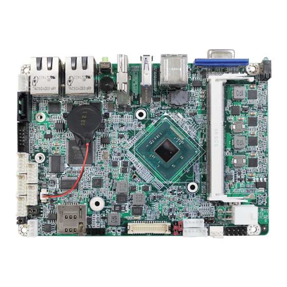
Getting Started 2.3. Jumpers & Connectors The board comes with some connectors to join some devices and also some jumpers to alter the hardware configuration. The following in this chapter will explicate each of these components one-by-one. 2.3.1. Layout This section will provide an overview of this board, both the top and bottom sides. Board Top - 9 -... - Page 20 Getting Started Board Bottom - 10 -...
-
Page 21: Jumpers
Getting Started 2.3.2. Jumpers JPIC1 Function: AT/ATX Power Mode Selection Jumper Type: 2.00mm pitch 2x3-pin header Setting: Pin Description 2-4 AT 4-6 ATX mode (default) Board Top JPIC1 - 11 -... - Page 22 Getting Started JVLCD1 Function: LCD Panel Voltage Selection Jumper Type: 2.54mm pitch 1x3-pin header Setting: Pin Description 1-2 +5V 2-3 +3.3V (default) Board Top JVLCD1 - 12 -...
- Page 23 Getting Started JINV1 Function: LCD Inverter Voltage Selection Jumper Type: 2.54mm pitch 1x3-pin header Setting: Pin Description 1-2 +12V 2-3 +5V (default) Board Top JINV1 - 13 -...
- Page 24 Getting Started JRS1 Function: COM1&2 RS-232/485 Selection Jumper Type: 2.00 mm pitch 2x3-pin header Setting: Pin Description 1-3 COM1=RS-232 (default) 3-5 COM1=RS-485 2-4 COM2=RS-232 (default) 4-6 COM2=RS-485 Note: To enable RS-485 CON1, beside jumper setting, please go to BIOS Setting Menu to Enable RS-485 mode of COM1&2. Option is under Advanced/ SIO FINTEK71869E/ RS-232/485 Setting/ RS-485.
- Page 25 Getting Started JRS2 Function: COM1&2 RS-485 Terminator Mode Selection Jumper Type: 2.00 mm pitch 2x2-pin header Setting: Status Description Set COM1 to RS-485 Open Terminator Mode (default) Set COM1 to Short RS-485 Normal Mode Set COM2 to RS-485 Open Terminator Mode (default) Set COM2 to Short RS-485 Normal Mode...
-
Page 26: Connectors
Getting Started 2.3.3. Connectors 12VIN1 Function: ATX +12V Connector Connector Type: 4-pin power connector Pin Assignment: Pin Description Pin Description 4 +12V 3 +12V 2 GND 1 GND Board Top 12VIN1 - 16 -... - Page 27 Getting Started JFRT1 Function: Provides connectors to front-panel status LED and toggles Connector Type: 2.54mm pitch 2x5-pin header Pin Assignment: Pin Description Pin Description RESET+ RESET- PLED+ PLED- HLED+ HLED- SPEAK+ SPEAK- 10 PSON- PSON+ Board Top JFRT1 - 17 -...
- Page 28 Getting Started FAN1 Function: Fan connector Connector Type: 2.54mm pitch 1x3-pin wafer connector. Pin Assignment: Description +12V Speed Board Top FAN1 - 18 -...
- Page 29 Getting Started KBMS1 Function: Keyboard & Mouse connector Connector Type: 2.0mm pitch 1x6-pin header Pin Assignment: Description KB_DATA MS_DATA KB_CLK PS2_VCC MS_CLK Board Top KBMS1 - 19 -...
- Page 30 Getting Started INV1 Function: LCD inverter connector Connector Type: 2.00mm pitch 1x5-pin box wafer Pin Assignment: Pin Description on/off Brightness control Board Top INV1 - 20 -...
- Page 31 Getting Started LVDS1 Function: LVDS LCD panel connector Connector Type: ACES 1.25mm 87209-3040-06 connector that supports 24-bit dual channels. Pin Assignment: Pin Description Pin Description 2 VDD 1 VDD 4 TX2_CLK+ 3 TX1_CLK+ 6 TX2_CLK- 5 TX1_CLK- 8 GND 7 GND 10 TX2_D0+ 9 TX1_D0+ 12 TX2_D0-...
- Page 32 Getting Started SIM1 Function: micro-SIM card socket Connector Type: REGO 80440GIH-061T-120L socket Pin Assignment: Pin Description Pin Description Board Top SIM1 - 22 -...
- Page 33 Getting Started BAT1 Function: Battery connector Connector Type: 1.25mm pitch 1x2 pin wafer connector Pin Assignment: Description Battery Power Board Top BAT1 - 23 -...
- Page 34 Getting Started CON1 Function: RS-485 connector Connector Type: 2.00mm pitch 1x4-pin wafer connector Pin Assignment: Description COM1 DATA1 + COM1 DATA1 - COM2 DATA2 + COM2 DATA2 - Note: To enable this port, please refer to JRS1 on page Board Top CON1 - 24 -...
- Page 35 Getting Started USB1,4 Function: USB 2.0 connector Connector Type: 2.00mm pitch 2x5-pin lockable box headers Pin Assignment: Pin Description Pin Description USBP1- USBP0- USBP1+ USBP0+ 10 GND Board Top USB4 USB1 - 25 -...
- Page 36 Getting Started COM1&2 Function: Serial port connector Connector Type: 2.00mm pitch 2x5-pin wafer connector Pin Assignment: Pin Description Pin Description 2 RX 1 DCD# 4 DTR# 3 TXD 6 DSR# 5 GND 8 CTS# 7 RTS# 10 N/C 9 RI# Board Top COM2 COM1...
- Page 37 Getting Started DIO1 Function: Digital I/O connector Connector Type: 2.00mm pitch 2x5-pin lockable box headers Pin Assignment: Pin Description Pin Description GPIO1 GPIO0 GPIO3 GPIO2 GPIO5 GPIO4 GPIO7 GPIO6 10 GND Board Top DIO1 - 27 -...
- Page 38 Getting Started AUDIO1 Function: Audio connector Connector Type: 2.00mm pitch 2x5-pin header Pin Assignment: Pin Description Pin Description 1 Line Left In 2 Line Right In 3 GND 4 GND 5 MIC1 6 MIC2 7 GND 8 GND 9 Line-out Left 10 Line-out Right Board Top AUDIO1...
- Page 39 Getting Started SATA1 Function: Serial ATA connector Pin Assignment: The pin assignments conform to the industry standard. Board Top SATA1 - 29 -...
- Page 40 Getting Started PWROUT1 Function: SATA power connector Connector Type: 2.00mm pitch 1x4-pin wafer connector Pin Assignment: Pin Description VCC 5V VCC 12V Board Top PWROUT1 - 30 -...
- Page 41 Getting Started LAN1, 2 Function: Ethernet connectors Connector Type: RJ-45 connector that supports 10/100/1000Mbps Ethernet Pin Assignment: Pin Description Pin Description MDI0+ MDI0- MDI1+ MDI1- MDI2+ MDI2- MDI3+ MDI3- Board Top LAN2 LAN1 - 31 -...
- Page 42 Getting Started RES1 Function: Reset button Board Top RES1 - 32 -...
- Page 43 Getting Started HDMI1 Function: HDMI connector Connector Type: 19-pin HDMI connector with flange Pin Assignment: The pin assignments conform to the industry standard. Board Top HDMI1 - 33 -...
- Page 44 Getting Started USB2 Function: USB 3.0 connector Connector Type: USB 3.0/2.0 type-A connectors Pin Assignment: The pin assignments conform to the industry standard. Board Top USB2 - 34 -...
- Page 45 Getting Started USB3 Function: Double-stacked USB connectors Connector Type: Two USB 2.0/1.0 type-A connectors Pin Assignment: The pin assignments conform to the industry standard. Board Top USB3 - 35 -...
- Page 46 Getting Started VGA1 Function: Analog RGB connector Connector Type: D-Sub 15-pin female connector Pin Assignment: Description. Pin Description GREEN BLUE D-DATA H-SYNC V-SYNC D-DCLK Board Top VGA1 - 36 -...
- Page 47 Getting Started SYSLED1: Function: Power ON & HDD LED Indicator Board Top SYSLED1 - 37 -...
- Page 48 Getting Started Function: Mini-card socket Connector Type: Onboard 0.8mm-pitch 52-pin edge card connector interconnected with SIM card socket. The pin assignments conform to the industry standard. Board Bottom - 38 -...
- Page 49 Getting Started Function: CFast card socket The pin assignments conform to the industry standard. Board Bottom - 39 -...
- Page 50 Function: Micro SDXC card socket (supports SDXC card SD 3.0 only) The pin assignments conform to the industry standard. 1 2 3 4 5 6 Board Bottom - 40 -...
-
Page 51: Driver Installation Notes
2.4. Driver Installation Notes The board supports Windows 7 and Windows 8.1. Find the necessary drivers on the CD that comes with your purchase. For different OS, the driver/utility installation may vary slightly, but generally they are similar. Find the drivers on CD by the following paths: Windows 7 Device Driver Path... - Page 52 This page is intentionally left blank. - 42 -...
-
Page 53: Chapter 3 - Bios
Chapter 3 BIOS Chapter 3 - BIOS - 43 -... - Page 54 BIOS The BIOS Setup utility is featured by BIOS to configure the system settings stored in the system’s BIOS ROM. BIOS is activated once the computer powers After entering the utility, use the left/right arrow keys to navigate between the top menus and use the down arrow key to access one.
-
Page 55: Main
BIOS 3.1. Main The Main menu displays some BIOS info and features the settings of System Date and System Time. The BIOS info displayed is: Info Item Description BIOS Version Delivers the computer’s BIOS version. Project name Delivers the name of the project Delivers the date and time when the BIOS Setup utility was created/ Build Date and Time updated. -
Page 56: Advanced
BIOS 3.2. Advanced The Advanced menu controls the system’s CPU, IDE, Super IO, AHCI and USB. It also helps users monitor hardware health. The featured submenus are: Submenu Description Boot Configuration 3.2.1. Boot Configuration on page 47. PCI Express Configuration 3.2.2. PCI Express Configuration on page 47. -
Page 57: Boot Configuration
BIOS 3.2.1. Boot Configuration Setting Description Numlock Select Power-on state for Num lock 3.2.2. PCI Express Configuration Configures PCI Express by the following settings: Setting Description PCI Express Root Port Enables/disables this PCIe port. PCIe Speed Options are: Auto, Gen 1, Gen 2 Auto is the default. PCI Express Root ASPM Support Port... -
Page 58: Video Configuration
BIOS 3.2.4. Video Configuration Configure video settings The featured setting is: Setting Description Set the hardware configuration of DDI1 Configure DDI1 as Options are LVDS (default) / No device 3.2.4.1 PTN3460 (eDP to LVDS) Configuration Setting Description Set the Output Format of PTN3460. PTN3460 Output Format Options are (00) VESA (24bpp) / (01) VESA or JEIDA (18bpp) / (10) JEIDA (24bpp) / (11) JEIDA (24bpp) Set the Channel of PTN3460. -
Page 59: Sata Configuration
BIOS 3.2.5 SATA Configuration Select this submenu to configure the SATA controller and HD. Setting Description Enables/disables the present SATA controller. SATA Controller(s) Enabled is the default. Configures how to sun the SATA drives. Configures SATA Mode Options available are AHCI (default) and IDE. SATA Port 0 Hot Plug Enables/disables hot-pluggable feature for the SATA Capability... -
Page 60: Sio Fintek71869E
BIOS 3.2.7. SIO FINTEK71869E Configures SIO by the following settings: Setting Description Set the state of Power Loss mode Power Loss mode Options are Keep last state/ Bypass mode/ Always On(default)/Always Off Serial Port A Enables/disables the Serial port. RS-232/RS-485 Setting Set the mode of Serial port. -
Page 61: Security
BIOS 3.3. Security The Security menu sets up the password for the system’s administrator account. Once the administrator password is set up, this BIOS Setup utility is limited to access and will ask for the password each time any access is attempted. The featured setting is: Setting Description... -
Page 62: Power
BIOS 3.4. Power The Power menu sets up the power option of system The featured setting is: Setting Description Enables or disables Wake on PME. Wake on PME Determines the action taken when the system power is off and a PCI Power Management Enable wake up event occurs. -
Page 63: Boot
BIOS 3.5. Boot The Boot menu configures how to boot up the system such as the configuration of boot device priority. The featured settings are: Setting Description Select the boot type. Boot Type Options are Legacy Boot Type (default), and UFEI Boot Type. Allow InsydeH20 to Skip certain tests while booting . -
Page 64: Exit
BIOS 3.6. Exit The Save & Exit menu features a handful of commands to launch actions from the BIOS Setup utility regarding saving changes, quitting the utility and recovering defaults. The features settings are: Setting Description Exit Saving Changes Saves the changes and quits the BIOS Setup utility. Save Changes Without Exit Save Changes but does not quit the BIOS. -
Page 65: Appendices
Appendices Appendices - 55 -... -
Page 66: Appendix A. Watchdog Timer (Wdt) Setting
Appendices Appendix A. Watchdog Timer (WDT) Setting The application software depends on its requirement to trigger WDT with adequate timer setting. Before WDT timeout, the functional normal system will reload the WDT. The WDT never time-out for a normal system. The WDT will not be reloaded by an abnormal system, then WDT will time-out and auto-reset the system to avoid abnormal operation. -
Page 67: Appendix B. Digital I/O Setting
Appendices Appendix B. Digital I/O Setting Below are the source codes written in C, please take them for Digital I/O application examples. The default I/O address is 6Eh. /*----- Include Header Area -----*/ #include “math.h” #include “stdio.h” #include “dos.h” #define sioIndex 0x2E /* or 0x4E */... - Page 68 Appendices void SioGPIOData(int iData) outportb(sioIndex,0x87); /* Enable Super I/O */ outportb(sioIndex,0x87); outportb(sioIndex,0x07); /* Select logic device – GPIO */ outportb(sioData, 0x06); outportb(sioIndex,0xC1); /* GPIO3 0~7 - Output Data */ outportb(sioData,iData); outportb(sioIndex,0xAA); /* Disable Super I/O */ int SioGPIOStatus() int iStatus; outportb(sioIndex,0x87);...
-
Page 69: Appendix C: I/O Port Address Map
Appendices Appendix C: I/O Port Address Map Each peripheral device in the system is assigned a set of I/O port addresses which also becomes the identity of the device. The following table lists the I/O port addresses used. Address Device Description 0x000003F8-0x000003FF Communications Port (COM1) 0x000002F8-0x000002FF... - Page 70 Appendices 0x00000024-0x00000025 Programmable interrupt controller 0x00000028-0x00000029 Programmable interrupt controller 0x0000002C-0x0000002D Programmable interrupt controller 0x00000030-0x00000031 Programmable interrupt controller 0x00000034-0x00000035 Programmable interrupt controller 0x00000038-0x00000039 Programmable interrupt controller 0x0000003C-0x0000003D Programmable interrupt controller 0x000000A0-0x000000A1 Programmable interrupt controller 0x000000A4-0x000000A5 Programmable interrupt controller 0x000000A8-0x000000A9 Programmable interrupt controller 0x000000AC-0x000000AD Programmable interrupt controller 0x000000B0-0x000000B1...
-
Page 71: Appendix D: Interrupt Request Lines (Irq)
Appendices Appendix D: Interrupt Request Lines (IRQ) Peripheral devices use interrupt request lines to notify CPU for the service required. The following table shows the IRQ used by the devices on board. Level Function IRQ0 System timer IRQ1 Standard PS/2 Keyboard IRQ3 Communications Port (COM2) IRQ4... -
Page 72: Appendix E: Memory Mapping
Appendices Appendix E: Memory Mapping Address Device Description 0x90504000-0x90504FFF Ethernet Controller 0x90500000-0x90503FFF Ethernet Controller 0x90404000-0x90404FFF Ethernet Controller 0x90400000-0x90403FFF Ethernet Controller 0x90810000-0x90813FFF High Definition Audio Controller 0xFED00000-0xFED003FF High precision event timer 0xFF000000-0xFFFFFFFF Intel(R) 82802 Firmware Hub Device 0xFED0C000-0xFED0CFFF Motherboard resources 0xE0000000-0xEFFFFFFF Motherboard resources 0xFED01000-0xFED01FFF Motherboard resources... - Page 73 Appendices 0x90815000-0x9081501F SM Bus Controller 0x90818000-0x908187FF Standard AHCI 1.0 Serial ATA Controller 0x90814000-0x908143FF Standard Enhanced PCI to USB Host Controller 0x90000000-0x903FFFFF Standard VGA Graphics Adapter 0x80000000-0x8FFFFFFF Standard VGA Graphics Adapter 0xA0000-0xBFFFF Standard VGA Graphics Adapter 0x90800000-0x9080FFFF Universal Serial Bus (USB) Controller 0xFED0C000-0xFED0CFFF 0xFED0D000-0xFED0DFFF 0xFED0E000-0xFED0EFFF...
Need help?
Do you have a question about the EmCORE-i230G and is the answer not in the manual?
Questions and answers