Advertisement
INT-ADR
ADDRESSABLE ZONE EXPANDER
The INT-ADR expander allows you to expand the system by adding up to 48 addressable
zones. It supports detectors in which the CA-64 ADR-MOD addressable module is installed.
The expander works with INTEGRA, INTEGRA Plus and CA-64 control panels.
If the expander is connected to the CA-64 alarm control panel, connecting any
other modules to the control panel to expand the system by additional zones is
impossible.
1. Features
Up to 48 addressable zones.
Support for NO and NC type detectors with CA-64 ADR-MOD module installed.
NC type tamper input.
Capable of being integrated with dedicated power supply unit (operation in "expander with
power supply" mode).
Connectable to RS-485 bus (firmware update through the bus).
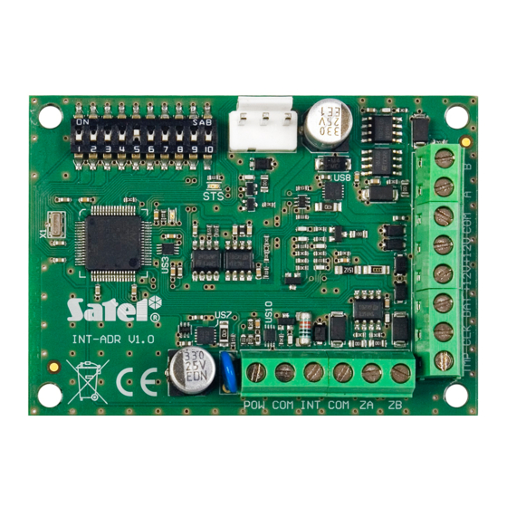
2. Electronics board
Explanations to Fig. 1:
DIP-switches (see: DIP-
connector for a dedicated power supply unit (e.g. APS-412).
STS LED indicating the status of power supply connected to the connector:
ON – power supply is working normally,
blinking – power supply is reporting a trouble.
).
SWITCHES
int-adr_en 05/14
Advertisement
Table of Contents

Related Manuals for Satel INT-ADR


Summary of Contents for Satel INT-ADR
- Page 1 ADDRESSABLE ZONE EXPANDER int-adr_en 05/14 The INT-ADR expander allows you to expand the system by adding up to 48 addressable zones. It supports detectors in which the CA-64 ADR-MOD addressable module is installed. The expander works with INTEGRA, INTEGRA Plus and CA-64 control panels.
- Page 2 INT-ADR SATEL LED indicating the status of communication with the control panel: ON – no communication with the control panel, blinking – communication with the control panel OK. Description of terminals: - +12 V DC dedicated power supply output for CA-64 ADR-MOD addressable modules and detectors.
- Page 3 INT-ADR Notes: The expander will be identified as INT-ADR / INT-ADRPS by INTEGRA / INTEGRA Plus control panels with firmware version 1.12 or newer. The switch 10 must be set in ON position, if the expander is connected to the following control panels: ...
- Page 4 INT-ADR SATEL The expander is designed for indoor installation. 1. Fasten the expander electronics board in the enclosure. 2. Using the DIP-switches, set the suitable expander address and define how it is to be identified. 3. Connect the CLK, DAT and COM terminals to the corresponding terminals of the control panel communication bus (see: installer manual for alarm control panel).
- Page 5 SATEL INT-ADR Use separate conductors to connect the power common for addressable modules and the power common for detectors. Connect to one of the detector alarm output terminals the same common ground which is connected to the addressable module. Connect the other terminal of alarm output to the blue wire of the addressable module.
- Page 6 INTEGRA / INTEGRA Plus control panel, it is possible to connect other modules to expand the number of zones, in addition to the INT-ADR expander. The zones in expanders with lower addresses are given lower numbers than those in expanders with higher addresses.
-
Page 7: Specifications
Dimensions ......................80 x 57 mm Weight..........................35 g The declaration of conformity may be consulted at www.satel.eu/ce SATEL sp. z o.o. • ul. Schuberta 79 • 80-172 Gdańsk • POLAND tel. + 48 58 320 94 00 info@satel.pl www.satel.eu...
Need help?
Do you have a question about the INT-ADR and is the answer not in the manual?
Questions and answers