Tosibox Lock 100 User Manual
Hide thumbs
Also See for Lock 100:
- User manual (48 pages) ,
- Quick start manual (2 pages) ,
- User manual (44 pages)

Subscribe to Our Youtube Channel
Related Manuals for Tosibox Lock 100


Summary of Contents for Tosibox Lock 100
- Page 1 USER MANUAL TOSIBOX Lock 100 ® TOSIBOX Lock 150 ® TOSIBOX ® Lock 200 TOSIBOX ® Lock 500 TOSIBOX ® Version 1.8...
-
Page 2: Table Of Contents
4.4 USB Modem settings for the Lock 4.5 Internal modem settings for Lock 500i 12. Declarations 4.6 WLAN settings for Lock 100, Lock 150 and Lock 500 4.7 Key connection settings for the Lock 4.8 Advanced settings for the Lock 4.9 Internet connection priorities... - Page 3 Congratulations for choosing TOSIBOX ® solution! It consists of modular components TECHNICAL SUPPORT that offer unlimited expandability and flexibility. All products are compatible with support@tosibox.com each other as well as internet connection, operator, and device agnostic. The system works both in internal and external networks.
-
Page 4: Regulatory Information
20 km from the centre of Ny-Ålesund, Svalbard, Norway. Tosibox Oy and its affiliates accept no responsibility for damages of any kind resulting from delays or errors in data transmitted or Lock 200: Office, residential and light industrial environment received using TOSIBOX ®... -
Page 5: Safety And Hazards
1.3 SAFETY AND HAZARDS At least 20 cm separation distance between the antennas and persons must be maintained at all times. Do not operate your Lock with internal or external cellular modem: • In areas where blasting is in progress •... -
Page 6: Informations Réglementaires
L’utilisation d’autre lorsque les équipements sont utilisés dans des conditions normales antenne annulera la conformité et n’est pas autorisée. dans des réseaux construits avec les règles de l’art, le TOSIBOX Lock ® avec un modem cellulaire ne devrait pas être utilisé dans les cas où... -
Page 7: Sécurité Et Dangers
1.3 SÉCURITÉ ET DANGERS Une distance minimale de 20 cm entre les antennes et les personnes doit être respectée à tout moment. N’utilisez pas votre Lock avec un modem cellulaire interne ou externe : • Dans les zones des explosions sont est en cours •... -
Page 8: Overview To Tosibox Key And Locks
Key and the Backup Key. Key user interface (installed from the Key device). In the image you can see TOSIBOX ® Lock devices which are matched with the TOSIBOX ® Key and the network devices connected to each TOSIBOX Lock. - Page 9 IP addresses for the Keys, Sub Keys and the network devices connected to LAN port(s) of the Lock. The Lock can also Lock 100/150 control network devices with fixed IP addresses. Lock settings can be changed via service port, encrypted TOSIBOX ® VPN connection local network SUB LOCK Lock 200 A Sub Lock is a Lock that has been converted to Sub Lock mode.
- Page 10 LOCK 100/150 CONTENT LOCK 200 CONTENT TOSIBOX ® Lock 200 TOSIBOX ® Lock 100/150 AC Adapter* AC Adapter* USB Cable DC Feed Plug DIN Rail Bracket Rubber Feet Cable Saddle Antennas (2) DC Feed Plug Ethernet Cable DIN Rail Bracket * AC Adapter model is subject to change according to the market area.
- Page 11 LOCK 500/500i CONTENT LOCK 500 POWER SOURCE KIT CONTENT TOSIBOX ® Lock 500/500i Ethernet Cable AC Power Source* AC Plug Adapters (LTE ports only in Lock 500i) LTE Antennas* WiFi Antennas (only Lock 500i) DC Conversion Cable Digital I/O SIM Card...
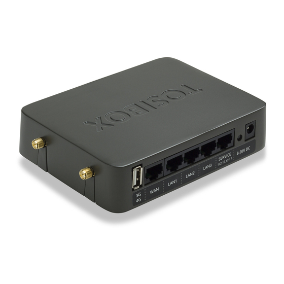
- Page 12 LOCK CONNECTIONS LOCK 100/150 1. USB Port for matching and USB Modem 2. WAN Port 3. LAN1 Port WLAN antenna ports 4. LAN2 Port 5. LAN3 Port 6. Service port 7. Reset button (not in use) 8. DC Power Input Led indicators: 9.
- Page 13 LOCK 200 1. DC Power Input 2. Reset button (not in use) 3. Power led indicator 4. Info led indicator 5. WAN Port 6. Service Port 7. LAN1 Port 8. LAN2 Port 9. LAN3 Port USB Port for matching and USB Modem...
- Page 14 LOCK 500/500i 1. SIM card slot LED indicators: 2. USB Port for matching and USB Modem 14. Power 3. Reset button for Service 15. Internet Port activation only 16. WiFi 4. Digital I/O -Connection 17. LTE Ethernet Connections: 5. LAN2 Port 6.
- Page 15 LOCK USER INTERFACE Status bar shows Locks and Keys Remotely controlled Login using “admin” Details of the remotely general information. devices controlled devices user. Green: Connected Password can be Green: Connected Red: Disconnected found on the bottom of Red: Disconnected the Lock...
-
Page 16: Getting Started
Lock has a working internet connection. 4. Connect the Key to your computer and install the Key software. Follow the section ”Deploying the Key”. 5. Secure TOSIBOX ® connection is now ready to be used for controlling and monitoring devices... -
Page 17: Tosibox ® Lock Instructions
4. TOSIBOX ® LOCK INSTRUCTIONS 4.1.1 DEPLOYING LOCK IN “LOCK MODE” 1. Before connecting device to Lock, connect to device per device manufacturer’s instructions on your PC and assign a new static IP address to device(s) from the Lock’s IP range printed on the bottom label of the Lock. -
Page 18: Deploying Lock In "Client Mode
• 3. Plug in a cable from the local network into one of the Lock’s LAN Client Mode is deactivated from the Lock’s web user interface ports and go! Server TOSIBOX ® VPN tunnel through Internet Router Lock ® TOSIBOX... -
Page 19: Connecting Locks
One example is a real-time protected connection between home and office. This is made with a Lock/Sub Lock solution (see accompanying image Connecting Locks). To Lock 100 and Lock 150 can be connected to up to 10 Sub Locks, to Lock 200 and Lock 500 can be connected to up to 50 Sub Locks. -
Page 20: Usb Modem Settings For The Lock
Choose “Settings” > “Software update” > uncheck the box “Auto- AND LOCK 500 update enabled”. On Lock 100, Lock 150 and Lock 500 you can configure the WLAN as 4.4 USB MODEM SETTINGS FOR THE LOCK Client (providing Internet access for the Lock) or as Access Point You can connect the Lock to the Internet with a USB Modem. -
Page 21: Advanced Settings For The Lock
In the event that the main connection is interrupted, On Lock 100, Lock 150 and Lock 200 a dedicated Service Port is the connection is automatically shifted to preselected backup available. -
Page 22: Mounting Instructions
Use only the screws included in the sales package. Using longer screws pose LOCK 100/150 QUICK INSTALLATION TO DIN RAIL a risk of damaging the device internal electronics. More versatile The bottom of the Lock has integrated hooks that allow a quick installation options to DIN rail, such as angle brackets are available installation to DIN rail with the LAN/WAN ports facing upwards. - Page 24 LOCK 200 USING THE RUBBER FEET LOCK 500 INSTALLATION ON THE TABLE Rubber feet included in the sales package can be installed in the The Lock can be placed standing vertically on its rubber feet. There bottom of the Lock for more convenient installation horizontally are vent holes on both sides of the device, designed to provide e.g.
- Page 25 LOCK 500 INSTALLATION TO DIN RAIL Picture 7. The Lock can be installed to DIN rail by using the integrated DIN rail bracket located in the backside of the device. Follow the sequence shown in picture 7. Removal is the reverse of installation. There are vent holes on both sides of the device, designed to provide cooling air passing thru 1.
-
Page 26: Input Powering Options
4.13 INPUT POWERING OPTIONS LOCK 200 Use the AC adapter included in the sales package. Alternatively, in LOCK 100/150 case the operating voltage of 8-27V DC +/-10% is available from Use the AC adapter included in the sales package. Alternatively,... - Page 27 The Lock is equipped with a 2 Amp internal fuse. In case of a device malfunction, the fuse is blown to protect the power circuitry. The fuse cannot be replaced by the user. In case of a blown internal fuse, do not open the device. Instead, contact your local Tosibox distributor for service.
-
Page 28: Lock 500 - Digital In/Out Port With 24V Dc Out
The Digital I/O port is equipped with a removable plug-in connector allows Internet connections. When port voltage is set low, there included in the TOSIBOX Lock 500 sales package. Remove the is no Internet access and the Lock visibility is “offline” for all Keys connector if needed and in case of a solid wire simply insert matched with it. - Page 29 VPN connection active – when Lock detects active VPN connection(s) from matched Keys, the port voltage is set high. When there are no active VPN connections, the port voltage is set low. VPN connection inactive – When there are no active VPN connections the port voltage is set high.
-
Page 30: Lock 500 - Digital I/O Sms Alert
The following settings need to be defined for input port 1 or input 4.16 LOCK 500 - DIGITAL I/O SMS ALERT port 2 or both: In order for the SMS alert feature to work, make sure to use a SIM Input port ≤X≥... - Page 31 Sending an SMS will happen in 1-10 seconds of the trigger. In case the SIM subscription does not support sending SMS, the messages will not be sent. Once the SMS has been sent by the Lock 500, the time to get it delivered to the destination is dependent on the Operator used.
-
Page 32: Tosibox Key Instructions
Yellow = The Key is connected to the Internet, but not to any found double click the executable file located in the Key’s folder (Setup_ Locks. Tosibox.exe). If your computer asks whether you want to allow Tosibox to make changes to your computer click yes. •... - Page 33 Virtual Central Lock with SW 2.2.0 or later • Central Lock with SW 2.3.0 or later • Lock 100 and Lock 200 with SW 3.3.0 or later • You will also need TOSIBOX ® Key SW v2.15.0 or later to complete the matching process.
-
Page 34: Renaming And Using Devices
5.2 RENAMING AND USING DEVICES This is the start window for the Key user interface. By clicking an extra menu opens. You can open the Lock user interface by double 1. Click “Open browser automatically when connected” to have the clicking the Lock icon on the left side of the window. - Page 35 1. You can open the browser user interface of the controlled device in “Open with browser (http)”. 2. You can connect to network sharing in “Open windows network share”. 3. You can open the remote desktop connection in “Open Remote Desktop Connection (RDP), if available”.
-
Page 36: Adding Extra Keys
Also, to connect to Locks with SoftKey, the software on the Lock needs to support SoftKeys. SoftKey is supported by these versions: 1. Lock 100 and Lock 200: SW v3.3.0 onwards 2. Central Lock and Virtual Central Lock: SW v2.3.0 onwards 3. Lock 500 / Lock 500i: all versions... - Page 37 3. On client computer: activate SoftKey: Make sure TOSIBOX ® 5. Define access rights for the new SoftKey by following the wizard. software v3.0.0 or later is installed on the PC. Start the software. Activate the SoftKey by choosing Devices > Activate SoftKey and enter the activation code.
- Page 38 ADDING SUB KEY 1. When a new Key is 2. Select the Lock(s)/Sub turned into a Sub Key, Lock(s) to which you choose ”Sub Key”, want to grant access provide a descriptive for the extra Key and name for it, and click choose ”Next”.
- Page 39 ADDING BACKUP KEY 1. Choose ”Backup Key” synchronized between and press ”Next”. the Backup Keys. All Keys and Locks are automatically 2. Confirm by pressing created. Press ”Close” button to exit the feature. ”Save”. 4. The Backup Keys can be managed later in the Key user interface 3.
- Page 40 EXTRA KEY USE CASE Sub Key Subkey...
-
Page 41: Remote Matching Of Extra Keys
PUK is needed. The PUK code is delivered 1. Insert the Key into the USB port of the computer and wait for the with the Key. Store it safely. TOSIBOX ® Key application to start. 2. Go to the ”Password” menu in the Key software and choose 2. -
Page 42: Tosibox ® Mobile Client Installation
6. TOSIBOX ® MOBILE CLIENT INSTALLATION 6.1 MOBILE CLIENT FOR ANDROID DEVICES 1. Download and install the 2. Open the TOSIBOX ® Key software 3. Go to the software menu and select by plugging a matched Key into Devices > Manage Keys. - Page 43 4. Select the mobile clients tab and click 5. Enter the name of your mobile device and 6. Select the Locks that you would like to Add new... click Next. access through your mobile device and click Next.
- Page 44 7. Open the TOSIBOX ® 8. Tap the screen to start 9. Scan the QR code displayed on your Mobile Client on your matching. computer or enter the matching code device. where prompted on your device.
- Page 45 10. Click Finish once the matching is 11. Create a password for 12. Connect to a Lock by complete. the mobile client. selecting its on/off icon.
- Page 46 13. Check the I trust this Now your mobile client is matched and can connect to the selected Locks application dialogue box and devices connected to them. and click OK. You can open network devices through your web browser (if available) by clicking the the appropriate globe icon.
-
Page 47: Mobile Client For Iphones And Ipads
6.2 MOBILE CLIENT FOR IPHONES AND IPADS 1. Download and install the 2. Open the TOSIBOX ® Key software 3. Go the software menu and select Devices TOSIBOX ® Mobile Client by plugging a matched Key into > Manage Keys. - Page 48 4. Select the Mobile Clients tab and click 5. Enter the name of your mobile device and 6. Select the Locks that you would like to Add new... click Next. access through your mobile device and click Next.
- Page 49 7. Open the TOSIBOX 8. Tap the screen to start 9. Scan the QR code displayed on your ® Mobile Client on your matching. computer or enter the matching code device. where prompted on your device.
- Page 50 10. Click Finish once the the matching is 11. Create a password for 12. Connect to a Lock by complete. the mobile client. selecting its on/off icon.
- Page 51 On the first time when 14. Now your mobile client is matched and can connect to the selected Locks and devices connected to them. connecting to a Lock, the user needs to authorize You can open network devices through your web browser (if available) the installation of the by clicking the the appropriate globe icon.
-
Page 52: Troubleshooting
Assurez-vous que les appareils contrôlés sont connectés au Lock. Device connections or the Lock connection in the window remains • Si vous êtes connecté via un réseau sans fil (Lock 100, Lock 150, Lock 500), red: connectez-vous au Lock par le port de service Ethernet. Vérifiez que la •... -
Page 53: Maintenance Instructions
8. CONSIGNES D’ENTRETIEN 8. MAINTENANCE INSTRUCTIONS Les équipements TOSIBOX doivent être traités avec précaution. En observant les ® TOSIBOX ® devices should be treated with care. By observing the instructions suivantes, vous profiterez de leurs performances maximales et aurez following instructions you can enjoy the maximum performance of l’assurance d’avoir une garantie optimale. -
Page 54: Technical Data
• VPN throughput up to 6 Mb/s (BF-CBC 128 bit) Physical properties TOSIBOX ® LOCK 100 POWER SOURCE • • 132 mm x 99 mm x 35.5 mm / 5.2” x 3.9”x 1.4” (L x W x H) Model ATS00ST-W120E •... - Page 55 TOSIBOX LOCK 150 ® Ports USB modem options • • 1x USB 2.0, type A, 500 mA maximum load allowed TB4GM2EU, TB4GM2AU • 1 x RJ-45 WAN conn., 10/100 Mb/s, auto-negotiation (MDI / MDI-X) WLAN • • 3 x RJ-45 LAN conn., 10/100 Mb/s, auto-negotiation (MDI / MDI-X) IEEE 802.11 b/g/n, max.
- Page 56 TOSIBOX ® LOCK 200 Ports USB modem options • • 1x USB 2.0, type A, 500 mA maximum load allowed TB4GM2EU, TB4GM2AU, for 3rd party options, please see: http://www.tosibox.com/support • 1 x RJ-45 WAN conn., 10/100 Mb/s, auto-negotiation (MDI / MDI-X) Powering requirements •...
- Page 58 TOSIBOX LOCK 500 ® Ports Physical properties • • 1x USB 2.0, type A, 500 mA maximum load allowed 110 mm x 58 mm x 127 mm / 4.33” x 2.28” x 5.0” (L x W x H) • •...
- Page 59 TOSIBOX LOCK 500 ® LTE frequency band support WCDMA frequency bands support Band Frequency (Tx) Frequency (Rx) Band Frequency (Tx) Frequency (Rx) Band 1 1920–1980 MHz 2110–2170 MHz Band 1 1920–1980 MHz 2110–2170 MHz Band 2 1850–1910 MHz 1930–1990 MHz Band 2 1850–1910 MHz 1930–1990 MHz Band 3 1710–1785...
- Page 60 TOSIBOX ® LOCK 500 TD-SCDMA Band 40 2300–2400 MHz (TDD) Band 41 2496–2690 MHz (TDD) Band 39 +23 dBm +- 1 dB • For bandwidth support details, see 3GPP TS 36.521-1 v11.3.0, table 5.4.2.1-1 Internal modem connection features (Continues) WCDMA frequency bands support TBL5iB* •...
- Page 61 TOSIBOX ® LOCK 500 Conducted TX (Transmit) Power tolerances WLAN • IEEE 802.11 b/g/n, max. 150 Mbps Parameter Cond. tr. p. Notes • WEP, WPA-PSK, WPA2-PSK, WPA-PSK/WPA2-PSK Mixed, WPA-EAP, WPA2-EAP TKIP/AES encryption LTE Band 1, 3, 5, 8, 18, •...
- Page 62 TOSIBOX POWER SOURCE SPECIFICATION ® Output Output Output Operating Operating Storage Storage Product Power model Input Frequency temperature humidity temperature humidity TBL1EU ATS00ST-W120E 100-240 V AC 47-63 Hz 12 V 0.6 A 7.2 W 0 °C … +40 °C / 20% - 80% RH -20 °C …...
- Page 63 TOSIBOX ® • 2048 bit RSA key in the cryptographic module • 4 GB or larger flash memory storage for TOSIBOX ® Key software and settings • USB 2.0 interface, type A • Standard CSP/PKCS#11 Supported operating systems: • Windows 10 •...
-
Page 64: Limited Warranty
10. LIMITED WARRANTY Subject to the exclusions set forth below, Tosibox Oy will repair or For Product Purchased in the USA: replace, at its option without charge, any TOSIBOX ® product which Performance of any obligation under this warranty may be... -
Page 65: Legal Notices
Tosibox se réserve le droit de réviser ce document ou de le retirer Tosibox products contain technology that is based on open source à... -
Page 66: Declarations
® EU DECLARATION OF CONFORMITY EU DECLARATION OF CONFORMITY Hereby, Tosibox Oy declares that the radio equipment type Lock Hereby, Tosibox Oy declares that the radio equipment type Lock 200 is in compliance with Directives 2014/35/EU and 2014/30/EU. 100 is in compliance with Directive 2014/53/EU. - Page 67 EU DECLARATION OF CONFORMITY This device complies with FCC part 15 of the FCC rules. Operation Hereby, Tosibox Oy declares that the radio equipment type Lock is subject to the following two conditions: (1) This device may 150 is in compliance with Directive 2014/53/EU.
- Page 68 TOSIBOX ® LOCK 150 Le présent appareil est conforme aux CNR d’Industrie Canada INDUSTRY CANADA STATEMENT applicables aux appareils radio exempts de licence. L’exploitation This device complies with Industry Canada license-exempt RSS est autorisée aux deux conditions suivantes : (1) l’appareil ne doit standard(s).
- Page 69 ® LOCK 500 EU DECLARATION OF CONFORMITY Hereby, Tosibox Oy declares that the radio equipment type Lock 500 is in compliance with Directive 2014/53/EU. The full text of the EU declaration of conformity is available at the following internet address: www.tosibox.com/documentation-and-downloads/...
- Page 70 Teknologiantie 12A FIN-90590 Oulu www.tosibox.com Copyright © Tosibox Oy 2019...
Need help?
Do you have a question about the Lock 100 and is the answer not in the manual?
Questions and answers