Summary of Contents for Toro GrandStand TURBO FORCE 74513
Page 1
With 48in, 52in, or 60in TURBO FORCE ® Cutting Unit Model No. 74513—Serial No. 403224659 and Up Model No. 74518—Serial No. 403260000 and Up Model No. 74519—Serial No. 403253175 and Up Model No. 79518—Serial No. 403254000 and Up *3425-452* A Register at www.Toro.com. Original Instructions (EN)
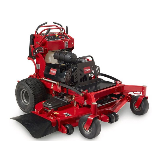
Page 2
It is a violation of California Public Resource Code Dealer or Toro Customer Service and have the model Section 4442 or 4443 to use or operate the engine on and serial numbers of your product ready. Figure 1 any forest-covered, brush-covered, or grass-covered...
Contents Removing the Fuel Tank ........35 Replacing the Fuel Filter ........35 Electrical System Maintenance ......36 Safety ............... 4 Electrical System Safety ........36 General Safety ........... 4 Servicing the Battery......... 36 Safety and Instructional Decals ......4 Servicing the Fuses ..........
Safety • Keep clear of the discharge opening. • Keep bystanders and children out of the operating area. Do not allow children to operate the machine. This machine has been designed in accordance with Allow only people who are responsible, trained, ANSI B71.4-2017.
Page 5
decal112-3858 112-3858 1. Read the Operator's 3. Remove the ignition key Manual. before adjusting the height of cut. 2. Read the instructions 4. Height-of-cut settings. before servicing or performing maintenance. decal131-1180 131-1180 3. Bagging setting 1. Read the Operator's Manual. 2.
Page 6
decal131-3521 131-3521 1. Height of cut decal131-3529 131-3529 1. Read the Operator's Manual for more information on maintenance intervals and procedures. decal131-3524 131-3524 3. Fluid level 1. Read the Operator's Manual. decal131-3536 2. Transmission fluid 131-3536 1. Battery 4. Parking brake 2.
Page 7
decal133-4641 133-4641 decal133-4604 1. Warning—do not carry passengers. 133-4604 1. Thrown object 3. Severing hazard of hand hazard—keep bystanders or foot—keep away from away from the machine. moving parts. 2. Thrown object hazard, 4. Entanglement open baffle—only operate hazard—keep away the machine with a baffle from moving parts;...
Page 8
decal136-5438 136-5438 1. Warning—read the Operator's Manual. 6. Thrown object hazard—keep bystanders away from the machine. 2. Warning—receive training before operating the machine. 7. Warning—engage the parking brake, shut off the engine, and remove the key from the switch before leaving the machine. 3.
Controls Product Overview Become familiar with all the controls before you start the engine and operate the machine (Figure Control Panel g031496 Figure 3 1. Anti-scalp roller (60-inch 7. Hydraulic tank decks only) 2. Front caster wheel 8. Fuel tank g031505 3.
Page 10
Power-Takeoff Switch (PTO) Motion-Control Levers Use the power-takeoff switch (PTO) to engage and Use the motion-control levers to drive the machine disengage mower blades or start and stop powered forward, reverse, and turn either direction (Figure attachments (Figure 4); refer to Operating the Mower-Blade-Control Switch (PTO) (page 15).
Authorized Service Dealer or authorized Toro required to operate the machine properly and distributor or go to www.Toro.com for a list of all safely. approved attachments and accessories. To ensure optimum performance and continued safety...
Using Stabilizer/Conditioner – Store fuel in an approved container and keep it out of the reach of children. Use fuel stabilizer/conditioner in the machine to keep • Fuel is harmful or fatal if swallowed. Long-term the fuel fresh longer when used as directed by the exposure to vapors can cause serious injury and fuel-stabilizer manufacturer.
Breaking in a New Machine Testing the Safety-Interlock System New engines take time to develop full power. Mower decks and drive systems have higher friction when Service Interval: Before each use or daily new, placing additional load on the engine. Allow 40 to 50 hours of break-in time for new machines to Test the safety-interlock system before you use the develop full power and best performance.
Avoid mowing in • Use only accessories and attachments approved wet conditions. by The Toro® Company. • Before you start the engine, ensure that all drives are in neutral, the parking brake is engaged, and Slope Safety you are in the operating position.
Operating the distance (twice the width of the machine) between the machine and any hazard. Use a walk-behind Mower-Blade-Control machine or a handheld tool to operate in these areas. Switch (PTO) • Avoid starting, stopping, or turning the machine on slopes.
Operating the Throttle Starting the Engine You can move the throttle control between F Important: Do not engage the starter for more positions (Figure 12). than 5 seconds at a time. If the engine fails to start, wait 15 seconds between attempts. Failure Always use the F position when engaging the PTO.
Shutting Off the Engine WARNING The operator platform is heavy and may cause injury when you raise or lower it. Carefully CAUTION lower or raise the operator platform, as Children or bystanders may be injured if they suddenly dropping it could injure you. move or attempt to operate the machine while it is unattended.
Driving Forward Disengage the parking brake; refer to Operating the Parking Brake (page 15). Move the motion-control levers to the center, unlocked position. g031026 Figure 17 1. Platform up 3. Pull the knob out to release the platform. 2. Platform down g030983 Figure 18 1.
Stopping the Machine To stop the machine, move the motion-control levers to neutral, then move the right motion-control lever into the N position, disengage the power EUTRAL LOCK takeoff (PTO), and turn the key to the O position. Engage the parking brake when you leave the machine;...
Adjusting the Height-of-Cut Adjusting the Anti-Scalp Rollers The height-of-cut can be adjusted from 38 to 127 mm (1-1/2 to 5 inches) in 6 mm (1/4 inch) increments. Models with a 60-Inch Deck Only Note: Using a height-of-cut under 51 mm (2 inches) Whenever you change the height-of-cut, adjust the increases the wear on the mower-deck belt.
Position B Use this position when bagging (Figure 25). g012676 Figure 23 1. Slot 2. Nut g012678 Figure 25 Positioning the Flow Baffle The following figures are for recommended use only. Adjustments vary by grass type, moisture content, Position C and the height of the grass.
Using Weights Using the Fuel-Shutoff Valve • Install weights to improve balance. You can add or remove weights to create optimized performance under different operating conditions and for your Close the fuel-shutoff valve for transport, maintenance, preference. and storage (Figure 27).
Pushing the Machine by Transporting the Machine Hand Use a heavy-duty trailer or truck to transport the machine. Use a full-width ramp. Ensure that the trailer The bypass valves allow you to push the machine by or truck has all the necessary brakes, lighting, and hand without the engine running.
Page 24
g031405 Figure 30 1. Back the machine up the 2. Walk the machine down ramp. the ramp. Shut off the engine, remove the key, and engage the parking brake. Tie down the machine near the front caster wheels and the rear bumper with straps, chains, cable, or ropes (Figure 31).
To ensure optimum performance and continued the engine running. safety certification of the machine, use only • Carefully release pressure from components with genuine Toro replacement parts and accessories. stored energy. Replacement parts and accessories made by • Check the parking brake operation frequently.
Maintenance Service Maintenance Procedure Interval • Replace the primary air filter (more often in dirty or dusty conditions). Every 300 hours • Check the inner air filter (more often in dirty or dusty conditions). • Adjust the caster-pivot bearing. • Check the hydraulic-fluid level. Every 500 hours •...
Lubrication Greasing the Front Caster Pivots Greasing the Machine Service Interval: Yearly Grease with No. 2 lithium or molybdenum grease. Grease type: Lithium or molybdenum grease Remove the dust cap and adjust the caster Disengage the PTO and set the parking brake. pivots;...
Greasing the Motion Remove the axle (with the other spacer nut still assembled to it) from the wheel assembly. Controls Pry out the seals, inspect bearings for wear or damage, and replace them if necessary. Service Interval: Yearly Pack the bearings with a general-purpose Grease the operator-presence-control balljoint and grease.
Engine Maintenance Engine Safety • Shut off the engine before checking the oil or adding oil to the crankcase. • Keep your hands, feet, face, clothing, and other body parts away from the muffler and other hot surfaces. Servicing the Air Cleaner g012996 Figure 36 Service Interval: Every 150 hours...
Inspecting the Filters Servicing the Engine Oil Inspect the safety filter. If it is dirty, replace both the safety and primary filters. Engine-Oil Specifications Important: Do not attempt to clean the Oil Type: Detergent oil (API service SJ or higher) safety filter.
Page 31
Disengage the PTO, move the motion-control levers to the N position, and EUTRAL LOCK engage the parking brake. Shut off the engine, remove the key, and wait for all moving parts to stop before leaving the operating position. Change the engine oil as shown in Figure g031514 g031514...
Page 32
Changing the Engine-Oil Filter Service Interval: Every 200 hours Note: Change the engine-oil filter more frequently when operating conditions are extremely dusty or sandy. Drain the oil from the engine; refer to Changing the Engine Oil (page 31). Change the engine-oil filter (Figure 42).
Servicing the Spark Plug Checking the Spark Plug Important: Do not clean the spark plug(s). Service Interval: Every 200 hours Always replace the spark plug(s) when it has a Make sure that the air gap between the center and black coating, worn electrodes, an oily film, or side electrodes is correct before installing the spark cracks.
Checking the Spark Fuel System Arrester Maintenance For Machines with a Spark Draining the Fuel Tank Arrester Service Interval: Every 50 hours You can drain the fuel tank by removing it and pouring the fuel out of the fill neck; refer to Removing the Fuel Tank (page 35).
Replacing the Fuel Filter Service Interval: Every 800 hours/Yearly (whichever comes first) Do not install a dirty filter if it is removed from the fuel line. Note: Wipe up any spilled fuel. Park the machine on a level surface, disengage the PTO, and engage the parking brake.
Electrical System Maintenance Electrical System Safety • Disconnect the battery or remove the spark-plug wire before making any repairs. Disconnect the negative terminal first and the positive terminal last. Connect the positive terminal first and negative last. • Charge the battery in an open, well-ventilated area, away from sparks and flames.
Page 37
Charging the Battery Installing the Battery Install the battery as shown in Figure WARNING Charging the battery produces gasses that can explode. Never smoke near the battery and keep sparks and flames away from battery. Important: Always keep the battery fully charged (1.265 specific gravity) to prevent battery damage when the temperature is below 0°C (32°F).
Servicing the Fuses Drive System Maintenance The electrical system is protected by fuses and requires no maintenance. If a fuse blows, check the component or circuit for a malfunction or short. Adjusting the Tracking Release the cushion from the rear of the machine.
Adjusting the Caster-Pivot Note: If you are unable to achieve proper tracking by adjusting the left control rod, contact Bearing your Authorized Service Dealer. Check that the machine does not creep from Service Interval: Every 500 hours/Yearly (whichever the neutral position with the park brakes comes first) disengaged.
Removing the Clutch Shim Remove the locknut and wheel bolt holding the caster wheel to the caster fork (Figure 56). Service Interval: Every 100 hours When the clutch brake has worn to the point where the clutch no longer engages consistently, you can remove the shim to extend the clutch life (Figure 57).
Page 41
Measure the gap between the rotor and is sometimes difficult to measure the true armature. If the gap is greater than 1 mm (0.04 gap. inch), proceed with the following steps: Loosen both brake mounting bolts 1/2 to 1 full turn as shown in Figure Note: Do not remove the brake pole from...
Checking the Wheel-Lug Cooling System Nuts Maintenance Service Interval: After the first 100 hours—Check the wheel-lug nuts. Cleaning the Air-Intake Check and torque the wheel-lug nuts to 115 to 142 Screen N∙m (85 to 105 ft-lb). Service Interval: Before each use or daily Before each use, remove any buildup of grass, dirt, or other debris from the cylinder and cylinder-head cooling fins, air-intake screen on the flywheel end,...
Brake Maintenance Belt Maintenance Testing the Parking Brake Checking the Belts Service Interval: Before each use or daily Service Interval: Every 100 hours—Check the mower-deck belt(s). Before each use, test the parking brake on both a level surface and slope. Check belts for cracks, frayed edges, burn marks, wear, signs of overheating, or any other damage.
g032680 Figure 66 1. Drain plug Allow the hydraulic fluid to drain from the machine. Remove the lower hydraulic hose (Figure 67). g031344 Figure 65 g031345 Figure 67 1. Lower hydraulic hose 3. Tension spring 2. Transmission belt Replacing the Transmission Belt Remove the tension spring (Figure...
Controls System Run the machine for 10 minutes and verify that the hydraulic fluid is at the correct level. Maintenance Adjusting the Motion-Control Levers If the motion-control levers do not align horizontally, adjust the motion-control levers. Park the machine on a level surface, disengage the PTO, and engage the parking brake.
Hydraulic System Important: Ensure that the flat portion of the cam does not go above a vertical position Specifications (right or left); otherwise you may damage the switch. Hydraulic Fluid Type: Toro ® HYPR-OIL ™ Repeat steps through for the left hydraulic fluid motion-control lever.
Remove the hydraulic-reservoir cap. Locate the drain plug in the bottom of each transmission and place a drain pan under the plugs (Figure 71). g031401 Figure 70 g032671 Figure 71 1. Hydraulic-tank cap 2. Fill level 1. Drain plug 2. Hydraulic filter Remove the cap from the filler neck (Figure 70).
Mower Deck Important: Use the fluid specified in Hydraulic System Specifications (page 46) Maintenance equivalent. Other fluids could cause system damage. Important: Monitor the level of fluid in the Servicing the Cutting hydraulic tank so that you do not overfill it. Blades Tighten the vent plugs.
Page 49
For best performance and continued safety conformance of the machine, use Checking for Bent Blades genuine Toro replacement blades. Replacement blades made by other manufacturers may result in Rotate the blades until the ends face forward non-conformance with safety standards.
g000552 Figure 76 1. Sharpen at original angle. Check the balance of the blade by putting it on a blade balancer (Figure 77). Note: If the blade stays in a horizontal position, the blade is balanced and can be used. Note: If the blade is not balanced, file some metal off the end of the sail area only...
Page 51
Measure at the B and C locations from a level Rotate the top bolt of the yokes to adjust the surface to the cutting edge of blade tips (Figure height of the mower deck (Figure 80). 79). Note: Rotate the bolts clockwise to raise the deck;...
Page 52
g000975 Figure 83 g031519 2. Measure the blade at point 1. Measure from a level Figure 82 surface 1. Top bolt 4. Side nut 2. Jam nut 5. Adjust these yokes to If the measurement is not correct, locate the adjust the front side of the front 2 yokes on the machine (Figure...
Adjusting the Deck-Lift Replacing the Grass Spring Deflector Note: Adjusting the compression spring alters how WARNING much the deck floats and the amount of effort needed An uncovered discharge opening could allow to lift the deck when using the height-of-cut lever. the machine to throw objects toward you or •...
Cleaning Storage Storage Safety Cleaning under the Mower • Let the engine cool before storing the machine. Deck • Do not store the machine or fuel near flames or drain the fuel indoors. Service Interval: Before each use or daily Before each use or daily Cleaning and Storage Remove the grass buildup under the mower daily.
Page 55
Important: Do not store fuel containing stabilizer/conditioner longer than the duration recommended by the fuel-stabilizer manufacturer. Remove the spark plug(s) and check its condition; refer to Servicing the Spark Plug (page 33). With the spark plug(s) removed from the engine, pour 15 ml (2 tablespoons) of engine oil into the spark-plug hole, and use the starter to crank the engine and distribute the oil inside the cylinder.
Troubleshooting Problem Possible Cause Corrective Action The engine does not start, starts hard, or 1. The fuel tank is empty or the shutoff 1. Fill the fuel tank with fuel and open the fails to keep running. valve is closed. valve 2.
Page 57
Problem Possible Cause Corrective Action The cutting height is uneven. 1. Blade(s) are not sharp. 1. Sharpen the blade(s). 2. Cutting blade(s) is/are bent. 2. Install new cutting blade(s). 3. The mower deck is not level. 3. Level the mower deck side-to-side position.
Page 60
While the exposure from Toro products may be negligible or well within the “no significant risk” range, out of an abundance of caution, Toro has elected to provide the Prop 65 warnings. Moreover, if Toro does not provide these warnings, it could be sued by the State of California or by private parties seeking to enforce Prop 65 and subject to substantial penalties.
Need help?
Do you have a question about the GrandStand TURBO FORCE 74513 and is the answer not in the manual?
Questions and answers