Table of Contents
Advertisement
Quick Links
Advertisement
Table of Contents

Related Manuals for LifeGear 27015


Summary of Contents for LifeGear 27015
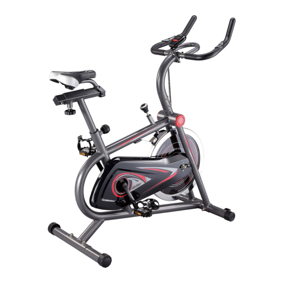
- Page 1 Spinning Bike ITEM NO.: 27015 OWNER’S MANUAL IMPORTANT: Read all instructions carefully before using this product. Retain this owner’s manual for future reference. The specifications of this product may vary from this photo and are subject to change without prior notice.
-
Page 2: Table Of Contents
TABLE OF CONTENTS WARRANTY ------------------------------------------------------------------------------- 2 IMPORTANT SAFETY INSTRUCTIONS ------------------------------------------- 3 PARTS LIST ------------------------------------------------------------------------------- 4 HARDWARE LIST ----------------------------------------------------------------------- 6 TOOLS -------------------------------------------------------------------------------------- 6 EXPLODED VIEW ----------------------------------------------------------------------- 7 ASSEMBLY INSTRUCTIONS -------------------------------------------------------- 8 HOW TO MOVE THE BIKE ------------------------------------------------------------ 15 OPERATING THE COMPUTER ------------------------------------------------------ 16 ADJUSTMENTS -------------------------------------------------------------------------- 17 EMERGENCY STOP -------------------------------------------------------------------- 19 MAINTENANCE -------------------------------------------------------------------------- 20... -
Page 3: Warranty
ONE YEAR LIMITED WARRANTY LifeGear Inc. warrants to the original purchaser that this product is free from defects in material and workmanship when used for the purpose intended, under the conditions that it has been installed and operated in accordance with LifeGear's Owner's Manual. LifeGear's obligation under this warranty is limited to replacing or repairing free of charge, any parts which may prove to be defective under normal home use. -
Page 4: Important Safety Instructions
IMPORTANT SAFETY INSTRUCTIONS Basic precautions should always be followed, including the following safety instructions when using this spinning bike. Read all instructions before using this spinning bike. Read all the instructions in this manual and do warm up exercises before using this equipment. -
Page 5: Parts List
PARTS LIST Description Qty No. Description 001 Main Frame 1 025 Seat Cushion 002 Handlebar Post 1 026 Seat Sliding Tube Cover Cross Recessed Pan Head Self 003 Seat Post 1 027 Tapping Screw ST4.2x15 004 Seat Sliding Tube 1 028 Computer XT-1027 005 Handlebar 1 029 Handlebar End Cap Ø28 Handlebar Foam Grip... - Page 6 PARTS LIST Description Description 049 Brake Pad Plate 119x30x35 068 Sleeve Ø18xØ12x4 050 Brake Pad 115x25x6 069 Chain Cross Recessed Pan Head Bolt 051 Hexagon Head Bolt M5x35 M6x10 052 Small Spring Plate 071 Crank Cover 053 Washer Ø5xØ10x1.0 072 Hexagon Flange Nut M10x1.25x9 054 Cap Nut M5 073 Left Crank 9/16"...
-
Page 7: Hardware List
HARDWARE LIST (9) Carriage Bolt (10) Curve Washer (11) Cap Nut 4 PCS 4 PCS 4 PCS (31) Hexagon Socket (32) Spring Washer (33) Washer Pan Head Cap Bolt 4 PCS 4 PCS 4 PCS (34) Cap Nut 4 PCS TOOLS Allen Wrench S6 Multi Hex Tool... -
Page 8: Exploded View
EXPLODED VIEW 61 61 62 63 63 63 72 71 35 36 32 38... -
Page 9: Assembly Instructions
ASSEMBLY INSTRUCTIONS STEP 1 Use the Multi Hex Tool with Phillips Screwdriver to loosen the screws in the Main Frame (1). Remove the screws and cardboard tubes from the Main Frame (1). Hardware: (9) Carriage Bolt 2 PCS 11 10 (10) Curve Washer 2 PCS (11) Cap Nut... - Page 10 Hardware: (9) Carriage Bolt 2 PCS (10) Curve Washer 2 PCS (11) Cap Nut 2 PCS STEP 3 Position the Rear Stabilizer (8) behind the Main Frame (1) and align bolt holes. Attach the Rear Stabilizer (8) onto the rear of the Main Frame (1) with two Carriage Bolts (9), two Curve Washers (10), and two Cap Nuts (11).
- Page 11 STEP 4 The Cranks and Pedal Shafts are marked with the letter R (Right) and L (Left) to denote the side of the spinning bike they are on. Insert the pedal shaft of Left Foot Pedal (18) into threaded hole in the Left Crank (73). Turn the pedal shaft by hand in the counterclockwise direction until snug.
- Page 12 STEP 6 Insert the Seat Post (3) into the tube of the Main Frame (1) and align round knob holes. Then attach the Round Knob (17) onto the tube of the Main Frame (1) by turning it in a clockwise direction to tighten the Seat Post (3) in the suitable position. STEP 7 Remove six Hexagon Socket Pan Head Cap Bolts (37), six Spring Washers (32), and six Curve Washers (38) from the Main Frame (1).
- Page 13 37 32 37 32 38 STEP 8 Insert the Handlebar Post (2) onto the tube of the Main Frame (1) and secure with six Hexagon Socket Pan Head Cap Bolts (37), six Spring Washers (32), and six Curve Washers (38) that were removed. Tighten bolts with the Allen Wrench provided.
- Page 14 STEP 9 Position the Computer Holder (6) and Handlebar (5) onto the top end of the Handlebar Post (2) and align bolt holes. Attach the Computer Holder (6) Handlebar (5) onto the top end of the Handlebar Post (2) with four Hexagon Socket Pan Head Cap Bolts (31), four Spring Washers (32), four Washers (33), and four Cap Nuts (34).
- Page 15 STEP 10 A. Slide the Computer (28) onto the Computer Holder (6) until it locks into place. B. Connect both Hand Pulse Sensor Wires (35) from the Handlebar (5) to the wires that come from the Computer (28). C. Connect the Sensor Wire (43) to the wire that comes from the Computer (28).
-
Page 16: How To Move The Bike
HOW TO MOVE THE BIKE Handlebar Transport Wheel This spinning bike has a pair of Transport Wheels built into the front stabilizer and can be carefully tilted onto its Transport Wheels for easy moving and storage. To move the spinning bike, stand in front of the bike, firmly grasp the Handlebar with both hands. -
Page 17: Operating The Computer
OPERATING THE COMPUTER USING YOUR COMPUTER The computer can be activated by pressing the button or by pedaling. If you leave the equipment idle for 4-5 minutes, the power will turn off automatically. BUTTON FUNCTIONS: Press the button to select the functions of the computer. Press and hold the button for 3 seconds to reset all data values to zero. -
Page 18: Adjustments
ADJUSTMENTS Rear Stabilizer End Cap Adjusting the Rear Stabilizer End Cap Turn the Rear Stabilizer End Cap on the rear stabilizer as needed to level the spinning bike. Tension Knob Adjusting the Tension Knob To increase the tension, turn the Tension Knob in a clockwise direction. To decrease the tension, turn the Tension Knob in a counterclockwise direction. - Page 19 Round Knob Adjusting the Seat Height 1. Loosen the Round Knob by turning counterclockwise direction until it can be pulled out. 2. Pull out the Round Knob and then slide the Seat Post up or down direction to the suitable position.
-
Page 20: Emergency Stop
Seat Adjustment Knob Adjusting the Seat Forward or Back 1. Loosen the Seat Adjustment Knob by turning counterclockwise direction. 2. Slide the Seat Sliding Tube forth or back direction to the suitable position. 3. Lock the Seat Sliding Tube in place by turning the Seat Adjustment Knob clockwise direction. -
Page 21: Maintenance
MAINTENANCE CLEANING After each exercise, ensure that the unit is wiped down and any sweat is removed from the spinning bike. The spinning bike can be cleaned with a soft clean cloth. Do not use abrasives or solvents on plastic parts. INSPECTION Inspect the frames for rust or other damage. -
Page 22: Warm Up And Cool Down Routine
WARM UP AND COOL DOWN ROUTINE The WARM-UP is an important part of any workout. The purpose of warming up is to prepare your body for exercise and to minimize injuries. Warm up for two to five minutes before aerobic exercising. It should begin every session to prepare your body for more strenuous exercise by heating up and stretching your muscles, increasing your circulation and pulse rate, and delivering more oxygen to your muscles. - Page 23 QUADRICEPS STRETCH With one hand against a wall for balance, reach behind you and pull your right foot up. Bring your heel as close to your buttocks as possible. Hold for 15 counts and repeat with left foot. INNER THIGH STRETCH Sit with the soles of your feet together and your knees pointing outward.
Need help?
Do you have a question about the 27015 and is the answer not in the manual?
Questions and answers