Table of Contents
Advertisement
Quick Links
Advertisement
Table of Contents

Related Manuals for LifeGear Jupiter


Summary of Contents for LifeGear Jupiter
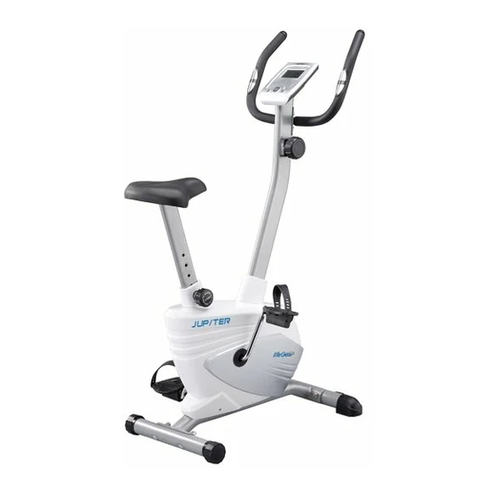
- Page 1 JUPITER, MAGNETIC UPRIGHT BIKE ITEM NO: 20720 OWNER’S MANUAL IMPORTANT: Read all instructions carefully before using this product. Retain this owner’s manual for future reference. The specifications of this product may vary from this photo, subject to change without notice.
-
Page 2: Table Of Contents
TABLE OF CONTENTS WARRANTY ------------------------------------------------------------------------------- 2 IMPORTANT SAFETY INSTRUCTIONS ------------------------------------------- 3 PARTS LIST ------------------------------------------------------------------------------- 4 HARDWARE PACKING LIST --------------------------------------------------------- 5 TOOLS -------------------------------------------------------------------------------------- 5 OVERVIEW DRAWING ----------------------------------------------------------------- 6 ASSEMBLY INSTRUCTIONS --------------------------------------------------------- 7 OPERATING THE COMPUTER ------------------------------------------------------ 11 ADJUSTMENTS -------------------------------------------------------------------------- 13 MAINTENANCE -------------------------------------------------------------------------- 14 TROUBLESHOOTING ------------------------------------------------------------------ 14 WARM UP AND COOL DOWN ROUTINE ----------------------------------------- 15... -
Page 3: Warranty
ONE YEAR LIMITED WARRANTY LifeGear Inc. warrants to the original purchaser that this product is free from defects in material and workmanship when used for the purpose intended, under the conditions that it has been installed and operated in accordance with LifeGear's Owner's Manual. LifeGear's obligation under this warranty is limited to replacing or repairing free of charge, any parts which may prove to be defective under normal home use. -
Page 4: Important Safety Instructions
IMPORTANT SAFETY INSTRUCTIONS Basic precautions should always be followed, including the following important safety instructions when using this equipment: Read all instructions before using this equipment. Read all instructions and follow it carefully before using this equipment. Make sure the equipment is properly assembled and tightened before use. -
Page 5: Parts List
PARTS LIST Description Qty No. Description 001 Main Frame Ø50x1.5t 1 030 Cover Cap 002 Handlebar Ø25x1.5t 1 031 Handlebar Post Cover 003 Handlebar Post 70x30x1.5t 1 032 Seat Post Cover 004 Rear Stabilizer Ø50x1.5x380mm 1 033 Extension Sensor Wire L=1100mm 005 Flywheel Ø230 1 034 Cap Nut M10 006 Front Stabilizer Ø50x1.5x430mm... -
Page 6: Hardware Packing List
PARTS LIST Description Qty No. Description 059 Eyebolt M6x36 2 062 Bolt M6x48mm 060 Tension Bracket 2 063 Nylon Nut M6 061 Transport Wheel Ø23xØ6x32 HARDWARE PACKING LIST (34) Cap Nut M10 (35) Carriage Bolt (36) Big Curve Washer Ø10 4 PCS M10x65mm 4 PCS... -
Page 7: Overview Drawing
OVERVIEW DRAWING... -
Page 8: Assembly Instructions
ASSEMBLY INSTRUCTIONS Tool: Multi Hex Tool 1. Front/Rear Stabilizers and Right/Left Foot Pedals Installation Position the Front Stabilizer (6) in front of the Main Frame (1) and align bolt holes. Attach the Front Stabilizer (6) onto the front curve of the Main Frame (1) with two M10 Cap Nuts (34), two M10x65mm Carriage Bolts (35), and two Ø10 Big Curve Washers (36). - Page 9 Tool: Multi Hex Tool 2. Seat Post, Seat Post Cover, and Seat Cushion Installation Remove three Ø16xØ8x1.5t Washers (38) and three M8 Nylon Nuts (42) from underside of the Seat Cushion (27). Remove nylon nuts and washers with the Multi Hex Tool provided. Guide bolts on underside of the Seat Cushion (27) through holes on top of the Seat Post (25), attach with three removed Ø16xØ8x1.5t Washers (38) and M8 Nylon Nuts (42).
- Page 10 Tool: Allen Wrench with Phillips Screwdriver 5mm 3. Handlebar Post, Handlebar Post Cover, and Tension Control Knob Installation Remove five M8x16mm Bolts (24), four Ø16xØ8x1.5t Washers (38), and one Ø20xØ8x1.5t Curve Washer (37) from the tube of the Main Frame (1). Remove bolts with the 5mm Allen Wrench with Phillips Screwdriver provided.
- Page 11 up and force it into the gap of metal bracket of Tension Cable (54), see Figure B. Attach the Tension Control Knob (7) onto the Handlebar Post (3) with the Ø5xØ20x1.5t Big Washer (46) and M5x20 Bolt (57) that were removed. Tighten bolt with the 5mm Allen Wrench with Phillips Screwdriver provided.
-
Page 12: Operating The Computer
OPERATING THE COMPUTER SPECIFICATIONS: TMR (TIMER) ---------------------------------- 0:00-99:59 MIN: SEC SPD (SPEED) --------------------------------- 0.0-999.9 KM/H DIS (DISTANCE) ----------------------------- 0.0-999.9 KM CAL (CALORIES) ----------------------------- 0.0-999.9 KCAL ODO (ODOMETER) ------------------------- 0-9999 KM RPM --------------------------------------------- 0-9999 REVOLUTIONS/MIN P (PULSE) ------------------------------------- 40-239 BEATS/MIN USING YOUR COMPUTER The computer can be activated by pressing the buttons or by pedaling. - Page 13 DIS (DISTANCE): Displays the accumulative distance traveled during workout. You may also pre-set target distance in STOP mode before training. To set DIS (DISTANCE) press the MODE button until you see the DIS on the screen. Press the SET button, DIS begin blinking.
-
Page 14: Adjustments
ADJUSTMENTS Adjusting the Tension Control Knob To increase the load, turn the tension control knob in a clockwise direction. To decrease the load, turn the tension control knob in a counterclockwise direction. Tension Control Knob Adjusting the Rear Stabilizer End Cap Turn the rear stabilizer end cap on the rear stabilizer as needed to level the upright bike. -
Page 15: Maintenance
MAINTENANCE Cleaning The upright bike can be cleaned with a soft cloth and mild detergent. Do not use abrasives or solvents on plastic parts. Please wipe your perspiration off the upright bike after each use. Be careful not get excessive moisture on the computer display panel as this might cause an electrical hazard or electronics to fail. -
Page 16: Warm Up And Cool Down Routine
WARM UP AND COOL DOWN ROUTINE The WARM-UP is an important part of any workout. The purpose of warming up is to prepare your body for exercise and to minimize injuries. Warm up for two to five minutes before aerobic exercising. It should begin every session to prepare your body for more strenuous exercise by heating up and stretching your muscles, increasing your circulation and pulse rate, and delivering more oxygen to your muscles. - Page 17 QUADRICEPS STRETCH With one hand against a wall for balance, reach behind you and pull your right foot up. Bring your heel as close to your buttocks as possible. Hold for 15 counts and repeat with left foot. INNER THIGH STRETCH Sit with the soles of your feet together and your knees pointing outward.
Need help?
Do you have a question about the Jupiter and is the answer not in the manual?
Questions and answers