Table of Contents
Advertisement
Quick Links
Advertisement
Table of Contents

Related Manuals for LifeGear 20697


Summary of Contents for LifeGear 20697
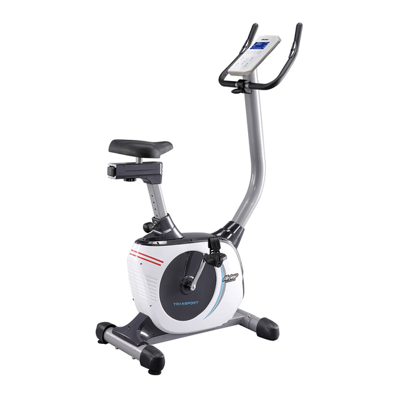
- Page 1 TRANSPORT PC PRO MAGNETIC UPRIGHT BIKE ITEM NO.: 20697 OWNER’S MANUAL IMPORTANT: Read all instructions carefully before using this product. Retain this owner’s manual for future reference. The specifications of this product may vary from this photo, subject to change without notice.
-
Page 2: Table Of Contents
TABLE OF CONTENTS WARRANTY ------------------------------------------------------------------------------- 2 IMPORTANT SAFETY INSTRUCTIONS ------------------------------------------- 3 PARTS LIST ------------------------------------------------------------------------------- 4 HARDWARE PACKING LIST --------------------------------------------------------- 6 TOOLS -------------------------------------------------------------------------------------- 6 OVERVIEW DRAWING ----------------------------------------------------------------- 7 ASSEMBLY INSTRUCTIONS --------------------------------------------------------- 8 OPERATING THE COMPUTER ------------------------------------------------------ 14 ADJUSTMENTS -------------------------------------------------------------------------- 19 MAINTENANCE -------------------------------------------------------------------------- 20 TROUBLESHOOTING ------------------------------------------------------------------ 20 WARM UP AND COOL DOWN ROUTINE ----------------------------------------- 21... -
Page 3: Warranty
ONE YEAR LIMITED WARRANTY LifeGear Inc. warrants to the original purchaser that this product is free from defects in material and workmanship when used for the purpose intended, under the conditions that it has been installed and operated in accordance with LifeGear's Owner's Manual. LifeGear's obligation under this warranty is limited to replacing or repairing free of charge, any parts which may prove to be defective under normal home use. -
Page 4: Important Safety Instructions
IMPORTANT SAFETY INSTRUCTIONS Basic precautions should always be followed, including the following important safety instructions when using this equipment. Read all instructions before using this equipment. Read all instructions and follow it carefully before using this equipment. Make sure the equipment is properly assembled and tightened before use. -
Page 5: Parts List
PARTS LIST Description Qty No. Description 001 Computer (SM-3710) 1 023 Seat Cushion DD-353T Computer Extension Wire I Seat Sliding Tube End Cap 1 024 (L=500 mm) 38x38 Computer Extension Wire II 1 025 Nylon Nut M8 (L=1000 mm) 004 Handlebar Ø25x1.5t 1 026 Washer Ø16xØ8x1.5t Handlebar Foam Grip... - Page 6 PARTS LIST Description Qty No. Description 045 Big Curve Washer Ø8xØ20x2.0t 4 060 Eyebolt M6x36 046 Cap Nut M8 2 061 Flywheel Ø250 047 Washer Ø6xØ12x1.0t 8 062 Spring Clip Ø17 048 Main Frame 1 063 Bearing 6003ZZ 049R Right Foot Pedal YH-30X 1 064 Sensor with Wire L=750 mm 049L Left Foot Pedal YH-30X 1 065 Belt Pulley 260J6...
-
Page 7: Hardware Packing List
HARDWARE PACKING LIST (7) Cross Recessed Pan Head (27) Cross Recessed Pan Head Tapping Screw ST4.2x20 Tapping Screw ST2.9x16 2 PCS 5 PCS (45) Big Curve Washer (44) Carriage Bolt M8x90 Ø8xØ20x2.0t 2 PCS 4 PCS (46) Cap Nut M8 (72) Hexagon Socket Pan 2 PCS Head Cap Bolt M8x90... -
Page 8: Overview Drawing
OVERVIEW DRAWING... -
Page 9: Assembly Instructions
ASSEMBLY INSTRUCTIONS Tool: Multi Hex Tool with Phillips Screwdriver S10, S13, S14, S15 Allen Wrench S6 1. Front/Rear Stabilizers and Right/Left Foot Pedals Installation Position the Front Stabilizer (43) in front of Main Frame (48) and align bolt holes. Attach the Front Stabilizer (43) onto the front curve of the Main Frame (48) with two M8x90 Carriage Bolts (44), two Ø8xØ20x2.0t Big Curve Washers (45), and two M8 Cap Nuts (46). - Page 10 Hardware: (45) Big Curve Washer (44) Carriage Bolt Ø8xØ20x2.0t M8x90 4 PCS 2 PCS (46) Cap Nut M8 (72) Hexagon Socket Pan 2 PCS Head Cap Bolt M8x90 2 PCS...
- Page 11 Tool: Multi Hex Tool with Phillips Screwdriver S10, S13, S14, S15 Multi Hex Tool S10, S13, S17, S19 2. Seat Post, Seat Cushion, Seat Sliding Tube, and Seat Sliding Tube Covers Installation Slide the Seat Post Cover (32) onto the tube of the Main Frame (48). Insert the Seat Post (31) into the Seat Post Bushing (34) on the tube of the Main Frame (48) and then attach the Seat Height Adjustment Knob (33) onto the tube of the Main Frame (48) by turning it in a clockwise direction with Multi Hex Tool provided to lock the Seat Post (31) in the suitable...
- Page 12 Tool: 19 20 Allen Wrench S6 3. Handlebar Post and Handlebar Post Cover Installation Remove six M8x15 Hexagon Socket Pan Head Cap Bolts (19) and six Ø8xØ16x1.5t Curve Washers (20) from the Main Frame (48). Remove bolts and curve washers with the S6 Allen Wrench provided.
- Page 13 Tool: Multi Hex Tool with Phillips Screwdriver S10, S13, S14, S15 4. Handlebar and Computer Installation Insert the Hand Pulse Sensor Wires (6) into the hole on the Handlebar Post (14) then pull them out from the top end of the Handlebar Post (14). Place the Handlebar (4) through clamp on the Handlebar Post (14) with hand pulse sensors facing the seat.
- Page 14 5. AC Adapter Installation Plug one end of the AC Adapter (18) into the power jack of the Power Supply Wire (17) on the back of the Left Shroud (54L). Before plugging in, make sure to check carefully the specifications on the Adapter. Plug the other end of the AC Adapter (18) into the electrical wall outlet.
-
Page 15: Operating The Computer
OPERATING THE COMPUTER COMPUTER BUTTON FUNCTIONS: START/STOP: To start and stop the workout session. UP: Press the UP button to select the exercise mode of MANUAL, PROGRAM, USER PROGRAM, and H.R.C., and WATT PROGRAM. Press the UP button to make upward for function values adjustment on different training mode. - Page 16 BODY FAT: To test your body fat percentage and BMI. Press the BODY FAT button and then grip the hand pulse sensors with both hands for a few seconds, and the screen will display your BMI, body fat percentage, and fat symbol. NOTE: Body Fat Percentage is an estimate based on the sex, age, height, and weight input, and is to be used as a guide only.
- Page 17 U1 with a long BI tone, press the Up or DOWN button to select USER number (U1-U4) and press the MODE button to confirm the user number. Then input USER data (sex, age, height, and weight) by pressing the Up or DOWN button. Press the MODE button to confirm the USER data.
- Page 18 TRAINING IN PROGRAM MODE: Press the UP or DOWN button to select the PROGRAM mode and then press the MODE button for confirmation. There are 12 pre-set programs that offer you a variety of workout options. To select a program, use the UP or DOWN button to select one of the pre-set programs.
- Page 19 If user selects H.R.C. TAG and the split window of PULSE will display 100 for the target heart rate. Press the MODE button for confirmation. User may press the UP or DOWN button to set desired Target Heart Rate. At this point you can press the START/STOP button to start your workout or you can set a “TIME goal”...
-
Page 20: Adjustments
ADJUSTMENTS Adjusting the Adjustable Leveler Turn the adjustable leveler on the rear stabilizer as needed to level the upright bike. Adjustable Leveler Adjusting the Seat Forward or Back Turn the seat adjustment knob to loosen the seat sliding tube. Slide the seat sliding tube forward or back to desired position and turn seat adjustment knob to tighten. -
Page 21: Maintenance
MAINTENANCE Cleaning The upright bike can be cleaned with a soft clean damp cloth. Do not use abrasives or solvents on plastic parts. Please wipe your perspiration off the upright bike after each use. Be careful not to get excessive moisture on the computer display panel as this might cause an electrical hazard or electronics to fail. -
Page 22: Warm Up And Cool Down Routine
WARM UP AND COOL DOWN ROUTINE The WARM-UP is an important part of any workout. The purpose of warming up is to prepare your body for exercise and to minimize injuries. Warm up for two to five minutes before aerobic exercising. It should begin every session to prepare your body for more strenuous exercise by heating up and stretching your muscles, increasing your circulation and pulse rate, and delivering more oxygen to your muscles. - Page 23 QUADRICEPS STRETCH With one hand against a wall for balance, reach behind you and pull your right foot up. Bring your heel as close to your buttocks as possible. Hold for 15 counts and repeat with left foot. INNER THIGH STRETCH Sit with the soles of your feet together and your knees pointing outward.
Need help?
Do you have a question about the 20697 and is the answer not in the manual?
Questions and answers