Table of Contents
Advertisement
Quick Links
Advertisement
Table of Contents

Related Manuals for LifeGear 27890


Summary of Contents for LifeGear 27890
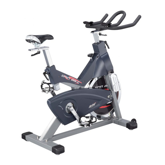
- Page 1 SPIN BIKE ITEM NO.: 27890 OWNER’S MANUAL IMPORTANT: Read all instructions carefully before using this product. Retain this owner’s manual for future reference. The specifications of this product may vary from this photo and are subject to change without prior notice.
-
Page 2: Table Of Contents
TABLE OF CONTENTS WARRANTY ------------------------------------------------------------------------------- 2 IMPORTANT SAFETY INSTRUCTIONS ------------------------------------------- 3 PARTS LIST ------------------------------------------------------------------------------- 4 HARDWARE AND TOOLS PACK ---------------------------------------------------- 6 EXPLODED VIEW ----------------------------------------------------------------------- 7 ASSEMBLY INSTRUCTIONS --------------------------------------------------------- 8 HOW TO MOVE THE BIKE ------------------------------------------------------------ 14 ADJUSTMENTS -------------------------------------------------------------------------- 15 EMERGENCY STOP -------------------------------------------------------------------- 18 MAINTENANCE -------------------------------------------------------------------------- 18 WARM UP AND COOL DOWN ROUTINE ----------------------------------------- 19... -
Page 3: Warranty
ONE YEAR LIMITED WARRANTY LifeGear Inc. warrants to the original purchaser that this product is free from defects in material and workmanship when used for the purpose intended, under the conditions that it has been installed and operated in accordance with LifeGear's Owner's Manual. LifeGear's obligation under this warranty is limited to replacing or repairing free of charge, any parts which may prove to be defective under normal home use. -
Page 4: Important Safety Instructions
IMPORTANT SAFETY INSTRUCTIONS Basic precautions should always be followed, including the following safety instructions when using this bike. Read all instructions before using this bike. Read all the instructions in this manual and do warm up exercises before using this equipment. -
Page 5: Parts List
PARTS LIST Description Qty No. Description Adjustable Leveler 4 026 Washer Ø5 Ø40x35/M8x25 002 Nylon Nut M6 4 027 Water Bottle Holder Cup Head Square Neck Bolt 4 028 Handlebar Post 310x200x53 M8x52 004 Rear Stabilizer 545x90x70 1 029 Handlebar 480x380x80 005 Stabilizer End Cap 86x86x58 4 030 Crank Cover Ø28x6.5 006 Washer Ø8... - Page 6 PARTS LIST Description Description 052 Brake Pad 113x25x8 068 Bearing 6001ZZ 053 Brake Bracket 200x47x30 069 Flywheel Ø453x29 (20 kgs) 054 Spring Ø2.2 070 Axle Ø12x160 055 Spring Cap 32x23x2 071 Hexagon Flange Nut M12x1.25 056 Cap Nut M6 072 Plastic Bushing 38x38x1.5 057 Washer Ø10 073 Left Decorative Cover 058 Brake Block 14x9x14...
-
Page 7: Hardware And Tools Pack
HARDWARE AND TOOLS PACK Multi Hex Tool with Phillips Screwdriver 1 PC (3) Cup Head Square Neck Bolt 4 PCS (6) Washer 4 PCS (7) Cap Nut 4 PCS Wrench 1 PC (15) Washer 2 PCS (11) L-Shape Knob 4 PCS... -
Page 8: Exploded View
EXPLODED VIEW... -
Page 9: Assembly Instructions
ASSEMBLY INSTRUCTIONS Hardware: (3) Cup Head Square Neck Bolt 2 PCS (6) Washer 2 PCS (7) Cap Nut 2 PCS STEP 1 Position the Rear Stabilizer (4) behind the Main Frame (10) and align bolt holes. Attach the Rear Stabilizer (4) onto the rear of the Main Frame (10) with two Cup Head Square Neck Bolts (3), two Washers (6), and two Cap Nuts (7). - Page 10 Assembly Part: (11) L-Shape Knob 1 PC STEP 3 Insert the Seat Post (17) into the Plastic Bushing (72) of the Main Frame (10) and align L-shape knob holes. Then attach the L-Shape Knob (11) onto the tube of the Main Frame (10) by turning it in a clockwise direction to tighten the Seat Post (17) in the desired position.
- Page 11 STEP 5 Loosen nuts from underside of the Seat Cushion (19) with the Multi Hex Tool with Phillips Screwdriver provided. Then install the Seat Cushion (19) onto the Seat Sliding Tube (18) and secure with nuts that were loosened. Tighten nuts with the Multi Hex Tools with Phillips Screwdriver provided.
- Page 12 STEP 7 Insert the Handlebar Post (28) into the Plastic Bushing (72) of the Main Frame (10) and align L-shape knob holes. Then attach the L-Shape Knob (30) onto the tube of the Main Frame (10) by turning it in a clockwise direction to tighten the Handlebar Post (28) in the desired position.
- Page 13 STEP 8 The Cranks and Pedal Shafts are marked “R” for Right and “L” for Left. Insert the pedal shaft of Left Foot Pedal (8L) into threaded hole in the Left Crank (33). Turn the pedal shaft by hand in the counterclockwise direction until snug. NOTE: DO NOT turn left foot pedal shaft in the clockwise direction, doing so will strip the threads.
- Page 14 26 24 STEP 9 Remove two Washers (26) and two Cross Recessed Pan Head Self Tapping Screws (24) from the Main Frame (10). Remove screws with the Multi Hex Tool with Phillips Screwdriver provided. 26 24 STEP 10 Attach the Water Bottle Holder (27) onto the Main Frame (10) with two Washers (26) and two Cross Recessed Pan Head Self Tapping Screws (24) that were removed.
-
Page 15: How To Move The Bike
HOW TO MOVE THE BIKE Handlebar Transport Wheel This bike has a pair of Transport Wheels built into the front stabilizer and can be carefully tilted onto its Transport Wheels for easy moving and storage. To move the bike, stand in front of the bike, firmly grasp the Handlebar with both hands. Next, carefully push the bike down until it rolls freely on the Transport Wheels. -
Page 16: Adjustments
ADJUSTMENTS Adjustable Leveler Adjustable Leveler Adjusting the Adjustable Leveler Turn the Adjustable Leveler and hexagon nut on the front and rear stabilizers as needed to level the bike. Tension Knob Adjusting the Tension Knob To increase the tension, turn the Tension Knob in a clockwise direction. To decrease the tension, turn the Tension Knob in a counterclockwise direction. - Page 17 L-Shape Knob Adjusting the Handlebar Height Loosen the L-Shape Knob by turning it counterclockwise direction. Slide the handlebar post up or down direction to the desired position. Lock the handlebar post in place by turning the knob clockwise direction. The L-Shape Knob is spring loaded. If the L-Shape Knob strikes the other L-Shape Knob or handlebar post while you’re trying to loosen or tighten it, pull on the L-Shape Knob and rotate it to a different position and release it.
- Page 18 L-Shape Knob Adjusting the Seat Height Loosen the L-Shape Knob by turning it counterclockwise direction. Slide the seat post up or down direction to the desired position. Lock the seat post in place by turning the knob clockwise direction. The L-Shape Knob is spring loaded. If the L-Shape Knob strikes the other L-Shape Knob or seat post while you’re trying to loosen or tighten it, pull on the L-Shape Knob and rotate it to a different position and release it.
-
Page 19: Emergency Stop
EMERGENCY STOP Tension Knob WARNING: In case of emergency, you may press directly down on the Tension Knob. Continue holding the Tension Knob down until the flywheel comes to a complete stop. MAINTENANCE CLEANING After each exercise, ensure that the unit is wiped down and any sweat is removed from the unit. -
Page 20: Warm Up And Cool Down Routine
WARM UP AND COOL DOWN ROUTINE The WARM-UP is an important part of any workout. The purpose of warming up is to prepare your body for exercise and to minimize injuries. Warm up for two to five minutes before aerobic exercising. It should begin every session to prepare your body for more strenuous exercise by heating up and stretching your muscles, increasing your circulation and pulse rate, and delivering more oxygen to your muscles. - Page 21 QUADRICEPS STRETCH With one hand against a wall for balance, reach behind you and pull your right foot up. Bring your heel as close to your buttocks as possible. Hold for 15 counts and repeat with left foot. INNER THIGH STRETCH Sit with the soles of your feet together and your knees pointing outward.
Need help?
Do you have a question about the 27890 and is the answer not in the manual?
Questions and answers