Table of Contents
Advertisement
Quick Links
Advertisement
Table of Contents

Related Manuals for Emerson USB Fieldbus Interface


Summary of Contents for Emerson USB Fieldbus Interface
- Page 1 User's Manual AW7060MNL, Rev 3 January 2019 USB Fieldbus Interface User's Manual...
-
Page 2: Table Of Contents
Copyright © Emerson, 2019. All rights reserved. Printed in the USA. Trademarks The Emerson logo is a trademark and service mark of Emerson Electric Co. AMS is a mark of one of the Emerson group of companies. ™ FOUNDATION is a mark of the FieldComm Group of Austin, Texas, USA. -
Page 3: Introduction
January 2019 User's Manual Introduction This manual guides you in using the USB Fieldbus Interface to power and/or configure fieldbus devices. Included here are basic setup, configuration, and troubleshooting information, as well as guidelines on how to use the interface with AMS Device Manager and with a third-party FDT Frame Application. - Page 4 Safety message WARNING! Do not connect the USB Fieldbus Interface to a live segment (with an active DCS Host and power supply attached) if the power indicator light on the interface is amber in color. Doing so can disrupt communications and may...
-
Page 5: Usb Fieldbus Interface
With a laptop in the field to configure, commission, decommission, set device address, or troubleshoot fieldbus devices The USB Fieldbus Interface comes with a USB cable, lead set, user's manual*, and installation CD/DVD*. The user's manual and installation CD/DVD are not... - Page 6 User's Manual January 2019 Figure 2-1: Box Contents...
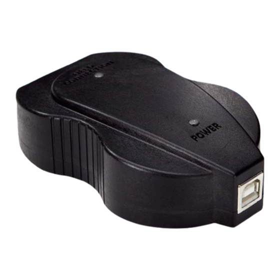
- Page 7 January 2019 User's Manual Parts and function Figure 2-2: USB Fieldbus Interface Field connection indicator light Indicates the fieldbus device connection status Power indicator light Indicates the power mode of the interface USB port Enables USB connection Fieldbus device connection socket Enables fieldbus device or segment connection See the Indicator light scenarios table.
- Page 8 Normal scenarios The USB Fieldbus Interface is connected to an externally Green Green powered segment and is able to communicate. The USB Fieldbus Interface is providing power to a fieldbus Amber Green segment and is able to communicate. Other scenarios The USB Fieldbus Interface is not connected to a powered computer.
- Page 9 In Mode 2, it can provide current of up to 85 mA (typically sufficient for three or four fieldbus devices on the same segment). You can configure Mode 2 using the USB Fieldbus Interface Configuration utility. For more information, see Section 4.3.
-
Page 10: Software Installation And Device Setup
Connect to a live fieldbus segment Perform software installation and device setup in the following order: 1. Install the USB Fieldbus Interface Configuration utility. This allows you to configure the USB Fieldbus Interface and connected fieldbus devices. 2. Install the Communication DTM software. - Page 11 Install the USB Fieldbus Interface Configuration utility Notes • Do not connect the USB Fieldbus Interface to the computer or to a fieldbus device or segment until software installation is complete. • You may be prompted to determine the operating system and the Windows version (32-bit or 64-bit) running on your computer.
- Page 12 Install the Emerson DTM Library 1. Insert the USB Fieldbus Interface installation CD/DVD. 2. Navigate to the Emerson DTM Library folder. The DTM library folder is typically named "Emerson Process Management FF Device DTM Library v1.x.x". 3. Double-click Setup > Setup.exe.
- Page 13 January 2019 User's Manual Figure 3-2: Emerson DTM Library installation 5. Click Close.
-
Page 14: Usb Fieldbus Interface Configuration
Install the USB Fieldbus Interface Configuration utility first before setting up and connecting the USB Fieldbus Interface. For more information, see Section 3.2 1. Connect the USB Fieldbus Interface to the computer using the USB cable provided. USB driver installation should start automatically. -
Page 15: Usb Fieldbus Interface Configuration
Configuration utility when connecting to a live segment. Doing so can disrupt communications and may compromise automation safety. 1. Make sure the USB Fieldbus Interface is connected to the computer and that all software and drivers are installed. 2. Plug one end of the field lead to the fieldbus device connection socket of the interface and connect the other end to the live fieldbus segment. - Page 16 USB Fieldbus interface act as the LAS. You can check the LAS address next to the segment info to find out which device is the LAS.
-
Page 17: Usb Fieldbus Interface Configuration Utility
Figure 4-1: No device detected dialog A connected fieldbus device or segment has to be powered by an external power source or by the USB Fieldbus Interface Configuration utility for it to be detected. For more information, see Section 7.2. - Page 18 User's Manual January 2019 1. Launch the USB Fieldbus Interface Configuration utility. 2. Click Start Server or Stop Server. Figure 4-2: Start Server/Stop Server Note The USB FF HSE Server should be running to use the USB Fieldbus Interface Configuration utility to power or configure a fieldbus device or...
- Page 19 2. Select the Supply Power check box. Note The USB Fieldbus Interface is only capable of providing an output current of up to 85 mA. Typically, you should not attempt to connect more than three or four fieldbus devices on the same segment when using the Supply Power option.
- Page 20 You need to commission fieldbus devices first before you can use them with AMS Device Manager or with an FDT Frame Application. • The USB Fieldbus Interface must be acting as the Link Master to commission or decommission. 1. Launch the USB Fieldbus Interface Configuration utility.
- Page 21 2. Double-click the Fieldbus device icon you want to configure. A device screen is displayed. Note A connected fieldbus device or segment should be powered by an external power source or by the USB Fieldbus Interface Configuration utility for it to be detected.
- Page 22 A Link Master contains the LAS functionality that controls communications on a fieldbus link or segment. 1. Launch the USB Fieldbus Interface Configuration utility. 2. Double-click the Fieldbus device icon you want to configure. A device screen is displayed.
- Page 23 Note A connected fieldbus device or segment should be powered by an external power source or by the USB Fieldbus Interface Configuration utility for it to be detected. 3. If Device Class is not displayed, click Read to identify if the fieldbus device is a Link Master or a basic device.
- Page 24 User's Manual January 2019 Figure 4-7: Change the device class 5. Click Yes to acknowledge the restart of the device. 6. Click OK to continue. The operation is complete when the Apply button is grayed out. Note Changing the device class takes about 1 minute to complete.
-
Page 25: Using With Ams Device Manager
Contact your Emerson Sales/Support representative for more information on AMS Device Manager. Add a network component in AMS Device Manager An FF HSE network component is required to use the USB Fieldbus Interface with AMS Device Manager. Notes •... - Page 26 User's Manual January 2019 Figure 5-1: Add a network component 3. Select the FF HSE Network component, and click Install.
- Page 27 January 2019 User's Manual Figure 5-2: Install an FF HSE network component 4. Click Next. 5. Enter a name for the FF HSE network, and click Next.
- Page 28 User's Manual January 2019 Figure 5-3: Enter a network name 6. Choose to automatically discover FF HSE linking devices or manually configure IP addresses for FF HSE linking devices.
- Page 29 Notes • Choosing the PC NIC address in the Primary HSE NIC Address field displays the USB Fieldbus Interface and any local FF HSE interfaces on the network in the AMS Device Manager hierarchy. • Choosing the localhost address (127.0.0.1) in the Primary HSE NIC Address field displays only the USB Fieldbus Interface in the AMS Device Manager hierarchy.
- Page 30 2. From the Device Connection or Device Explorer view, right-click the FF HSE network icon and select Rebuild Hierarchy. The USB Fieldbus Interface icon then appears under the FF HSE network. Figure 5-5: USB Fieldbus Interface icon in AMS Device Manager...
- Page 31 If you are using the Device Connection View, click the sign next to the USB Fieldbus Interface icon to display a list of connected fieldbus devices. 4. If necessary, right-click the USB Fieldbus Interface icon and then scan new devices. Scanning synchronizes the AMS Device Manager database with connected live devices.
- Page 32 User's Manual January 2019 Service Tools or Displays alert conditions. These include Device Diagnostics hardware and software malfunctions or parameters with values beyond the device specifications. Overview or Displays the current output from the device. Process Variables For more information about the context menus and other AMS Device Manager functions, refer to AMS Device Manager Books Online.
-
Page 33: Using With An Fdt Frame Application
PACTware can be downloaded from multiple sites on the Internet. Install an FDT Frame Application Note Install the Communication DTM software and the Emerson DTM Library first before installing an FDT Frame application. For instructions, see Section 3.3 Section 3.4. - Page 34 If necessary, update the DTM library. For more information, see Section 6.2. • Make sure the USB Fieldbus Interface and fieldbus devices are correctly set up and that the USB Fieldbus Interface Configuration utility is installed and running. For more information, see Section 3.5 Chapter 1. Launch PACTware.
- Page 35 Figure 6-2: Project pane Press F2 to display the Project pane if it is not already displayed. 3. Select Emerson FF HSE Server and click OK. Figure 6-3: Add the Emerson FF HSE Server 4. Right-click FF HSE Server on the Project pane and click Add device.
- Page 36 User's Manual January 2019 Figure 6-4: FF HSE Server - Add device 5. Select Emerson USB Fieldbus Interface and click OK.
- Page 37 January 2019 User's Manual Figure 6-5: Add the Emerson USB Fieldbus Interface 6. Right-click USB Fieldbus Interface on the Project pane and click Add device.
- Page 38 User's Manual January 2019 Figure 6-6: USB Fieldbus Interface - Add device 7. Select the device you want to add then click OK.
- Page 39 Only devices with DTMs available and installed appear on the list. For more information on DTM library installation, see Section 3.4. Repeat steps 6 and 7 if you want to add more devices to the list. 8. Right-click USB Fieldbus Interface and select Additional functions > Edit DTM Address.
- Page 40 User's Manual January 2019 Figure 6-8: Edit DTM Address 9. On the right pane, select the fieldbus device from the list, enter the device address in the Node ID field, and click Apply. Figure 6-9: Enter Node ID...
- Page 41 January 2019 User's Manual Note The device address and Node ID should match. The device address is set and can be found in the USB Fieldbus Interface Configuration utility. For more information on setting the device address, see Section 4.4.
- Page 42 User's Manual January 2019 Figure 6-11: Parameter This displays the various parameters you can edit for the device. 12. Configure the parameters of the device. Note The parameter display varies and is dependent on the device manufacturer.
- Page 43 January 2019 User's Manual Figure 6-12: Edit device parameters...
-
Page 44: Troubleshooting
Cannot edit device parameters in FDT Frame Application Fieldbus device not responding in AMS Device Manager To configure a fieldbus device in AMS Device Manager, you must first commission the device in the USB Fieldbus Interface Configuration utility. For more information on commissioning a device, see Section 4.4. - Page 45 Figure 7-2: Commissioned device in AMS Device Manager Fieldbus device not detected in USB Fieldbus Interface Configuration utility The USB Fieldbus Interface Configuration utility immediately detects connected fieldbus devices. If 35 seconds have elapsed and no device is...
- Page 46 No device detected dialog Click OK and check for the following: • Make sure the fieldbus device or segment is powered either by an external source or by the USB Fieldbus Interface. For more information, see Section 2.3. • Make sure drivers are installed and that the hardware is ready for use.
- Page 47 January 2019 User's Manual Cannot edit device parameters in FDT Frame Application Figure 7-4: Cannot edit device parameters in PACTware • Check the Node ID in PACTware and the Device Address in the USB Fieldbus Interface Configuration utility. The Node ID and Device Address should match.
-
Page 48: Approvals And Certifications
47 CFR, Part 15:2009, §15.107, §15.109, Class B Any modifications made to this device that are not approved by Emerson may void the authority granted to the user by the FCC to operate this equipment. -
Page 49: Specifications
January 2019 User's Manual Appendix B Specifications Software Windows 7 (32- or 64-bit) Supported operating systems Windows 10 USB 1.1 and USB 2.0 interface Drivers included Application software AMS Device Manager Version 11.5 or later License AMS Device Manager HSE license Part number AW7060HSE Electrical Power consumption (Mode 1) -
Page 50: Waste Disposal
Emerson sales representative for information on discarding any part of the USB Fieldbus Interface. For customers in all other world areas, if it is necessary to discard any part of the USB Fieldbus Interface, follow the waste disposal regulations applicable in your location. -
Page 51: Remove Pre-Release Driver Versions On A Windows 7 Or 10 Operating System
2. Expand Ports (COM & LPT). 3. Connect the USB Fieldbus Interface to the computer through the USB port and wait a few seconds to see if 770 Fieldbus Interface (COMxx) appears on the list. - Page 52 Communication DTM contents of box install Emerson DTM Library install FDT Frame Application install USB Fieldbus Interface Configuration utility decommission fieldbus devices device class, changing drivers automatic installation launch the utility...
- Page 53 USB FF HSE Server benchtop/segment connection starting, stopping live segment connection USB Fieldbus Interface Configuration utility system requirements installing launching starting/stopping HSE server manually troubleshooting cannot edit device parameters, PACTware...
- Page 54 All rights reserved. The Emerson logo is a trademark and service mark of Emerson Electric Co. All other marks are property of their respective...
Need help?
Do you have a question about the USB Fieldbus Interface and is the answer not in the manual?
Questions and answers