
Subscribe to Our Youtube Channel
Related Manuals for Emerson SPS 4001B


Summary of Contents for Emerson SPS 4001B
- Page 1 Instruction Manual IM-106-340AC-1, Rev 1.2 January 2007 SPS 4001B Single Probe Autocalibration Sequencer http://www.raihome.com...
- Page 3 HIGHLIGHTS OF CHANGES Effective January, 2007 Rev 1.2 Page Summary General Updated instances of Rosemount Analytical with Emerson Process Management throughout the book where appropriate. Page 1-3 Changed 20 psi (138) kPa to 25 psi (172 kPa). Page 1-5 Changed 20 psi (138) kPa to 25 psi (172 kPa).
-
Page 5: Table Of Contents
Overview ..........5-1 SPS 4001B Troubleshooting ....... 5-1... - Page 6 Instruction Manual IM-106-340AC-1, Rev. 1.2 SPS 4001B January 2007 TOC-2...
-
Page 7: Essential Instructions
ESSENTIAL READ THIS PAGE BEFORE PROCEEDING! INSTRUCTIONS Emerson Process Management designs, manufactures and tests its products to meet many national and international standards. Because these instruments are sophisticated technical products, you MUST properly install, use, and maintain them to ensure they continue to operate within their normal specifications. -
Page 8: Preface
January 2007 PREFACE The purpose of this manual is to provide information concerning the components, functions, installation and maintenance of the SPS 4001B Single Probe Autocalibration Sequencer. Some sections may describe equipment not used in your configuration. The user should become thoroughly familiar with the operation of this module before operating it. -
Page 9: Component Checklist
Figure 1-1. Record the part number, serial number, and CHECKLIST order number for the SPS 4001B on the back cover of this manual. NOTE The SPS 4001B operates exactly the same with either the Oxymitter 4000 Oxygen Transmitter or the Oxymitter 5000 Oxygen Transmitter with FOUNDATION fieldbus communications. -
Page 10: Overview
Oxymitter 4000 without sending a technician to the probe site. The SPS 4001B replaces the SPS 4000, a similar unit with exposed analog devices mounted to a stainless steel support bracket. The operating parameters of the SPS 4000 and SPS 4001B are identical. All SPS units require additional calibration system components. -
Page 11: Specifications
, such as when the probe is mounted into a positive pressure duct with leaks or where there is a process unit nearby with leaks. (3) Customer to provide piping from remote SPS 4001B to probe. (4) External current limiting device must be provided by customer. -
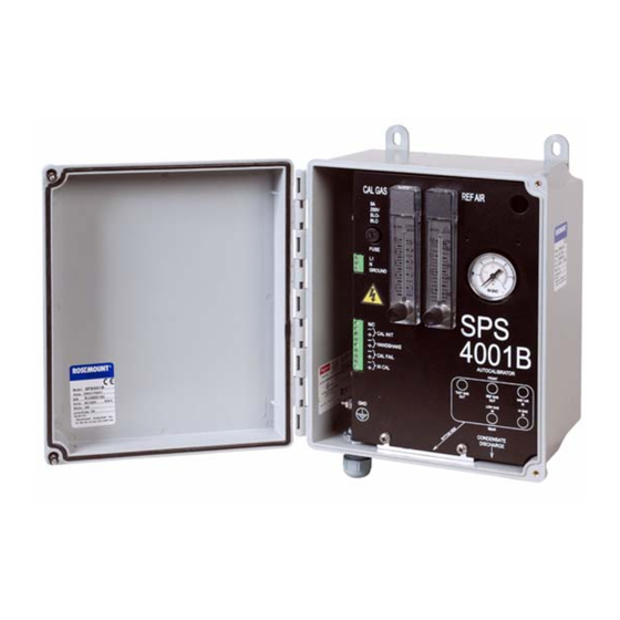
Page 12: Physical Description
(2) When the bottles are used with "CALIBRATION RECOMMENDED" features, the bottles should provide 2 to 3 years of calibrations in normal service. PHYSICAL The main components of the SPS 4001B are illustrated in Figure 1-2. DESCRIPTION Manifold The manifold provides porting to and from the calibration solenoids. The manifold ports are accessible from outside the enclosure for making piping connections. - Page 13 Instruction Manual IM-106-340AC-1, Rev. 1.2 SPS 4001B January 2007 Calibration Gas Solenoids The solenoids sequence the calibration gases. One solenoid controls calibration gas 1 (high calibration gas), and the other controls calibration gas 2 (low calibration gas). The solenoids activate and deactivate to allow the calibration gases to flow between the sequencer and Oxymitter 4000.
-
Page 14: Theory Of Operation
This feature automatically performs an impedance check every hour on the Oxymitter 4000. If a calibration is recommended and its contact output signal is set for "handshaking" with the SPS 4001B sequencer, the Oxymitter 4000 sends a signal to the sequencer. The sequencer automatically performs a calibration upon receiving the signal. - Page 15 Instruction Manual IM-106-340AC-1, Rev. 1.2 SPS 4001B January 2007 Figure 1-3. SPS 4001B Calibration Setup OXYMITTER 4000 NOTES: (BOTTOM VIEW) A CHECK VALVE IS REQUIRED AT THE OXYMITTER 4000 (BETWEEN THE CALIBRATION GAS FITTING AND THE GAS LINE) TO PREVENT THE MIGRATION...
- Page 16 Instruction Manual IM-106-340AC-1, Rev. 1.2 SPS 4001B January 2007...
-
Page 17: Overview
MECHANICAL The outline drawing in Figure 2-1 shows mounting centers and clearances of the SPS 4001B. The unit is designed to mount on a wall, bulkhead, or pipe. INSTALLATION Ensure the unit is installed according to the following specifications. -
Page 18: Gas Connections
Instruction Manual IM-106-340AC-1, Rev. 1.2 SPS 4001B January 2007 GAS CONNECTIONS Use the following procedures to connect the reference air and the calibration gases. Reference Air (Figure 2-1) Do not exceed maximum pressure for instrument air. Failure to limit pressure could result in equipment failure, serious injury or death. - Page 19 Instruction Manual IM-106-340AC-1, Rev. 1.2 SPS 4001B January 2007 Figure 2-1. Installation REPLACEABLE 5-15/16 MOUNTING FOOT (151) (4 PLACES) (279) Analytical CONDENSATE DISCHARGE TUBE (FROM AIR PRESSURE REGULATOR/FILTER) TEST GAS REF GAS INST AIR SIGNAL CABLE IN MANIFOLD 3/8 IN. (9,5 MM)
-
Page 20: Electrical Connections
To maintain proper earth grounding, ensure a positive connection exists between the ground lug and earth. Install this wire or ground lug first. 1. Loosen the SPS 4001B cover screws and open the cover. 2. Route the line voltage cable into the enclosure through the rear cable grip. - Page 21 4000 to the terminal strip as indicated in Figure 2-2. Use shielded twisted pair wiring. Terminate the shield at the Oxymitter 4000. 6. To set up the SPS 4001B to initiate a calibration from a remote location, connect the 5 VDC input leads to the terminal strip as shown in Figure 2-2.
- Page 22 Instruction Manual IM-106-340AC-1, Rev. 1.2 SPS 4001B January 2007 Figure 2-2. Electrical Connections 90 - 250 VAC, 50/60 HZ LINE VOLTAGE INPUT GROUND OPTIONAL 5 VDC (SELF-POWERED) TO REMOTE MOMENTARY CAL INIT CLOSURE CONTACT INPUT CONNECTION 5 VDC (5 mA MAXIMUM)
-
Page 23: Overview
Instruction Manual IM-106-340AC-1, Rev. 1.2 SPS 4001B January 2007 Section 3 Operation Overview ........page 3-1 Calibration Requirements . - Page 24 Instruction Manual IM-106-340AC-1, Rev. 1.2 SPS 4001B January 2007 In addition to the optional disposable gas bottles available from Emerson Process Management, two additional sources of calibrated gas mixtures are: LIQUID CARBONIC GAS CORP. SPECIALTY GAS LABORATORIES 700 South Alameda Street...
-
Page 25: Reference Air Flow Setup
Oxymitter 4000 to verify SPS 4001B operation and the communication link FLOW SETUP between the sequencer and Oxymitter 4000. 1. Verify that both calibration gases are connected to the SPS 4001B. Also verify that the pressure regulators on both calibration gas bottles are set to 25 psi (172 kPa). -
Page 26: Semi-Automatic Calibration
Instruction Manual IM-106-340AC-1, Rev. 1.2 SPS 4001B January 2007 SEMI-AUTOMATIC Semi-automatic calibrations are operator initiated and can be performed using the Oxymitter 4000 keypad, HART handheld communicator/AMS software, or CALIBRATION a remote contact. In addition, the calibration gases must be permanently piped to the Oxymitter 4000. -
Page 27: Overview
Cleaning ........page 4-7 OVERVIEW This section describes service and routine maintenance of the SPS 4001B. Replacement parts are available from Emerson Process Management. Refer to Section 6, Replacement Parts for part numbers and ordering information Secure equipment cover and ground leads after equipment service. -
Page 28: Fuse Replacement
SPS 4001B January 2007 FUSE REPLACEMENT The SPS 4001B has a fuse on the circuit board. Refer to Section 6, Replacement Parts for replacement fuse specifications. Perform the following procedure to check or replace the fuse Dosconnect and lock out power before working on any electrical components. - Page 29 Instruction Manual IM-106-340AC-1, Rev. 1.2 SPS 4001B January 2007 Figure 4-1. SPS 4001B, Exploded View Lo Cal Gas Hi Cal Gas 1. Screw 8. Screw 15. Low Cal. Gas Solenoid 22. Reference Air Pressure 2. Fuse 9. Adapter Fitting 16. Pressure Switch Regulator 3.
-
Page 30: Remove/Install Chassis
Removal 1. Loosen the SPS 4001B cover screws and open the cover. 2. Shut off the calibration gas and reference air to the SPS 4001B. Disconnect all pneumatic lines at the SPS 4001B manifold. 3. Refer to Figure 2-2. Disconnect all wires from the chassis terminals and remove the power cable ground lead from the ground lug. - Page 31 Instruction Manual IM-106-340AC-1, Rev. 1.2 SPS 4001B January 2007 Figure 4-2. Terminal Connections 90 - 250 VAC, 50/60 HZ LINE VOLTAGE INPUT GROUND OPTIONAL 5 VDC (SELF-POWERED) TO REMOTE MOMENTARY CAL INIT CLOSURE CONTACT INPUT CONNECTION 5 VDC (5 mA MAXIMUM)
-
Page 32: Circuit Board Replacement
Perform the following procedure to replace circuit board (5, Figure 4-1). REPLACEMENT Disconnect and lock out power before working on any electrical components. 1. Remove the SPS 4001B chassis from the enclosure according to the instructions in "Remove/Install Chassis". 2. Refer to Figure 4-2. Disconnect wiring from the circuit board. -
Page 33: Pressure Switch Replacement
PRESSURE SWITCH Use the following procedure to replace pressure switch (16, Figure 4-1). REPLACEMENT 1. Remove the SPS 4001B chassis from the enclosure according to the instructions in "Remove/Install Chassis". 2. Remove lead wire terminals from pressure switch (16). 3. Use a 1-1/16 in. 6-point socket to loosen and remove switch (16). - Page 34 Instruction Manual IM-106-340AC-1, Rev. 1.2 SPS 4001B January 2007...
-
Page 35: Overview
Overview ........page 5-1 SPS 4001B Troubleshooting ..... . . page 5-1 OVERVIEW This section describes the SPS 4001B troubleshooting procedures. -
Page 36: Sps 4001B
2. Perform another calibration and monitor the process. If the calibration fails before both calibration gases finish sequencing, a gas flow problem exists. Refer to Table 5-1 or Figure 5-1 to troubleshoot the SPS 4001B. If the calibration setup is correct and the Oxymitter 4000 indicates an... - Page 37 Instruction Manual IM-106-340AC-1, Rev. 1.2 SPS 4001B January 2007 Figure 5-1. SPS 4001B Troubleshooting Flowchart (Sheet 1 of 2) SYMPTOM — NO CALIBRATION GAS FLOW CHECK ALL WIRING BETWEEN OXYMITTER 4000 AND SPS 4001B WIRING PROPERLY CONNECT WIRING PROPERLY OR SECURE LOOSE WIRING CONNECTED CONNECTIONS;...
- Page 38 Instruction Manual IM-106-340AC-1, Rev. 1.2 SPS 4001B January 2007 Figure 5-1. SPS 4001B Troubleshooting Flowchart (Sheet 2 of 2) SYMPTOM — NO CALIBRATION GAS FLOW (CONTINUED) CONTINUED FROM SHEET 1 OF 2 NOTE 1: +5 VDC IS ON TP2; TP3 IS RETURN.
- Page 39 SPS 4001B ........
- Page 40 Instruction Manual IM-106-340AC-1, Rev. 1.2 SPS 4001B January 2007 SPS 4001B Figure 6-1. Replacement Parts Lo Cal Gas Hi Cal Gas...
-
Page 41: Calibration Components
Instruction Manual IM-106-340AC-1, Rev. 1.2 SPS 4001B January 2007 Index No. Part Number Description 771B635H02 Flow Meter Assembly, Reference Air 771B635H01 Flow Meter Assembly, Calibration Gas 1A98808H03 Fitting, 90 Degree, Nylon, 1/8 NPT 1A97913H22 Fuse, 1.6A, 260V, 5 x 20 mm, Fast Acting... - Page 42 Instruction Manual IM-106-340AC-1, Rev. 1.2 SPS 4001B January 2007...
- Page 43 Instruction Manual IM-106-340AC-1, Rev. 1.2 SPS 4001B January 2007 Appendix A Safety Data Safety Instructions ........page A-2...
-
Page 44: Safety Instructions
Instruction Manual IM-106-340AC-1, Rev. 1.2 SPS 4001B January 2007 IMPORTANT SAFETY INSTRUCTIONS SAFETY INSTRUCTIONS FOR THE WIRING AND INSTALLATION OF THIS APPARATUS The following safety instructions apply specifically to all EU member states. They should be strictly adhered to in order to assure compliance with the Low Voltage Directive. - Page 45 Instruction Manual IM-106-340AC-1, Rev. 1.2 SPS 4001B January 2007 DŮLEŽITÉ Bezpečnostní pokyny pro zapojení a instalaci zařízení Následující bezpečnostní pokyny se speciálně vztahují na všechny členské státy EU. Pokyny by měly být přísně dodržovány, aby se zajistilo splnění Směrnice o nízkém napětí. Pokud nejsou pokyny nahrazeny místními či národními normami, měly by je dodržovat i...
- Page 46 Instruction Manual IM-106-340AC-1, Rev. 1.2 SPS 4001B January 2007 VIGTIGT Sikkerhedsinstruktion for tilslutning og installering af dette udstyr. Følgende sikkerhedsinstruktioner gælder specifikt i alle EU-medlemslande. Instruktionerne skal nøje følges for overholdelse af Lavsspændingsdirektivet og bør også følges i ikke EU-lande medmindre andet er specificeret af lokale eller nationale standarder.
- Page 47 Instruction Manual IM-106-340AC-1, Rev. 1.2 SPS 4001B January 2007 BELANGRIJK Veiligheidsvoorschriften voor de aansluiting en installatie van dit toestel. De hierna volgende veiligheidsvoorschriften zijn vooral bedoeld voor de EU lidstaten. Hier moet aan gehouden worden om de onderworpenheid aan de Laag Spannings Richtlijn (Low Voltage Directive) te verzekeren.
- Page 48 Instruction Manual IM-106-340AC-1, Rev. 1.2 SPS 4001B January 2007 BELANGRIJK Veiligheidsinstructies voor de bedrading en installatie van dit apparaat. Voor alle EU lidstaten zijn de volgende veiligheidsinstructies van toepassing. Om aan de geldende richtlijnen voor laagspanning te voldoen dient men zich hieraan strikt te houden. Ook niet EU lidstaten dienen zich aan het volgende te houden, tenzij de lokale wetgeving anders voorschrijft.
- Page 49 Instruction Manual IM-106-340AC-1, Rev. 1.2 SPS 4001B January 2007 WICHTIG Sicherheitshinweise für den Anschluß und die Installation dieser Geräte. Die folgenden Sicherheitshinweise sind in allen Mitgliederstaaten der europäischen Gemeinschaft gültig. Sie müssen strickt eingehalten werden, um der Niederspannungsrichtlinie zu genügen.
- Page 50 Instruction Manual IM-106-340AC-1, Rev. 1.2 SPS 4001B January 2007 ΣΗΜΑΝΤΙΚΟ Οδηγιεσ ασφαλειασ για την καλωδιωση και εγκατασταση τησ συσκευησ Οι ακόλουθες οδηγίες ασφαλείας εφαρµόζονται ειδικά για όλες τις χώρες µέλη της Ευρωπαϊκής Κοινότητας. Θα πρέπει να ακολουθούνται αυστηρά ώστε να εξασφαλιστεί η συµβατότητα µε τις οδηγίες για τη Χαµηλή Τάση.
- Page 51 Instruction Manual IM-106-340AC-1, Rev. 1.2 SPS 4001B January 2007 OLULINE TEAVE Juhtmestiku ja seadme paigaldamisega seotud ohutusjuhised Alljärgnevad ohutusjuhised rakenduvad eriti kõigi Euroopa Liidu liikmesriikide suhtes. Antud juhiseid tuleb täpselt järgida, et kindlustada vastavus madalpinge direktiiviga. Euroopa Liitu mittekuuluvad riigid peavad samuti alljärgnevaid juhiseid järgima, va juhul, kui on olemas...
- Page 52 Instruction Manual IM-106-340AC-1, Rev. 1.2 SPS 4001B January 2007 TÄRKEÄÄ Turvallisuusohje, jota on noudatettava tämän laitteen asentamisessa ja kaapeloinnissa. Seuraavat ohjeet pätevät erityisesti EU:n jäsenvaltioissa. Niitä täytyy ehdottomasti noudattaa jotta täytettäisiin EU:n matalajännitedirektiivin (Low Voltage Directive) yhteensopivuus. Myös EU:hun kuulumattomien valtioiden tulee nou-dattaa tätä...
- Page 53 Instruction Manual IM-106-340AC-1, Rev. 1.2 SPS 4001B January 2007 IMPORTANT Consignes de sécurité concernant le raccordement et l'installation de cet appareil. Les consignes de sécurité ci-dessous s'adressent particulièrement à tous les états membres de la communauté européenne. Elles doivent être strictement appliquées afin de satisfaire aux directives concernant la basse tension.
- Page 54 Instruction Manual IM-106-340AC-1, Rev. 1.2 SPS 4001B January 2007 FONTOS Biztonsági előírások a készülék vezetékeléséhez és üzembeállításához A következő biztonsági előírások kifejezetten vonatkoznak az összes EU-tagállamra. Ezeket szigorúan be kell tartani a Kisfeszültségű irányelvnek való megfelelés biztosításához. A nem EU-tagállamok szintén tartsák be a következőket, kivéve ha a helyi és nemzeti...
- Page 55 Instruction Manual IM-106-340AC-1, Rev. 1.2 SPS 4001B January 2007 IMPORTANTE Norme di sicurezza per il cablaggio e l'installazione dello strumento. Le seguenti norme di sicurezza si applicano specificatamente agli stati membri dell'Unione Europea, la cui stretta osservanza è richiesta per garantire conformità...
- Page 56 Instruction Manual IM-106-340AC-1, Rev. 1.2 SPS 4001B January 2007 SVARBU š io prietaiso laidų prijungimo ir instaliacijos saugos instrukcijos Toliau išvardinti saugumo reikalavimai taikomi konkrečiai visoms ES šalims narėms. Jų turi būti griežtai paisoma, kad būtų užtikrintai laikomasi Žemos įtampos direktyvos. Ne ES narės taip pat turi laikytis toliau pateikiamų...
- Page 57 Instruction Manual IM-106-340AC-1, Rev. 1.2 SPS 4001B January 2007 SVARĪGI Droš ības norādījumi š īs iekārtas pievienoš anai un uzstādīš anai Turpmākie drošības norādījumi attiecas uz visām ES dalībvalstīm. Tie ir stingri jāievēro, lai nodrošinātu atbilstību Zemsprieguma direktīvai. Turpmāk norādītais jāievēro arī valstīs, kas nav ES dalībvalstis, ja vien šos norādījumus neaizstāj vietējie vai valsts standarti.
- Page 58 Instruction Manual IM-106-340AC-1, Rev. 1.2 SPS 4001B January 2007 IMPORTANTI STRUZZJONIJIET TAS-SIGURTÀ GĦALL-WIRING U L-INSTALLAZZJONI TAT-TAGĦMIR L-istruzzjonijiet tas-sigurtà japplikaw speċifikament għall-Istati Membri ta' l-UE. Dawn għandhom jiġu osservati b'mod strett biex tkun żgurata l- konformità mad-Direttiva dwar il-Vultaġġ Baxx. Stati li mhumiex membri ta' l-UE għandhom ukoll ikunu konformi ma' dan li ġej ħlief jekk dawn ikunu...
- Page 59 Instruction Manual IM-106-340AC-1, Rev. 1.2 SPS 4001B January 2007 VIKTIG Sikkerhetsinstruks for tilkobling og installasjon av dette utstyret. Følgende sikkerhetsinstruksjoner gjelder spesifikt alle EU medlemsland og land med i EØS-avtalen. Instruksjonene skal følges nøye slik at installasjonen blir i henhold til lavspenningsdirektivet. Den bør også...
- Page 60 Instruction Manual IM-106-340AC-1, Rev. 1.2 SPS 4001B January 2007 WAŻNE! Zalecenia dotyczące bezpieczeństwa w zakresie podłączania i instalacji tego urządzenia Następujące zalecenia dotyczą zwłaszcza stosowania urządzenia we wszystkich krajach Unii Europejskiej. Należy się ściśle do nich stosować w celu zapewnienia zgodności z dyrektywą niskonapięciową.
- Page 61 Instruction Manual IM-106-340AC-1, Rev. 1.2 SPS 4001B January 2007 IMPORTANTE Instruções de segurança para ligação e instalação deste aparelho. As seguintes instruções de segurança aplicam-se especificamente a todos os estados membros da UE. Devem ser observadas rigidamente por forma a garantir o cumprimento da Directiva sobre Baixa Tensão.
- Page 62 Instruction Manual IM-106-340AC-1, Rev. 1.2 SPS 4001B January 2007 DÔLEŽITÉ Bezpečnostné pokyny pre zapojenie káblov a inš taláciu tohto prístroja Nasledovné bezpečnostné pokyny sa vzt’ahujú konkrétne na všetky členské štáty EÚ. Musia byt’ striktne dodržané, aby sa zaistila zhoda so Smernicou o nízkom napätí.
- Page 63 Instruction Manual IM-106-340AC-1, Rev. 1.2 SPS 4001B January 2007 POMEMBNO Varnostna navodila za povezavo in vgradnjo naprave Naslednja varnostna navodila veljajo za vse države članice EU. Zaradi zagotovitve skladnosti z nizkonapetostno direktivo morate navodila strogo upoštevati. V državah, ki niso članice EU, je treba upoštevati tudi naslednje smernice, razen če jih ne zamenjujejo lokalni ali nacionalnimi...
- Page 64 Instruction Manual IM-106-340AC-1, Rev. 1.2 SPS 4001B January 2007 IMPORTANTE Instrucciones de seguridad para el montaje y cableado de este aparato. Las siguientes instrucciones de seguridad, son de aplicacion especifica a todos los miembros de la UE y se adjuntaran para cumplir la normativa europea de baja tension.
- Page 65 Instruction Manual IM-106-340AC-1, Rev. 1.2 SPS 4001B January 2007 VIKTIGT Säkerhetsföreskrifter för kablage och installation av denna apparat. Följande säkerhetsföreskrifter är tillämpliga för samtliga EU-medlemsländer. De skall följas i varje avseende för att överensstämma med Lågspännings direktivet. Icke EU medlemsländer skall också...
- Page 66 Instruction Manual IM-106-340AC-1, Rev. 1.2 SPS 4001B January 2007 A-24...
-
Page 67: Returning Material
If failure was due to conditions listed in the standard Rosemount Analytical warranty, the defective unit will be repaired or replaced at Emerson Process Management’s option, and an operating unit will be returned to the customer in accordance with shipping instructions furnished in the cover letter. - Page 68 Instruction Manual IM-106-340AC-1, Rev. 1.2 SPS 4001B January 2007...
- Page 69 Handshake ....2-4 SPS 4001B Package ..1-1 Handshake Mode ... 3-3...
- Page 70 Instruction Manual IM-106-340AC-1, Rev. 1.2 SPS 4001B January 2007 Index-2...
- Page 71 WARRANTY Rosemount Analytical warrants that the equipment manufactured and sold by it will, upon shipment, be free of defects in workmanship or material. Should any failure to conform to this warranty become apparent during a period of one year after the date of shipment, Rosemount Analytical shall, upon prompt written notice from the purchaser, correct such nonconformity by repair or replacement, F.O.B.
- Page 72 Republic of Singapore England T 713 467 6000 T 65 6 777 8211 T 44 1243 863121 F 713 827 3329 F 65 6 777 0947 F 44 1243 845354 E analytical@ ap.emersonprocess.com http://www.raihome.com © 2007 Emerson Process Management. All rights reserved.
Need help?
Do you have a question about the SPS 4001B and is the answer not in the manual?
Questions and answers