Blackmagicdesign Videohub Installation And Operation Manual
Hide thumbs
Also See for Videohub:
- Installation and operation manual (119 pages) ,
- Installation and operation manual (24 pages) ,
- Installation and operation manual (87 pages)
Table of Contents
Advertisement
Advertisement
Table of Contents

Related Manuals for Blackmagicdesign Videohub


Summary of Contents for Blackmagicdesign Videohub
- Page 1 Installation and Operation Manual Videohub April 2017...
- Page 2 HD-SDI routing. Videohub changes all that! Some Videohub models not only give you HD-SDI, but also the latest Ultra HD format, even enabling you to pipe 4K film around your studio just like video.
-
Page 3: Table Of Contents
Videohub 288 Crosspoint Card Connecting Videohub to a Network Universal Videohub Status LED’s Connect to an Ethernet Network Installing Interface cards Connect to a Videohub Server with USB Installing a Universal Configuring your Videohub Videohub Power Supply Server Settings Installing a second Power... - Page 4 Internal Software Saving and Loading Labels Blackmagic Videohub Control with Telnet in Windows Serial Control Settings Help Touchscreen Computers Replacing a fan in Universal Videohub Apple iPad Replacing the fan in Installing the Videohub Broadcast Videohub Software on iPad Regulatory Notices Videohub Hardware Panel Setup and Safety Information...
-
Page 5: Getting Started
Creating an IP Videohub with Teranex Mini IP Video 12G If you are looking for information on the creation of an IP Videohub for routing Blackmagic Teranex Mini IP Video 12G units, refer to the Teranex Mini IP Video 12G manual which can be downloaded from www.blackmagicdesign.com/support. -
Page 6: Blackmagic Videohub Software
If you cannot guarantee perfectly timed source signals but you still need to clean switch, then you can use Smart Videohub CleanSwitch 12x12 as this model features resynchronization on all inputs so you get perfect clean feeds. -
Page 7: Connect To A Videohub Server With Usb
IP address, despite having two Ethernet connections to the network switch. For Smart Videohub models with a built in control panel, you can use the rotary knob and buttons to configure IP address and network settings, or use Blackmagic Videohub Setup. For models without a front control panel, set your network settings using Blackmagic Videohub Setup. -
Page 8: Configuring Your Videohub Server Settings
Configuring your Videohub Server Settings If you will be using Ethernet to connect to your Videohub, refer to the “Blackmagic Videohub Setup” section in this manual. Videohubs without Ethernet are connected to a computer via USB and other control panels can see the Videohub by looking for this computer. -
Page 9: Configuring Network Settings With A Built In Control Panel
IP address” to provide a static IP address. Configuring Network Settings with a Built In Control Panel You can use Smart Videohub models’ built in control panel and LCD to configure network settings. Your router will be visible to other computers and hardware panels and these devices can then control the unit remotely and make the routing changes. -
Page 10: Smart Videohub Control Panel
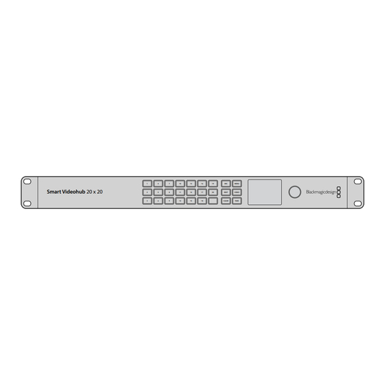
Smart Videohub routers include Blackmagic Smart Videohub 12x12, 20x20 and 40x40, plus Smart Videohub CleanSwitch 12x12. These models feature a built in control panel and LCD. Routing changes can be made without a computer by pressing the numbered pushbuttons on the front control panel. -
Page 11: Switching Routes With Smart Videohub
‘use take’ setting. Press the ‘take’ button to confirm the selection. Using the rotary knob, select ‘on’. This sets your Videohub to use the take button to confirm routing changes. To select cut bus mode, select ‘off’. This means when you select a source, it will be immediately routed without needing confirmation via the take button. -
Page 12: Videohub Hardware Control Panels
Introducing Videohub Hardware Control Panels Videohub Master Control Videohub Master Control is a 1 rack unit mountable control panel with 30 backlit pushbuttons, LCD, scroll wheel and Ethernet connectivity designed to perform Videohub crosspoint switching without using a computer. Videohub Master Control can control all sources and destinations for any size of Videohub router, as well as RS-422 deck control. -
Page 13: Connecting Usb To Configure The Control Panel
A USB 2.0 connection to a computer is used to configure the network settings of the Videohub Controller. Be aware that the USB port of the Videohub Smart Control is inaccessible once it is installed in a rack. If you are likely to reconfigure Videohub Smart Control network settings periodically, then it may be convenient to permanently connect a USB cable to the unit before installing Videohub Smart Control in a rack. -
Page 14: Control Panel Button Diagnostics
20x20 via an Ethernet Network Switch. Control Panel Button Diagnostics When power is first connected to a Videohub control panel, all the buttons will display their test lights in the following sequence: red, green, blue and white. The top left button of a Videohub control panel indicates its network status, using the following diagnostic display: Pink flashing light - unit is attempting to acquire an IP address. -
Page 15: Updating The Software In Your Videohub Controller
DHCP server has spare IP addresses available. Unplug and reconnect all power sources from the Videohub control panel so it will request a new IP address from the DHCP server. The button should quickly become red. The unit will only perform these diagnostics when it is not selected in Videohub Hardware Panel Setup software. -
Page 16: About Routing Levels
“SDI” on its LCD and you don’t need to read anything more about routing levels. If your Videohub does include RS-422 remote deck control ports, you can use the LEVEL button on Videohub Master Control to reduce the list of sources and destinations by routing level. -
Page 17: How To Select Sources And Destinations
How to select devices by typing the Videohub port numbers If you’ve chosen to keep the default labels for all Videohub SDI and remote ports, you can simply type the port numbers to make a routing change. This method is fast but requires that you remember port numbers or have devised a system for knowing what equipment is connected to each Videohub port. - Page 18 How to select devices with the scroll wheel Regardless of whether or not you’ve customized the Videohub port labels, you can always use the scroll wheel to browse through a list of sources and destinations. This is the slowest method but is useful if you want to see the list of all available equipment and ports.
- Page 19 The TAKE button will flash red, awaiting your confirmation of the route change. Press TAKE and the route will change immediately. Otherwise, press CLEAR and no route change will take place. Videohub Master Control will then return to its idle state with the latest route displayed on the LCD.
- Page 20 The TAKE button will flash red, awaiting your confirmation of the route change. Press TAKE and the route will change immediately. Otherwise, press CLEAR and no route change will take place. Videohub Master Control will then return to its idle state with the latest route displayed on the LCD.
- Page 21 The TAKE button will flash red, awaiting your confirmation of the route change. Press TAKE and the route will change immediately. Otherwise, press CLEAR and no route change will take place. Videohub Master Control will then return to its idle state with the latest route displayed on the LCD.
-
Page 22: Using Videohub Smart Control As A Cut-Bus Controller
Press and hold the gold DEST button until a lock icon appears in the destination field of the LCD. Press DEST again to return Videohub Master Control to its idle state and the destination field will revert to gray. Source... -
Page 23: Using Videohub Smart Control As An Xy Controller
Take button. Using Videohub Smart Control as an XY Controller If Videohub Smart Control has been configured as an XY controller, destination buttons light up gold and source buttons light up white. When working with multiple destinations, always select a destination button before selecting a source button. -
Page 24: Labeling Pushbuttons
Gently lift the face plate off the unit. If you have a Videohub Master Control, take care not to pull on the data cable that connects the scroll wheel to the rest of the unit. -
Page 25: Universal Videohub Routers
8 screws, lift off the face plate and then the button caps. For Videohub Master Control, remove the 8 screws, lift off the face plate and carefully allow the face plate to lie down next to the rest of the unit. Then remove the button caps. -
Page 26: Crosspoint Card
Occasionally, the internal software of the Universal Videohub 288 will need to be updated. Videohub Setup will prompt you if an update is required. The utility uses the USB 2.0 connection and you will need to provide a USB 2.0 type A to mini B male cable. -
Page 27: Router Control Cable
25 rack units of space should be reserved for the installation of Universal Videohub 288 and two rack mount power supply chassis, allowing free space for heat dissipation. Only 23 RU is required if Universal Videohub 288 is mounted at the top of an open rack as heat can be dissipated from the top. -
Page 28: Installing A Universal Videohub 288 Crosspoint Card
Installing a Universal Videohub 288 Crosspoint Card Now that your Universal Videohub 288 has been mounted in a rack, it needs to be fitted with a crosspoint card. The crosspoint card is the brains of Universal Videohub and performs video route and deck control switching. -
Page 29: Universal Videohub Status Led's
Universal Videohub Status LED’s The status LED’s marked ‘alarm’, ‘power overload’ and ‘ref in’ provide you with an indication of the current state of the Blackmagic Universal Videohub 288 Crosspoint. The following LED conditions provide specific information about the status of the unit. -
Page 30: Installing Interface Cards
Universal Videohub. Installing a Universal Videohub Power Supply The Universal Videohub Power Supply package consists of a power card, a power cable and a 1 RU chassis containing the power supply. A second Universal Videohub Power Supply can be installed under the first power supply for failover redundancy. You will need to provide a standard IEC cord with a C13 connector for each power supply. - Page 31 This power supply should only be considered if attempting to minimize the cost of purchasing a Universal Videohub 288. A second Universal Videohub 450W Power Card with three power bricks can be connected to the Universal Videohub 288 to ensure continued operation should the first power card fail.
-
Page 32: Installing A Second Power Supply While Universal Videohub 288 Is Running
Connect an IEC cord from each new power supply to the wall socket and turn on the power. If you need to remove or replace a power brick while Universal Videohub 288 is still running from a second power card and set of power supplies, power off the brick while being careful to avoid switching off power to the remaining power supplies. -
Page 33: Removing A Power Supply While Universal Videohub 288 Is Running
Universal Videohub 288. When using a Universal Videohub 72 Crosspoint card, only the bottom row of 18 interface cards can be used. A Universal Videohub 288 Crosspoint card must be used if you want to install more than 18 interface cards. - Page 34 The additional supporting bridge, short blanking plate and associated screws are available as a separate package from your Videohub dealer. Torx T8, Torx T10, number 01 and number 02 size Pozidriv screwdrivers are required to install the additional supporting bridge and the Universal Videohub 72 Crosspoint card.
-
Page 35: Universal Videohub 72
To install the Universal Videohub 72 Crosspoint card, hold the card in a vertical orientation by its two levers. The BNC, Ethernet and other ports should be towards the bottom end of the card. Gently insert the unit into its slot, below the additional supporting bridge, and ensure the top and bottom edges of the card follow the black guides. -
Page 36: Crosspoint Card
USB 2.0 type A to mini B male cable. Universal Videohub 72 ships as an empty rack frame, except for a removable fan tray and fans. All other hardware components, including SDI interface cards, deck control cables, crosspoint card and power supplies must be purchased and installed separately. -
Page 37: Building Videohub 72
Installing a Universal 72 Crosspoint Card Now that your Universal Videohub 72 has been mounted in a rack, it needs to be fitted with a crosspoint card. The crosspoint card is the brains of any Universal Videohub and performs video route and deck control switching. -
Page 38: Universal Videohub Status Led's
Universal Videohub Status LED’s The status LED’s marked ‘alarm’, ‘power overload’ and ‘ref in’ provide you with an indication of the current state of the Blackmagic Universal Videohub 72 Crosspoint. The following LED conditions provide specific information about the status of the unit. -
Page 39: Installing Interface Cards
If you have only partially populated your Universal Videohub 72 with interface cards, you might be able to power it with a single 150W power supply and preferably use a second power supply for failover redundancy. -
Page 40: Sdi Interface Card
If you need to remove or replace a 150W Power Supply while Universal Videohub 72 is still running, power off the brick while being careful to avoid switching off power to the remaining power supplies. -
Page 41: Universal Videohub Interface Cards
Universal Videohub Deck Control Cable Universal Videohub Interface Cards Universal Videohub SDI Interface Universal Videohub Optical Interface Activity light Activity light MAIN POWER MAIN POWER MAIN P +12V 800W +12V +12V Output 1 Output 1 Input 1 Output 2 Output 3... -
Page 42: 3G-Sdi Videohub Routers
However the Videohub Server computer must remain powered at all times so that Videohub settings can be modified. You will need to provide a standard USB 2.0 type A-B male cable to connect Broadcast Videohub to the server computer. -
Page 43: Using The Smart Videohub Control Panel
Blackmagic Smart Videohub Using the Smart Videohub Control Panel Smart Videohub features a built in 32 pushbutton control panel on the front of the router. Routing changes can be made without needing a computer as there is a pushbutton for each SDI input and output on Smart Videohub. -
Page 44: Videohub Router Monitoring
The illuminated pushbuttons display the last route made with the Smart Videohub control panel. However, if you select the same destination pushbutton as another remote user and they change the source to that destination, you will see the change reflected on your Smart Videohub. -
Page 45: Using The Built In Control Panel And Lcd
LCD will be active. Press a numbered button on the control panel to select your desired view, or alternatively you can use the rotary knob to scroll through the views. Confirm your setting by pressing the ‘set’ button. Videohub Router Monitoring... - Page 46 MENU SD/HD/3G/6G-SDI IN HDMI OUT 6G-SDI OUT HD-SDI OUT MENU SOLO VIEW MENU Press the ‘solo’ button to enter fullscreen mode. Press the ‘menu’ button to enter the settings page and to return to the home screen. Videohub Router Monitoring...
-
Page 47: Blackmagic Videohub Software
Blackmagic Videohub Software To install your Blackmagic Videohub software Videohub software runs on the latest El Capitan version of Mac OS X. It also runs on the 32 and 64 bit versions of Windows 10. Windows installation Double click the installer file from the supplied media or from your downloads folder if you downloaded the software from the Blackmagic Design website. -
Page 48: Network Settings
Blackmagic Videohub Setup is also used to enter labels. Note that port labels on an IP Videohub cannot be edited through this utility, as these labels come from the connected IP Video devices. The labels are stored on the connected Videohub and are also visible on the other control panels connected to your network. - Page 49 Automatic port direction simplifies configuration and works well with most editing systems. However, if you need to make instant port direction changes, you can set the port direction manually. Non-Roman character sets can also be used with the Smart Videohub family. Customize Input Labels...
-
Page 50: Naming Your Videohub
Naming your Videohub Give your Videohub a unique name to make it easy to identify when controlling it over a network. Click on the ‘configure’ tab and then click in the ‘name’ text field. Enter your Videohub’s name and use things such as location or owner to make it easy for users to recognize and then click the ‘save’... - Page 51 Launch Videohub Control and click on Settings (the gear icon) and choose ‘select Videohub’. Click on the Videohub that you wish to control. If you have customized your labels, the names you assigned will appear within the software. All Videohubs on the network, including IP Videohubs, will appear in this list.
- Page 52 The tape deck button is no longer illuminated and is disconnected from the video monitor. Refer to the ‘controlling videohub with software’ section for more information on using Videohub Control. Resizing the Interface Click and drag the bottom right hand corner to proportionally resize the interface to best fit your screen size.
- Page 53 Pushbutton View denote paired connections Click and drag the window edges to resize Blackmagic Videohub Control to fit your screen size. Drag the Divider Bar up or down to reveal more or less of the “Sources” and “Destinations” areas and use the Scroll Bars to scroll the areas.
- Page 54 The Set Button window appears and allows you to set the SDI source or destination, RS-422 deck control and the icon for the pushbutton. In most cases, deck control is grouped with the associated SDI connections. eg: SDI Input 1 would be associated with the corresponding Remote 1. Blackmagic Videohub Software...
- Page 55 Once enabled, any attempt to change a video route using a pushbutton will cause a red “TAKE” button to appear. Select the button to confirm or click the current source or destination pushbutton to cancel. Blackmagic Videohub Software...
- Page 56 The video destination devices will not be available to you until the destination pushbuttons have been unlocked from the other users’ computers and iPads. If you need to unlock a route set by another user, launch Videohub Setup, select the Outputs tab and click the destination’s lock icon.
-
Page 57: Serial Control Settings
Third party router controllers can control Videohub with RS-422 serial connections. If controlling Videohub via RS-422, set the “Leitch protocol” switch to: ‚ “Leitch Client” if the Videohub is to act as a client of a connected control panel and to listen and respond to the control panel button presses. -
Page 58: Apple Ipad
‘installing the Videohub Software on iPad’ immediately after this section. Up to 40 sources and 8 destinations can be displayed in a single Videohub Pushbutton screen on the iPad. Even more sources and destinations can be displayed by flicking the iPad left or right, or tapping to the left or right of the row of dots, to move through multiple Pushbutton screens. - Page 59 The initial Pushbutton interface Upon launching the Videohub app on your iPad for the first time, all pushbuttons initially show the generic BNC connector icon, which you can then replace from a selection of icons. If the connections have not yet been labeled, then the source pushbuttons will appear as Input 1 to Input 40 and the destination pushbuttons will appear as Output 1 to Output 8.
- Page 60 This is to avoid other users accidentally seizing the deck control belonging to the video source. The RS-422 connection between the video source and video destination will remain locked until the destination pushbutton is unlocked. Blackmagic Videohub Software...
-
Page 61: Installing The Videohub Software On Ipad
If you encounter a gray padlock icon and do not know who locked the video device you can override the lock using the Videohub software on a Mac OS X or Windows computer. When a route is unlocked, the padlock icon will disappear. -
Page 62: Videohub Hardware Panel Setup
Videohub Control Panels pane next to an Ethernet network icon. If several Videohub control panels are listed, but you don’t know which one is which, select one of them and then press Identify. This will cause all the buttons of the selected Videohub control panel to flash white. - Page 63 IP address if you are connecting directly to an Ethernet-equipped Videohub, such as Compact Videohub, without using a network switch. You will also need to complete the IP details for the remote Videohub that you wish to control with your Videohub control panel. The remote Videohub is the Videohub Server. This could refer to a Videohub Server computer or an integrated Videohub Server onboard a Videohub model such as Universal Videohub 72.
-
Page 64: Master Control
Add Videohub Control If you already know the IP address of a Videohub control panel but it hasn’t automatically appeared in the Videohub Control Panels pane, you can add the unit manually. Press the + (add device) button at the bottom of the Videohub Control Panels pane. -
Page 65: Configuring Videohub Smart Control
If you haven’t done so already, you should standardize the port labels on your Videohub router before labeling any buttons on your Videohub control unit. Please refer to the ‘customizing labels’ section for detailed information on customizing your labels. You are now ready to label the Videohub Master Control buttons. - Page 66 Click on each white button in the software interface to configure the source buttons. In the Router SDI In A field, enter the number of the Videohub input port to which the source device is connected. If your destination device is receiving dual link HD-SDI or dual stream 3D, you will also need to enter an input port number into the Router SDI In B field.
- Page 67 Use this if you want a confirmation option to come up before your route change takes place. Press the red take button to confirm your route change. The take button can be used with both Cut-Bus and XY controller configurations and can also be used with macros. Blackmagic Videohub Software...
-
Page 68: Configuring Gpis
The GPI and Tally Interface has 8 GPIs that provide crosspoint switching. In the example on the left, if GPI 1 detects a contact closure it will switch Input 12 on your Videohub to Output 1. This means when you switch the joystick control on your CCU, video going to Input 12 of your Videohub will be previewed on your monitor. -
Page 69: Configuring Tally
In the example on the left, GPO 1 is configured so that when Input 16 on the Videohub is routed to Output 1, GPO 1 will be activated. The crosspoints can be configured in Videohub Hardware Panel Setup simply by clicking inside the Input and Output fields on the diagram. - Page 70 If you do not know the IP address of the GPI and Tally Interface you want to add, connect it to a computer with USB, open Videohub Hardware Panel Setup and note down the IP address in the Network Settings tab.
-
Page 71: Setting Up The Gpi And Tally Interface
Configuring the GPI and Tally Interface If your Videohub does not have an Ethernet port, or if it is only accessible over a network: Connect a USB type A to B cable from your GPI and Tally Interface to your computer. -
Page 72: Controlling Blackmagic
Multiview 16 is a single rack SDI monitoring solution capable of simultaneously displaying up to 16 Ultra HD, HD and SD SDI signals in a variety of formats on a single monitor. With Videohub Control you get the ability to route Blackmagic MultiView 16’s multi view sources and views, and arrange them on a display the way you want, so is the perfect monitoring choice for your Videohub router workflow. - Page 73 Subnet and Gateway address, they can be set using the same method. Press the ‘menu’ button twice to return to the home screen. For more information on how to use Blackmagic MultiView 16 with Blackmagic Videohub Control software, refer to the Blackmagic MultiView 16 instruction manual. You can find the latest manual and product updates at the Blackmagic Design support center at: www.blackmagicdesign.com/support...
-
Page 74: Developer Information
Each line in the protocol is terminated by a newline character. Upon connection, the Videohub Server sends a complete dump of the state of the device. After the initial status dump, status updates are sent every time the Videohub status changes. - Page 75 In the last two situations, no further information will be sent, unless the situation is rectified. If the Videohub Server detects a new Videohub attached, it will resend all blocks except the protocol preamble to indicate the device has changed, and allow the client to update its cache of server state.
- Page 76 ↵ SERIAL PORT ROUTING:↵ 0 12↵ 1 11↵ … ↵ Videohubs with processing units (only the Workgroup Videohub) send an extra routing block: PROCESSING UNIT ROUTING:↵ 0 5↵ 1 3↵ … ↵ Videohubs with frame buffers (only the Workgroup Videohub) send two extra blocks: FRAME LABELS:↵...
- Page 77 ↵ Status Updates When any route, label, or lock is changed on the Videohub Server by any client, the Videohub Server resends the applicable status block, containing only the items that have changed. For example, if serial port 6 has been unlocked, the following block will be sent: SERIAL PORT LOCKS:↵...
- Page 78 Requesting Changes To update a label, lock or route, the client should send a block of the same form the Videohub Server sends when its status changes. For example, to change the route of output port 8 to input port 3, the client should send the following block: VIDEO OUTPUT ROUTING:↵...
-
Page 79: Videohub Rs-422 Protocol
While the connection to the Videohub Server is established, a client may send a special no-operation command to check that the Videohub Server is still responding: PING:↵ ↵ If the Videohub Server is responding, it will respond with an ACK message as for any other recognized command. Videohub RS-422 Protocol General The RS-422 protocol can be used to control many Videohub models as RS-422 slave devices, for router crosspoint switching. - Page 80 Sources, destinations and levels are always specified in base-16, numbered from zero. Levels are always between 0 and 15 (“F”) . Videohubs only have one valid level - level zero. On connecting to the serial port, the client should send a carriage-return. The Videohub Server will respond with a character prompt, which is not followed by a carriage-return or line-feed.
- Page 81 Notifications Once connected, if status reporting is enabled, the client will receive a notification message when a route changes on the Videohub Server. The notifications take one of two forms: Routing change S:0destination,source This message indicates that the specified source port is now routed to the specified destination.
-
Page 82: Saving And Loading Labels With Telnet In Mac Os X
Normally you would use Blackmagic Videohub Setup to save and load labels between different Videohub routers and to backup your videohub settings. However, if for any reason you wish to use the Terminal, the instructions below let you save and load router label configurations via the Terminal. -
Page 83: Saving And Loading Labels With Telnet In Windows
PuTTY which is a free telnet client. Setting up PuTTY Start the application and in the “Host Name” field, type the IP of your Videohub and in the “Port” field type “9990”, which is the default port number. - Page 84 Right click in the PuTTY session to paste the copied section and press “Enter” twice. PuTTY will respond with “ACK” and Videohub will update the input labels. Open the “output labels” text file in your text editing program and copy the OUTPUT LABELS: text.
-
Page 85: Help
Help Replacing a fan in Universal Videohub Each fan is designed to be replaced without needing to switch off power to Videohub. Locate the fan tray at the base of the unit. Using a number 01 Phillips head screwdriver, remove the left and right screws from the fan tray. -
Page 86: Replacing The Fan In Broadcast Videohub
Videohub will continue to work even if the fan stops running. However, a working fan will help to extend the life of the Videohub for many years and we recommend the fan be replaced if it should ever stop running. - Page 87 This will avoid having to push lots of cables out of the way as you attach more cables in the future. All Videohub models feature regular sized BNC ports, which make it easy to connect to other SDI equipment using regular SDI cables.
-
Page 88: Regulatory Notices And Safety Information
Regulatory Notices and Safety Information Regulatory Notices Disposal of waste of electrical and electronic equipment within the European union. The symbol on the product indicates that this equipment must not be disposed of with other waste materials. In order to dispose of your waste equipment, it must be handed over to a designated collection point for recycling. -
Page 89: Warranty
Warranty Limited Warranty Blackmagic Design warrants that Videohub routers will be free from defects in materials and workmanship for a period of 36 months from the date of purchase excluding connectors, cables, cooling fans, fiber optic modules, fuses, keyboards and batteries which will be free from defects in materials and workmanship for a period of 12 months from the date of purchase.
Need help?
Do you have a question about the Videohub and is the answer not in the manual?
Questions and answers