Blackmagicdesign Videohub Installation And Operation Manual
Hide thumbs
Also See for Videohub:
- Installation and operation manual (89 pages) ,
- Installation and operation manual (64 pages) ,
- Installation and operation manual (24 pages)
Table of Contents
Advertisement
Quick Links
Advertisement
Chapters
Table of Contents

Related Manuals for Blackmagicdesign Videohub


Summary of Contents for Blackmagicdesign Videohub
- Page 1 Installation and Operation Manual Videohub Mac OS X ™ Windows ™ September 2014...
- Page 2 2K film around your studio just like video. This instruction manual contains all the information you’ll need to install your Videohub, although it’s always a good idea to ask a technical assistant for help if you are not sure what IP addresses are, or if you don’t know much about computer networks.
-
Page 3: Table Of Contents
Contents Videohub Operation Manual Control Panel Button Diagnostics Getting Started with Videohub Routers Updating the Software in your Videohub Controller Introducing Videohub Routers Setting up your Videohub Controller Universal Videohub Modular Routers Configuring Videohub Master Control Videohub All-In-One Routers Configuring Videohub Smart Control... - Page 4 Installing a Universal Videohub 450W Power Card How to Select Sources and Destinations SDI Interface Card Using Videohub Smart Control as a Cut-Bus Controller Universal Videohub Deck Control Cable Using Videohub Smart Control as an XY Controller Universal Videohub Interface Cards...
-
Page 5: Getting Started With Videohub Routers
Getting Started with Videohub Routers Getting Started with Videohub Routers Introducing Videohub Routers Videohub gives you freedom to customize your routing solution as you need and covers a range of needs for different facilities. Universal Videohub Modular Routers These routers are for larger facilities and ship as empty rack frames into which you can install whichever interface cards you need, depending on how many devices you want to connect. -
Page 6: Choosing A Videohub Router
Choosing a Videohub Router Check this table for an overview of each Videohub's capabilities to help you decide which model you will need. You can plan how to set it up so there are no nasty surprises. For example, it will tell you how many connections your Videohub has, how much rack space will be required and which connection options are available for controlling your Videohub. -
Page 7: Connect To A Videohub Server With Usb
You don’t need a dedicated or powerful computer for this task. The Videohub Server can be any computer running Mac OS X, Windows and any number of Mac OS X and Windows clients can connect to the server via USB. -
Page 8: Plugging In Video
BNC at the other. Installing the Videohub Software Videohub software runs on the latest Mountain Lion and Mavericks versions of Mac OS X. On the Windows platform, the software runs on both 32 and 64-bit versions of Windows 7 and Windows 8. -
Page 9: Updating Your Videohub's Internal Software
Getting Started with Videohub Routers Updating your Videohub's Internal Software Occasionally, the internal software in your Videohub will need to be updated. Updates to internal software can provide new features, compatibility with new hardware and support for new formats. Please follow these steps to update your Videohub's internal software: Step 1: Connect your computer to the Videohub's USB 2.0 connector. -
Page 10: Installing The Videohub Software On Ipad
Step 2. Click in the Search Store field at the top-right of the window and enter "Videohub". Step 3. Click on the Blackmagic Videohub iPad App to download the app to the iTunes library on your computer. Step 4. Connect your iPad and use iTunes to sync applications to it. -
Page 11: Configuring Your Videohub Server Settings
Getting Started with Videohub Routers Configuring your Videohub Server Settings If you will be using Ethernet to connect to your Videohub, refer to the "Configuring Videohub with Blackmagic Videohub Setup" section on the next page. Videohubs without Ethernet are connected to a computer via USB and other control panels can see the Videohub by looking for this computer. -
Page 12: Configuring Smart Videohub With The Control Panel
Click the "Done" button to close the window. If controlling Videohub via RS-422, set the "Leitch protocol" switch to: ‚ "Leitch Client" if the Videohub is to act as a client of a connected control panel and to listen and respond to the control panel button presses. -
Page 13: Customize Input Labels
Getting Started with Videohub Routers Blackmagic Videohub Setup is also used to enter labels. The labels are stored on the connected Videohub and are also visible on the other control panels. Customize Input Labels Step 1. Click on the "Inputs" tab and then click on the first input that you wish to label. -
Page 14: Introducing Blackmagic Videohub Control
Blackmagic Videohub Control provides a fast and intuitive way to view and switch between multiple sources and destinations. Videohub Control is easy to use because it operates on a single video output at a time. Selecting a destination (output) pushbutton shows which source (input) is connected to it by illuminating the source pushbutton. -
Page 15: Getting Started With Videohub Controllers
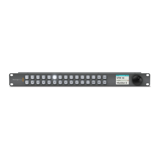
Videohub routers or other network devices. Only 1 rack unit high and less than an inch thick, you can rack-mount Videohub Master Control at the front or at the rear of the rack to leave space for other equipment. -
Page 16: Connecting Usb To Configure The Control Panel
A USB 2.0 connection to a computer is used to configure the network settings of the Videohub Controller. Be aware that the USB port of the Videohub Smart Control is inaccessible once it is installed in a rack. If you are likely to reconfigure Videohub Smart Control network settings periodically, then it may be convenient to permanently connect a USB cable to the unit before installing Videohub Smart Control in a rack. -
Page 17: Control Panel Button Diagnostics
IP address, or if the unit successfully acquires an IP address from the DHCP server. Red flashing light - unit has acquired an IP address and is attempting to connect to the Videohub Server. Make sure the Videohub Server computer is powered on and connected via Ethernet. -
Page 18: Setting Up Your Videohub Controller
Ethernet-equipped Videohub, such as Compact Videohub, without using a network switch. You will also need to complete the IP details for the remote Videohub that you wish to control with your Videohub control panel. The remote Videohub is the Videohub Server. This could refer to a Videohub Server computer or an integrated Videohub Server onboard a Videohub model such as Universal Videohub 72. -
Page 19: Configuring Videohub Master Control
Getting Started with Videohub Controllers Add Videohub Control If you already know the IP address of a Videohub control panel but it hasn't automatically appeared in the Videohub Control Panels pane, you can add the unit manually. Step 1. Press the + (add device) button at the bottom of the Videohub Control Panels pane. -
Page 20: Configuring Videohub Smart Control
Click on each white button in the software interface to configure the source buttons. Step 5. In the Router SDI In A field, enter the number of the Videohub input port to which the source device is connected. If your destination device is receiving dual link HD-SDI or dual stream 3D, Enter the number of the Videohub port to which the SDI device is connected. - Page 21 Click on the desired Destination button to configure it. Step 5. In the Router SDI In A field, enter the number of the Videohub input port to which the source device is connected. If your destination device is receiving dual link HD-SDI or dual stream 3D, you will also need to enter an input port number into the Router SDI In B field.
-
Page 22: Setting Up The Gpi And Tally Interface
Open Videohub Hardware Panel Setup. Step 4. You should see your GPI and Tally Interface with a USB icon next to it in the Videohub Control Panels pane. Give your GPI and Tally Interface a unique name so it can be easily recognized. -
Page 23: Labeling Pushbuttons
Step 3. Gently lift the face plate off the unit. If you have a Videohub Master Control, take care not to pull on the data cable that connects the scroll wheel to the rest of the unit. -
Page 24: Using Videohub Routers
VIDEO CLEAR TAKE Smart Videohub 40 x 40 Smart Videohub 40x40 is a small router with a built in control panel and LCD and is perfect for locations DEST CLEAR TAKE where minimal space is available, such as outside broadcast trucks. It features 40 SDI inputs, 40 SDI outputs, reference input and output, a redundant universal power supply and powerful Videohub routing control software. - Page 25 Using the Smart Videohub 40x40 Control Panel and LCD MENU Smart Videohub 40x40 features a built in control panel and LCD. Routing changes can be made without VIDEO needing a computer by simply using the numbered pushbuttons. Remote router control can also be used.
-
Page 26: Smart Videohub 20X20
CLEAR TAKE Smart Videohub 20x20 is a tiny router with a built in control panel and LCD and is perfect for locations where minimal space is available, such as outside broadcast trucks. It features 20 SDI inputs, 20 SDI RS-422... - Page 27 Using the Smart Videohub 20x20 Control Panel and LCD MENU Smart Videohub 20x20 features a built in control panel and LCD. Routing changes can be made without needing a computer by simply using the numbered pushbuttons. Remote router control can also be used.
-
Page 28: Smart Videohub 12X12
CLEAR TAKE Smart Videohub 12x12 is a tiny router with a built in control panel and LCD and is perfect for locations where minimal space is available, such as outside broadcast trucks. It features 12 SDI inputs, 12 SDI RS-422... - Page 29 Using the Smart Videohub 12x12 Control Panel and LCD MENU Smart Videohub 12x12 features a built in control panel and LCD. Routing changes can be made without needing a computer by simply using the numbered pushbuttons. Remote router control can also be used.
-
Page 30: Universal Videohub 288
CONTROL USB DIAGNOSTIC USB DIAGNOSTIC Universal Videohub 288 ships as an empty rack frame, except for a removable fan tray and fans. All other ETHERNET ETHERNET hardware components, such as SDI interface cards and power supplies, must be purchased and installed... -
Page 31: Universal Videohub 288 Crosspoint Card
A Power Overload light will illuminate on the card if inadequate power is being supplied to the unit for the number of cards installed. You will need a number 01 size Pozidriv screwdriver to install the Universal Videohub 288 Crosspoint card. Router Control Cable Remote router control is performed via 10/100Base-T Ethernet or serial. -
Page 32: Building Universal Videohub 288
Installing a Universal Videohub 288 Crosspoint Card Now that your Universal Videohub 288 has been mounted in a rack, it needs to be fitted with a crosspoint card. The crosspoint card is the brains of Universal Videohub and performs video route and deck control switching. -
Page 33: Installing Interface Cards
Step 2: Gently insert the card along its guides until it plugs firmly into the PCI slot on the motherboard. Step 3: Use a number 02 size Pozidriv screwdriver to secure the card to the Universal Videohub frame. Pages 42-43 provide information on the different interface cards available for your Universal Videohub. -
Page 34: Installing A Universal Videohub 450W Power Card
Videohub 450W Power Card. You will need to connect 3 power supplies for each Universal Videohub 450W Power Card you install in a Universal Videohub 288. You will need to provide a standard IEC cord with a C13 connector for each power supply. - Page 35 Connect an IEC cord from the new power supply to the wall socket and turn on the power. Removing a Power Supply while Universal Videohub 288 is running If you need to remove a faulty power supply while Universal Videohub 288 is running from another power supply, please carry out the removal procedure in the following order: Step 1.
- Page 36 Using Videohub Routers Installing a Universal Videohub 72 Crosspoint Card A single Universal Videohub 72 Crosspoint card can be installed in the left crosspoint card slot of a Universal Videohub 288. The Universal Videohub 72 Crosspoint card is limited to supporting 18 interface cards and does not support crosspoint redundancy.
- Page 37 Use a number 01 size Pozidriv screwdriver to secure the screws on the two levers of the crosspoint card. Step 10. The short length of the Universal Videohub 72 Crosspoint card means that a short blanking plate should also be installed to cover the rest of the long crosspoint slot. The short blanking plate can be secured with a number 02 size Pozidriv screwdriver.
-
Page 38: Universal Videohub 72
USB 2.0 type A to mini B male cable. Universal Videohub 72 ships as an empty rack frame, except for a removable fan tray and fans. All other hardware components, including SDI interface cards, deck control cables, crosspoint card and power supplies must be purchased and installed separately. -
Page 39: Universal Videohub 72 Crosspoint Card
Remote router control is performed via 10/100Base-T Ethernet or serial. If router control is performed via Ethernet, the integrated Videohub Server is used. This means you only need to provide an Ethernet cable to connect Universal Videohub 72 to your Ethernet network switch. -
Page 40: Building Videohub 72
Only 7 RU is required if Universal Videohub 72 is mounted at the top of an open rack. Universal Videohub 72 is 5 rack units high and 6 inches thick. -
Page 41: Installing A Universal Videohub 450W Power Card
If you need to remove or replace a 150W Power Supply while Universal Videohub 72 is still running, power off the brick while being careful to avoid switching off power to the remaining power supplies. -
Page 42: Sdi Interface Card
Using Videohub Routers SDI Interface Card SDI interface cards feature 4 SDI inputs, 4 SDI outputs and a connector for a Universal Videohub Deck Control Cable. All SDI connections support auto detection of SD, HD or 3G-SDI, and reclocking on all SDI outputs. -
Page 43: Universal Videohub Interface Cards
Using Videohub Routers Universal Videohub Interface Cards Universal Videohub Universal Videohub SDI Interface Optical Interface Activity light Activity light MAIN POWER MAIN POWER MAIN POWER +12V 800W +12V +12V 800W Output 1 Output 1 Input 1 Output 2 ALARM POWER OVERLOAD... -
Page 44: Broadcast Videohub
However the Videohub Server computer must remain powered on at all times so that Videohub settings can be modified. You will need to provide a standard USB 2.0 type A-B male cable to connect Broadcast Videohub to the server computer. -
Page 45: Studio Videohub
However the Videohub Server computer must remain powered on at all times so that Videohub settings can be modified. You will need to provide a standard USB 2.0 type A-B male cable to connect Studio Videohub to the server computer. -
Page 46: Compact Videohub
Compact Videohub Compact Videohub is a small router and is perfect when you need a bigger router in a small size, such as in creative post facilities and broadcast trucks. It features 40 SDI inputs, 40 SDI outputs, reference input, redundant power supply connections and powerful Videohub routing control software. -
Page 47: Micro Videohub
Developer Information section of this manual. Micro Videohub is 1 rack unit high and less than an inch thick. You will need to leave enough space in your equipment rack to install the Micro Videohub hardware. You can rack-mount Micro Videohub facing forwards or reversed, or even mount it in the rear of the rack to leave space for other equipment. -
Page 48: Smart Videohub
Third party router controllers can control Smart Videohub via Ethernet, or as an RS-422 slave device, for router crosspoint switching. Smart Videohub is 1 rack unit high and just over an inch thick. You will need to leave enough space in your equipment rack to install the Smart Videohub hardware. You can rack-mount Smart Videohub at the front or at the rear of the rack to leave space for other equipment. - Page 49 Using the Smart Videohub Control Panel Smart Videohub features a built in 32 pushbutton control panel on the front of the router. Routing changes can be made without needing a computer as there is a pushbutton for each SDI input and output on Smart Videohub.
-
Page 50: Controlling Videohub With Software
Launch Videohub Control and click on Settings (the gear icon) and choose "Select Videohub" from the menu. Click on the Videohub that you wish to control. If you completed the section on customizing labels, the names you assigned will appear within the software. - Page 51 Click and drag the window edges to resize Blackmagic Videohub Control to fit your screen size. Drag the Divider Bar up or down to reveal more or less of the "Sources" and "Destinations" areas and use the Scroll Bars to scroll the areas.
- Page 52 Displays the Edit Buttons for editing the pushbuttons. Reset All Displays all of the inputs and outputs of the connected Videohub and replaces customized icons with Click the Settings button to display the above menu. the default icon. Source, destination and deck control settings are maintained.
- Page 53 You may wish to enable the "Use TAKE" button to help prevent unintentional changes to video routes. This destination is unlocked and is available to any Videohub user Once enabled, any attempt to change a video route using a pushbutton will cause a red "TAKE" button on the network.
- Page 54 If you need to unlock a route set by another user, launch Videohub Setup, select the Outputs tab and click the destination's lock icon.
-
Page 55: Touchscreen Computers
When a computer mouse is moved to the top of a Full Screen Pushbutton view, the Videohub menu bar will be revealed. When the mouse is moved away from the menu bar, the menu bar will hide again. As with the i icon, a touchscreen cannot detect a finger hovering towards the top of the display and so the Videohub menu bar will not be revealed automatically. -
Page 56: Apple Ipad
Up to 40 sources and 8 destinations can be displayed in a single Videohub Pushbutton screen on the iPad. Even more sources and destinations can be displayed by flicking the iPad left or right, or tapping to the left or right of the row of dots, to move through multiple Pushbutton screens. - Page 57 If you encounter a gray padlock icon and do not know who locked the video device you can override the lock using the Videohub software on a Mac OS X or Windows computer. When a route is unlocked, the padlock icon will disappear.
-
Page 58: Controlling Videohub With Hardware
Front panel showing a new source has been selected. show "SDI" on its LCD and you don't need to read anything more about routing levels. If your Videohub does include RS-422 remote deck control ports, you can use the LEVEL button on Source SDI 422 Videohub Master Control to reduce the list of sources and destinations by routing level. - Page 59 Controlling Videohub with Hardware How to select devices by typing the Videohub port numbers Source If you've chosen to keep the default labels for all Videohub SDI and remote ports, you can simply type Input 52 CLEAR the port numbers to make a routing change. This method is fast but requires that you remember port Destination numbers or have devised a system for knowing what equipment is connected to each Videohub port.
- Page 60 Videohub Master Control will then return to its idle state with the latest route displayed on the LCD. If any button you have customized for either a source or destination flashes but does not stay lit, Videohub Master Control is preventing you from selecting the button because the equipment type has not been labeled as a source or destination device or does not match the current routing level.
- Page 61 Step 1. Press the DEST button. The destination field will be highlighted blue on the LCD. Step 2. If your Videohub router has RS-422 remote control, press the LEVEL button until you have set the appropriate routing level for your equipment. Otherwise you can skip this step.
- Page 62 Videohub Master Control will then return to its idle state with the latest route displayed on the LCD. If any button you have customized for either a source or destination flashes but does not stay lit, Videohub Master Control is preventing you from selecting the button because the equipment type has not been labeled as a source or destination device or does not match the current routing level.
- Page 63 Step 4. Press and hold the gold DEST button until a lock icon appears in the destination field of the LCD. Destination VTR 1 Step 5. Press DEST again to return Videohub Master Control to its idle state and the destination field TAKE will revert to gray.
-
Page 64: Using Videohub Smart Control As A Cut-Bus Controller
Controlling Videohub with Hardware Using Videohub Smart Control as a Cut-Bus Controller If Videohub Smart Control has been configured as a Cut-Bus controller, the destination device has already been chosen and you only need to choose a video source. Step 1. Select a white video source button. The button will light up to distinguish it from the other sources. -
Page 65: Configuring Gpis
The GPI and Tally Interface has 8 GPIs that provide crosspoint switching. In the example on the left, if GPI 1 detects a contact closure it will switch Input 12 on your Videohub to Output 1. This means when you switch the joystick control on your CCU, video going to Input 12 of your Videohub will be previewed on your monitor. - Page 66 GPI IN 7 GPI OUT The GPI and Tally Interface has two ethernet ports so that you can connect one port to a Videohub and GPI IN 8 use the other port to link other GPI and Tally Interfaces together.
-
Page 67: Getting Help
Blackmagic Design support office. Checking the version currently installed To check which version of Videohub Control is installed on your computer, open the Blackmagic Videohub application. From the "Blackmagic Videohub" menu, select "About Videohub" and note the version number. - Page 68 All three fans should immediately start running. Step 12. Gently dock the rear of the fan tray with the Universal Videohub chassis. Swing up the front of the fan tray and simultaneously push the tray towards the Videohub motherboard until the rear of the fan tray slides into place and the front swings shut.
-
Page 69: Help
The weight of copper-based SDI cables quickly adds up so it is advisable to use your rack to support the cables so that the full cable weight does not place undue stress on the BNC ports of your Videohub. This is particularly important with larger models of Videohub due to the weight of many SDI cables. -
Page 70: Developer Information
A block spans multiple lines and is terminated by a blank line. Each line in the protocol is terminated by a newline character. Upon connection, the Videohub Server sends a complete dump of the state of the device. After the initial status dump, status updates are sent every time the Videohub status changes. - Page 71 In the last two situations, no further information will be sent, unless the situation is rectified. If the Videohub Server detects a new Videohub attached, it will resend all blocks except the protocol preamble to indicate the device has changed, and allow the client to update its cache of server state.
- Page 72 ↵ SERIAL PORT ROUTING:↵ 0 12↵ 1 11↵ … ↵ Videohubs with processing units (only the Workgroup Videohub) send an extra routing block: PROCESSING UNIT ROUTING:↵ 0 5↵ 1 3↵ … ↵ Videohubs with frame buffers (only the Workgroup Videohub) send two extra blocks: FRAME LABELS:↵...
- Page 73 ↵ SERIAL PORT LOCKS:↵ 0 U↵ 1 U↵ … ↵ Videohubs with processing units (only the Workgroup Videohub) send an extra lock block: PROCESSING UNIT LOCKS:↵ 0 U↵ 1 U↵ … ↵ Videohubs with frame buffers (only the Workgroup Videohub) send an extra lock block: FRAME BUFFER LOCKS:↵...
- Page 74 Developer Information Videohubs with serial ports next send a block which describes the direction of each serial port. Each port has a direction of either "control" for the "In (Workstation)" setting, "slave" for "Out (Deck)", or "auto" for "Automatic". SERIAL PORT DIRECTIONS:↵ 0 control↵...
- Page 75 Requesting Changes To update a label, lock or route, the client should send a block of the same form the Videohub Server sends when its status changes. For example, to change the route of output port 8 to input port 3, the client should send the following block: VIDEO OUTPUT ROUTING:↵...
- Page 76 "F" instead of using the usual unlock character "U". For example, to override a lock on port 7: SERIAL PORT LOCKS:↵ 7 F↵ ↵ ACK↵ ↵ SERIAL PORT LOCKS:↵ 7 U↵ ↵ Hardware status blocks can only be sent by the Videohub Server. If a client sends hardware status blocks, they will be ignored.
- Page 77 While the connection to the Videohub Server is established, a client may send a special no-operation command to check that the Videohub Server is still responding: PING:↵ ↵ If the Videohub Server is responding, it will respond with an ACK message as for any other recognized command.
-
Page 78: Saving And Loading Labels With Telnet In Mac Os X
Normally you would use Blackmagic Videohub Setup to save and load labels between different Videohub routers and to backup your videohub settings. However, if for any reason you wish to use the Terminal, the instructions below let you save and load router label configurations via the Terminal. -
Page 79: Saving And Loading Labels With Telnet In Windows
PuTTY which is a free telnet client. Setting up PuTTY Step 1. Start the application and in the "Host Name" field, type the IP of your Videohub and in the "Port" field type "9990", which is the default port number. Step 2. -
Page 80: Videohub Rs-422 Protocol
Videohub RS-422 Protocol General The RS-422 protocol can be used to control many Videohub models as RS-422 slave devices, for router crosspoint switching. This feature is available on any Videohub model with an "RS-422 Control" port. In "Leitch Server" mode, these Videohub models implement the router (server) side of the Leitch Serial Pass-Through Protocol as specified in section 4 of Leitch document SPR-MAN revision D. - Page 81 Developer Information Notifications Once connected, if status reporting is enabled, the client will receive a notification message when a route changes on the Videohub Server. The notifications take one of two forms: Routing change S:0destination,source This message indicates that the specified source port is now routed to the specified destination.
- Page 82 Developer Information Salvo Commands queue route change P:0/destination,source … queue multiple route changes P:0/destination,source/destination-2,source-2 The specified routing changes are added to the current salvo for later execution. request individual port status in salvo P?0destination If a routing change for the specified destination port is queued, the route will be returned as notification.
-
Page 83: Warranty
12 months from the date of purchase. Blackmagic Design warrants that Videohub Master Control and Videohub Smart Control will be free from defects in materials and workmanship for a period of 12 months from the date of purchase. - Page 84 Installation and Operation Manual Videohub Hardware Control Mac OS X ™ Windows ™ September 2014...
- Page 85 This instruction manual contains all the information you’ll need to install your Videohub Control and GPI and Tally Interface, although it’s always a good idea to ask a technical assistant for help if you are not sure what IP addresses are, or if you don’t know much about computer networks.
- Page 86 How to Select Sources and Destinations Videohub Smart Control Using Videohub Smart Control GPI and Tally Interface Using Videohub Smart Control as a Cut-Bus Controller Connecting USB to Setup the Control Panel Using Videohub Smart Control as an XY Controller Plugging into an Ethernet Network...
-
Page 87: Getting Started
Videohub routers or other network devices. Only 1 rack unit high and less than an inch thick, you can rack-mount Videohub Master Control at the front or at the rear of the rack to leave space for other equipment. -
Page 88: Connecting Usb To Setup The Control Panel
A USB 2.0 connection to a computer is used to configure the network settings of the Videohub Controller. Be aware that the USB port of the Videohub Smart Control is inaccessible once it is installed in a rack. If you are likely to reconfigure Videohub Smart Control network settings periodically, then it may be convenient to permanently connect a USB cable to the unit before installing Videohub Smart Control in a rack. -
Page 89: Control Panel Button Diagnostics
IP address, or if the unit successfully acquires an IP address from the DHCP server. Red flashing light - unit has acquired an IP address and is attempting to connect to the Videohub Server. Make sure the Videohub Server computer is powered on and connected via Ethernet. -
Page 90: Installing The Videohub Software
Getting Started Installing the Videohub Software Videohub software runs on the latest Mountain Lion and Mavericks versions of Mac OS X. On the Windows platform, the software runs on both 32 and 64-bit versions of Windows 7 and Windows 8. -
Page 91: Setting Up Your Videohub Controller
Ethernet-equipped Videohub, such as Compact Videohub, without using a network switch. You will also need to complete the IP details for the remote Videohub that you wish to control with your Videohub control panel. The remote Videohub is the Videohub Server. This could refer to a Videohub Server computer or an integrated Videohub Server onboard a Videohub model such as Universal Videohub 72. -
Page 92: Configuring Videohub Master Control
Getting Started Add Videohub Control If you already know the IP address of a Videohub control panel but it hasn't automatically appeared in the Videohub Control Panels pane, you can add the unit manually. Step 1. Press the + (add device) button at the bottom of the Videohub Control Panels pane. -
Page 93: Configuring Videohub Smart Control
Click on each white button in the software interface to configure the source buttons. Step 5. In the Router SDI In A field, enter the number of the Videohub input port to which the source device is connected. If your destination device is receiving dual link HD-SDI or dual stream 3D, Enter the number of the Videohub port to which the SDI you will also need to enter an input port number into the Router SDI In B field. - Page 94 Click on the desired Destination button to configure it. Step 5. In the Router SDI In A field, enter the number of the Videohub input port to which the source device is connected. If your destination device is receiving dual link HD-SDI or dual stream 3D, you will also need to enter an input port number into the Router SDI In B field.
-
Page 95: Setting Up The Gpi And Tally Interface
Open the Videohub Hardware Panel Setup. Step 4. You should see your GPI and Tally Interface with a USB icon next to it in the Videohub Control Panels pane. Give your GPI and Tally Interface a unique name so it can be easily recognized. -
Page 96: Labeling Pushbuttons
Step 3. Gently lift the face plate off the unit. If you have a Videohub Master Control, take care not to pull on the data cable that connects the scroll wheel to the rest of the unit. -
Page 97: Using Videohub Master Control
Front panel showing a new source has been selected. show "SDI" on its LCD and you don't need to read anything more about routing levels. If your Videohub does include RS-422 remote deck control ports, you can use the LEVEL button on Source SDI 422 Videohub Master Control to reduce the list of sources and destinations by routing level. - Page 98 Using Videohub Master Control How to select devices by typing the Videohub port numbers Source If you've chosen to keep the default labels for all Videohub SDI and remote ports, you can simply type Input 52 CLEAR the port numbers to make a routing change. This method is fast but requires that you remember port Destination numbers or have devised a system for knowing what equipment is connected to each Videohub port.
- Page 99 Videohub Master Control will then return to its idle state with the latest route displayed on the LCD. If any button you have customized for either a source or destination flashes but does not stay lit, Videohub Master Control is preventing you from selecting the button because the equipment type has not been labeled as a source or destination device or does not match the current routing level.
- Page 100 How to select devices using the numeric buttons and scroll wheel If you have customized the Videohub port labels with numbers, you can use the numeric buttons and scroll wheel together to find a short list of sources and destinations. This method is fast and intuitive because you only have to scroll through a short list of equipment and you don't have to remember any port numbers.
- Page 101 Videohub Master Control will then return to its idle state with the latest route displayed on the LCD. If any button you have customized for either a source or destination flashes but does not stay lit, Videohub Master Control is preventing you from selecting the button because the equipment type has not been labeled as a source or destination device or does not match the current routing level.
- Page 102 Locking and Unlocking Routes Source SDI 422 Videohub Master Control can lock and unlock any route on your Videohub. In contrast to Videohub Edit 1 CLEAR Smart Control, Videohub Master Control can also unlock any destinations locked by other people using Destination their computer, iPad or Videohub Smart Control.
-
Page 103: Using Videohub Smart Control
Using Videohub Smart Control Using Videohub Smart Control as a Cut-Bus Controller If Videohub Smart Control has been configured as a Cut-Bus controller, the destination device has already been chosen and you only need to choose a video source. Step 1. -
Page 104: Using Gpi And Tally Interface
The GPI and Tally Interface has 8 GPIs that provide crosspoint switching. In the example on the left, if GPI 1 detects a contact closure it will switch Input 12 on your Videohub to Output 1. This means when you switch the joystick control on your CCU, video going to Input 12 of your Videohub will be previewed on your monitor. - Page 105 GPI IN 7 GPI OUT The GPI and Tally Interface has two ethernet ports so that you can connect one port to a Videohub and GPI IN 8 use the other port to link other GPI and Tally Interfaces together.
-
Page 106: Help
Blackmagic Design support office. Checking the version currently installed To check which version of Videohub Control is installed on your computer, open the Blackmagic Videohub application. From the "Blackmagic Videohub" menu, select "About Videohub" and note the version number. -
Page 107: Warranty
12 months from the date of purchase. Blackmagic Design warrants that Videohub Master Control and Videohub Smart Control will be free from defects in materials and workmanship for a period of 12 months from the date of purchase. - Page 108 Operation Manual Videohub Software Control Mac OS X ™ Windows ™ September 2014...
- Page 109 HD-SDI routing. Videohub changes all that and even enables you to pipe 2K film around your studio just like video. We hope you get years of use from your Videohub and have lots of fun connecting everyone in your facility together! This instruction manual should contain all the information you’ll need to install your Videohub, although it’s always a...
- Page 110 Contents Videohub Software Control Manual Getting Started Introducing Blackmagic Videohub Control Installing Videohub Control Mac OS X installation Windows installation Using Blackmagic Videohub Videohub Control Getting to Know the Interface Menus and Buttons Explained Settings Menu Edit Buttons Using Pushbuttons...
-
Page 111: Getting Started
Videohub connections at once. Videohub Control is easy to use because it operates on a single video output at a time. Selecting a destination (output) pushbutton shows which source (input) is connected to it by illuminating the source pushbutton. -
Page 112: Using Blackmagic Videohub Videohub Control
Click and drag the window edges to resize Blackmagic Videohub Control to fit your screen size. Drag the Divider Bar up or down to reveal more or less of the "Sources" and "Destinations" areas and use the Scroll Bars to scroll... -
Page 113: Getting To Know The Interface
Using Blackmagic Videohub Control Getting to Know the Interface Launch Videohub Control and click on the "Select a Videohub" button and then select the Videohub you wish to control. If the Input, Output and Remote connections have not yet been labeled in Blackmagic Videohub Setup, then the source pushbuttons will appear simply as "Input", followed by their respective numbers. -
Page 114: Menus And Buttons Explained
Click the Settings button to display the above menu. Reset All Displays all of the inputs and outputs of the connected Videohub and replaces customized icons with the default icon. Source, destination and deck control settings are maintained. Edit Buttons Add a source or destination pushbutton. -
Page 115: Using Pushbuttons
Using Blackmagic Videohub Control Using Pushbuttons Adding Pushbuttons Select the Settings button and then select "Edit Buttons". Click on the Add button and choose whether to add a source or destination pushbutton. The Set Button window appears and allows you to set the SDI source or destination, RS-422 deck control and the icon for the pushbutton. -
Page 116: Viewing And Switching Routes
Sources area to display the source pushbutton. Switching Routes This destination is unlocked and is available to any Videohub user In order to change the video source from a tape deck to a video camera, press a camera pushbutton on the network. -
Page 117: Locking And Unlocking Routes
If you need to unlock a route set by another user, launch Videohub Setup, select the Outputs tab and click the destination's lock icon. -
Page 118: Help
Blackmagic Design support office. Checking the version currently installed To check which version of Videohub Control is installed on your computer, open the Blackmagic Videohub application. From the "Blackmagic Videohub" menu, select "About Videohub" and note the version number. -
Page 119: Warranty
12 months from the date of purchase. Blackmagic Design warrants that Videohub Master Control and Videohub Smart Control will be free from defects in materials and workmanship for a period of 12 months from the date of purchase.
Need help?
Do you have a question about the Videohub and is the answer not in the manual?
Questions and answers