Table of Contents
Advertisement
Quick Links
Advertisement
Table of Contents

Related Manuals for IDTECK Star RFL200C


Summary of Contents for IDTECK Star RFL200C
-
Page 2: Table Of Contents
Table of Contents ............Table of Contents . - Page 3 ............19 5 LED Color Control .
-
Page 4: Safety Information
Safety Information CAUTION: TO REDUCE THE RISK OF ELECTRIC SHOCK, DO NOT REMOVE COVER (OR BACK) NO USER SERVICEABLE PARTS INSIDE. REFER SERVICING TO QUALIFIE D SERVICE PERSONNEL. This symbol indicates that dangerous voltage consisting a risk of electric shock is pres ent within this unit. - Page 5 3. Do not connect multiple controllers to a single adapter. Exceeding the capacity may cau se abnormal heat generation or fire. 4. Securely plug the power cord into the power receptacle. Insecure connection may caus e fire. 5. When installing the controller, fasten it securely and firmly. The fall of controller may ca use personal injury.
-
Page 6: Important Safety Instructions
IMPORTANT SAFETY INSTRUCTIONS 1. Read these instructions. 2. Keep these instructions. 3. Heed all warnings. 4. Follow all instructions. 5. Do not use this apparatus near water. 6. Clean only with dry cloth. 7. Do not block any ventilation openings. Install in accordance with the manufacturer’s ins tructions. -
Page 7: General
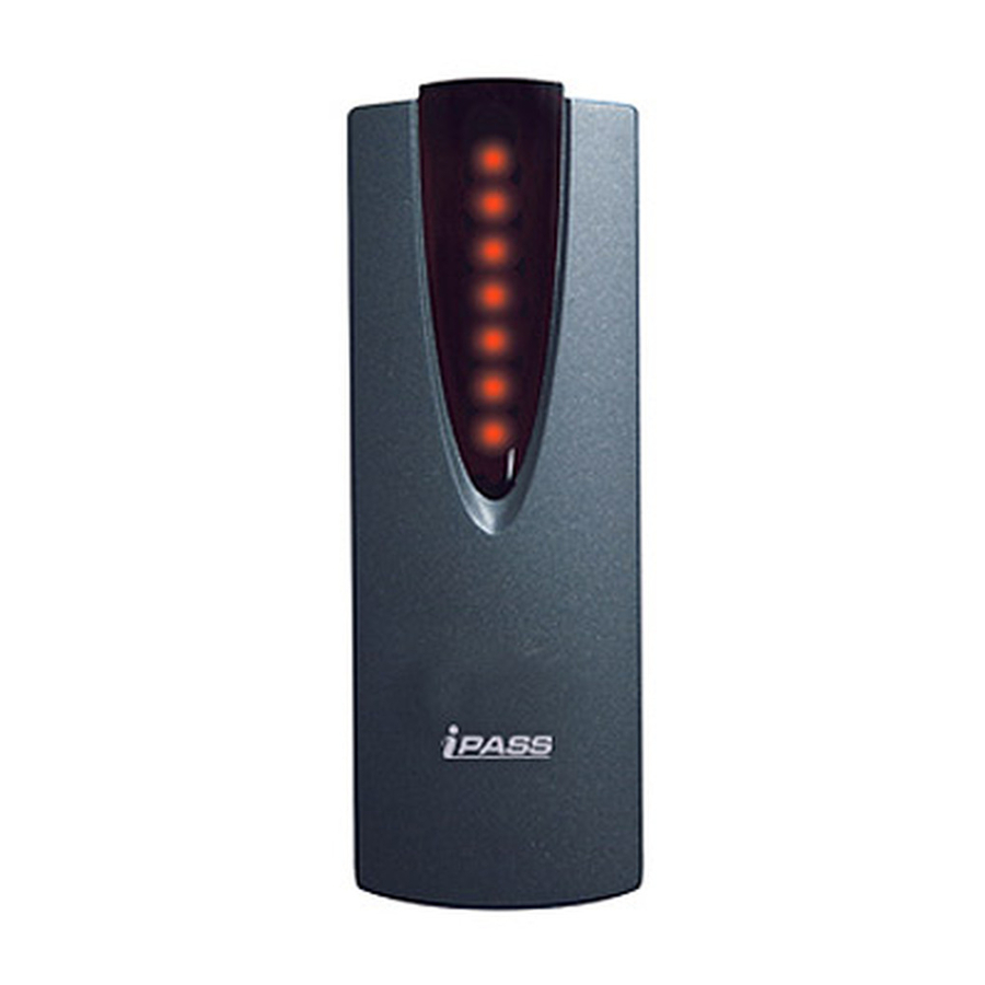
General The Star RFL200C / iPASS IP-RFL200C are an elegant looking and an attractive 4" read range proximity reader built-in Proximity Single Door Access Controller which can be mounted to metal door frame (mullion) or to any flat wall surface. The Star RFL200C / iPASS IP-RFL200C is epoxy potted that ensure you a successful operation even in harsh environments. -
Page 8: Features
Features 125KHz Standalone Proximity Access Controller ● iPASS IP-RFL200C: ASK[EM] Format ● Star RFL200C: PSK Modulation 512 Users ● Network Communication via RS485 (Max.255ch) ● TCP/IP (External LAN Converter required, optional) Wireless (e.g. Bluetooth module required, optional) 512 Users / 256 Event Buffers ●... -
Page 9: Identifying Supplied Parts
Identifying Supplied Parts Please unpack and check the contents of the box. -
Page 10: Specification
Specification Model RFL200C IP-RFL200C Dual 8bit Microprocessor 64KByte Flash ROM Memory Program Memory 4KByte EEPROM Data Mem 512 Users User 256 Event Buffers Event Buffer IDK50 / IMC125: Up to 2 inch (5cm)IDC80 / I IPK50: Up to 2 inch (5 Passive Typ DC170: Up to 4 inch (10cm) IPC80 / IPC170: Up to... - Page 11 10% to 90% relative humidity non-condensing Operating Humidity Dark Pearl Gray Color Polycarbonate Material 45mm x 124m x 19.64mm (1.8” x 4.9” x 0.8”) Dimension (W x H x T) 80g (0.18 lbs) Weight Life Time Warranty FCC, CE, MIC Certification...
-
Page 12: Installation
Installation 1. Drill one 0.5”(12.7mm) hole at the central of the RFL200C / IP-RFL200C on mullion or wall mount. Route the cable of reader module through the central hole. 2. Drill one 0.39"(10mm) in right horizontal and 1.74"(44.4mm) in upper vertical through the central hole. - Page 13 p.10...
-
Page 14: Color Coded & Wiring Table
Color Coded & Wiring Table p.11... -
Page 15: Wire Connection To Controller
Wire Connection to Controller Connecting a power supply Connecting a power supply- Connect +12V of power supply to Red wire. ● Connect GND of power supply to Black wire. ● p.12... -
Page 16: Connecting A Door Lock
Connecting a door lock Connect (+) wire of door lock to +12V wire of power supply. ● Connect (-) wire of door lock to white wire of reader module. ● Connecting an exit button Connect Green wire of exit button input to one wire between wires of exit button. ●... - Page 17 Plug 9-pin connector of converter into COM Port of the PC. ● Install the application software and then run. ● 485 Converter RFL200C / IP-RFL200C 485(-) Orange wire 485(+) Gray wire RS485 Communication port connection p.14...
-
Page 18: Network Connection To The Access Controller
Network connection to the access controller You can install up to 255 Units of RFL200C / IP-RFL200C.as in the below figure. Max. 255 units (Board ID : 1~255) can be installed in a loop. ● Able to connect directly via RS485 or RS232 converter. ●... -
Page 19: Set Up Hardware
Set up Hardware All parameters of Star RFL200C / iPASS IP-RFL200C are set by the application software. Set up “System Address” and “Normal” or “Toggle Mod e”. 1. Choose “System Name” and “System Address” on drop down list. 2. Click “Normal Mode” or “Toggle Mode”. -
Page 20: Set "In / Out Point
Set “In / Out Point” 1. Choose “Door Open Time (sec)” of 1 to 99sec. 2. Choose “Lock Type” one whether Power Fail Safe or Power Fail Secure. 3. If clicking “Save” button, one door among “System (Door) Address” is checked. 4. -
Page 21: System Initialization
System Initialization StarRFL200C / iPASS IP-RFL200C is initialized by the software. System Initialization p.18... -
Page 22: Led Color Control
LED Color Control The Star RFL200C / iPASS IP-RFL200C can change its LED color to red or green by the applic ation software p.19 Set up Hardware... -
Page 23: Operation
Operation When the RFL200C / IP-RFL200C is powered on, 1. All LEDs are lit red or green, then they flash on and off twice and then turn off. 2. Then, red LEDs are lit sequentially from bottom to top. 3. The RFL200C / IP-RFL200C beeps once. When a registered tag is read on the RFL200C / IP-RFL 200C or the exit button is pressed, 1. -
Page 24: When A Tag Is Read On The Rfl200C / Ip-Rfl200C While The Door Is Open
1. All LEDs are lit red, then they flash on and off twice and stay on. The RFL200C / IP-RFL200C beeps twice. When a tag is read on the RFL200C / IP-RFL200C whil e the door is open. 1. The first two LEDs from the top still stay lit green, indicating the open status of the doo 2. -
Page 25: To Initialize The Rfl200C / Ip-Rfl200C
Using this software, you can also adjust or cha nge “Normal Mode” / “Toggle Mode”, “Door Open Tim e” and “LED Color Control”. Refer to the “STAR RFL200C” software manual for more information. Besides the operations described above, users can register or delete cards using the STAR p.22 RFL200C software, as well. -
Page 26: Fcc Registration Information
FCC REGISTRATION INFORMATION FCC Requirements Part 15 Caution: Any changes or modifications in construction of this device which are not expressly approved by the responsible for compliance could void the user's authority to operate the e quipment. NOTE: This device complies with Part 15 of the FCC rules. Operation is subject to the following two conditions;... -
Page 27: Rma Request
RMA Request If you have any questions or problems regarding the RMA services, please contact us using t he contact information below. Friendly representatives at IDTECK are always standing by to provide the best after sales services. IDTECK Headquarter 5F, Ace Techno Tower B/D, 684-1, Deungchon-Dong,...
Need help?
Do you have a question about the Star RFL200C and is the answer not in the manual?
Questions and answers