
Related Manuals for Beckhoff EL2911


Summary of Contents for Beckhoff EL2911
- Page 1 Operating Instructions for EL2911 TwinSAFE Potential Supply Terminal with 4 digital fail-safe inputs Version: 1.0.0 Date: 2018-08-24...
-
Page 3: Table Of Contents
Safety concept ......................... 12 2.2.3 The fail-safe principle (Fail Stop) .................. 13 3 Product description.......................... 14 EL2911 - TwinSAFE potential supply terminal with 4 digital fail-safe inputs ........ 14 Intended use ............................ 15 Requirements for the potential group .................... 17 Technical data .......................... 19 Safety parameters ........................... 20 Safe inputs and outputs ........................ 20... - Page 4 4.5.3 Flash code display ...................... 45 4.5.4 Diagnosis History...................... 45 4.5.5 Diag History tab ....................... 48 Maintenance ............................ 50 Service life ............................ 51 Decommissioning .......................... 51 Firmware update of TwinSAFE products .................. 52 5 Appendix .............................. 55 Support and Service ........................ 55 Certificates............................ 56 Version: 1.0.0 EL2911...
-
Page 5: Foreword
Product features Only the product features specified in the current user documentation are valid. Further information given on the product pages of the Beckhoff homepage, in emails or in other publications is not authoritative. Disclaimer The documentation has been prepared with care. The products described are subject to cyclical revision. For that reason the documentation is not in every case checked for consistency with performance data, standards or other characteristics. -
Page 6: Safety Instructions
Offenders will be held liable for the payment of damages. All rights reserved in the event of the grant of a patent, utility model or design. Delivery conditions In addition, the general delivery conditions of the company Beckhoff Automation GmbH & Co. KG apply. Safety instructions 1.2.1... -
Page 7: Description Of Safety Symbols
1.0.0 • Certificate added • First release 0.0.5 • Overview screen updated 0.0.4 • Connection added • Parameter description updated 0.0.3 • Requirements for the potential group added 0.0.2 • Update after review 0.0.1 • First draft EL2911 Version: 1.0.0... -
Page 8: Version History Of The Twinsafe Product
A description of how a firmware (software) update can be performed can be found in chapter Firmware update of TwinSAFE products [} 52]. Date Software ver- Hardware Modifications sion version 16.08.2018 First release of the EL2911 Version: 1.0.0 EL2911... -
Page 9: System Description
System description The Beckhoff EtherCAT Terminal system The Beckhoff EtherCAT Terminal system is used for decentralized connection of sensors and actuators to a controller. The components of the Beckhoff EtherCAT Terminal system are mainly used in industrial automation and building management systems. As a minimum, a bus station consists of an EtherCAT Coupler and connected EtherCAT Terminals. -
Page 10: Ethercat Bus Coupler
Fig. 2: Bus Coupler (EtherCAT) Connection technology Bus Coupler Wiring Spring-loaded system Connection cross-section 0.08 mm² ... 2.5 mm², stranded wire, solid wire Fieldbus connection EtherCAT Power contacts 3 spring contacts Current load 10 A Nominal voltage 24 V Version: 1.0.0 EL2911... -
Page 11: Ethercat Terminals
The operating voltage is passed on to following terminals via three power contacts. Terminal strip can be split into galvanically isolated groups by means of potential supply terminals as required. The supply terminals play no part in the control of the terminals, and can be inserted at any locations within the terminal strip. EL2911 Version: 1.0.0... -
Page 12: Twinsafe
2.2.1 The I/O construction kit is extended safely The integrated TwinSAFE safety solution is the logical continuation of the open, PC-based Beckhoff control philosophy. Due to their modularity and versatility, the TwinSAFE components fit seamlessly into the Beckhoff control system. The I/O components are available in the formats Bus Terminal, EtherCAT Terminal, EtherCAT plug-in module and EtherCAT Box. -
Page 13: The Fail-Safe Principle (Fail Stop)
The basic rule for a safety system such as TwinSAFE is that failure of a part, a system component or the overall system must never lead to a dangerous condition. CAUTION Safe state The safe state of the TwinSAFE system is always the switched-off and de-energized state. EL2911 Version: 1.0.0... -
Page 14: Product Description
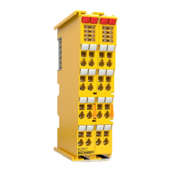
EL2911 - TwinSAFE potential supply terminal with 4 digital fail-safe inputs The EL2911 is a safe potential supply terminal for the power contacts for a downstream potential group. In addition, it has 4 fail-safe inputs for sensors with potential-free contacts for 24 V The EL2911 meets the requirements of IEC 61508:2010 SIL 3 and EN ISO 13849-1:2015 (Cat 4, PL e). -
Page 15: Intended Use
. Failure to observe this can result in a loss of safety. WARNING Commissioning test Before the EL2911 can be used for the safety task, the user must carry out a commissioning test so that sensor and actuator wiring errors can be ruled out. EL2911... - Page 16 EN 60529, so that the requirement for contamination level 3 according to EN 60664-1 can be reduced to level 2. • The TwinSAFE components must be supplied by a SELV/PELV power supply unit with a maximum volt- age of U <= 36 V Version: 1.0.0 EL2911...
-
Page 17: Requirements For The Potential Group
• Excluding a line short-circuit fault (see following alternatives) CAUTION Non-reactive EtherCAT Terminals In the potential group connected through the EL2911, only non-reactive standard terminals must be used. A list the non-reactive EtherCAT Terminals can be found in the Beckhoff Information System under http://in- fosys.beckhoff.de... -
Page 18: Fig. 6 Protected Wiring
All conductors connected to the non-safe standard terminals are permanently installed and protected from external damage, e.g. through a cable duct or an armored conduit. CAUTION Fault exclusion The machine manufacturer or the user is solely responsible for the correct execution and evaluation of the applied alternatives. Version: 1.0.0 EL2911... -
Page 19: Technical Data
In switched-off state, external feeds are detected above 5 V. Input process image 6 byte Output process image 6 byte EL2911 supply voltage (PELV) 24 V (–15% / +20%) Signal voltage "0" inputs -3 V ... 5 V (EN 61131-2, type 3) see chapter Characteristic curve of the inputs [} 20]... -
Page 20: Safety Parameters
NOTE Safe inputs in Cat.4 / PL e If two safe input channels in category 4 structure are to be used, any of the EL2911 channels can be used. Characteristic curve of the inputs The characteristic curve of the inputs is similar to type 3 according to EN 61131-2. -
Page 21: Dimensions
Product description Fig. 7: Characteristic curve of the inputs Dimensions Fig. 8: EL2911 dimensions Width: 24 mm (side-by-side installation) Height: 100 mm Depth: 68 mm EL2911 Version: 1.0.0... -
Page 22: Operation
Please ensure that the digital TwinSAFE components are only transported and stored under the specified environmental conditions (see technical data). 4.2.3 Mechanical installation DANGER Risk of injury! Bring the bus system into a safe, de-energized state before starting installation, disassembly or wiring of the devices! Version: 1.0.0 EL2911... -
Page 23: Fig. 9 Spring Contacts Of Beckhoff I/O Components
• Each bus station must be terminated on the right side with the EL9011 or EL9012 end cap to ensure the protection class and ESD protection. Fig. 9: Spring contacts of Beckhoff I/O components 4.2.3.2 Control cabinet / terminal box The TwinSAFE terminals must be installed in a control cabinet or terminal box with IP54 protection class according to IEC 60529 as a minimum. -
Page 24: Fig. 10 Installation Position And Minimum Distances
The key parameter is always the maximum permitted internally measured temperature of 110°C, above which the TwinSAFE components switch to safe state and report an error. The internal temperature can be read from the TwinSAFE components via CoE. Version: 1.0.0 EL2911... - Page 25 The EL2904 has a rather high waste heat, due to the possibly high output current of the connected actuators. EL1904 Even the EL1904 has a rather high waste heat, although the external load by clock outputs and safe inputs is rather low. EL2911 Version: 1.0.0...
-
Page 26: Fig. 11 Thermally Unfavorable Arrangement Of The Twinsafe Terminals
TwinSAFE terminals by the adjacent power supply units increases the internal terminal temperature, which can lead to the maximum permissible temperature being exceeded. This leads to a diagnosis message "overtemperature”. Fig. 11: Thermally unfavorable arrangement of the TwinSAFE terminals Version: 1.0.0 EL2911... -
Page 27: Fig. 12 Thermally Favorable Arrangement Of The Twinsafe Terminals
Bring the bus terminal system into a safe, powered down state before starting installation, disassembly or wiring of the Bus Terminals! Mounting The Bus Couplers and Bus Terminals are attached to commercially available 35 mm mounting rails (according to EN 60715) by applying slight pressure: EL2911 Version: 1.0.0... -
Page 28: Fig. 13 Installation On The Mounting Rail
For fastening mounting rails with a height of 7.5 mm under the terminals and couplers, use flat fastening components such as countersunk head screws or blind rivets. Removal Fig. 14: Removal of mounting rails Version: 1.0.0 EL2911... -
Page 29: Electrical Installation
PE power contact The power contact labelled PE can be used as a protective earth. For safety reasons this contact mates first when plugging together, and can ground short-circuit currents of up to 125 A. EL2911 Version: 1.0.0... -
Page 30: Fig. 15 Pe Power Contact
The PE power contact must not be used for other potentials! 4.2.4.2 Overvoltage protection If protection against overvoltage is necessary in your plant, provide a surge filter for the voltage supply to the Bus Terminal blocks and the TwinSAFE terminals. Version: 1.0.0 EL2911... -
Page 31: Fig. 16 Connection Of A Cable To A Terminal Point
See the following table for the suitable wire size width. Wire size width (single core wires) 0.08 ... 2.5 mm Wire size width (fine-wire conductors) 0.08 ... 2.5 mm Wire size width (conductors with a wire end sleeve) 0.14 ... 1.5 mm Wire stripping length 8 ... 9 mm EL2911 Version: 1.0.0... -
Page 32: Fig. 17 El2911 - Pin Assignment
Operation 4.2.4.4 EL2911 pin assignment Fig. 17: EL2911 - pin assignment Terminal point Input / Out- Signal Input 1+ (clock output) Input 1- (safe input) Input 3+ (clock output) Input 3- (safe input) Input 2+ (clock output) Input 2- (safe input) -
Page 33: Fig. 18 Cable Routing
The common routing of signals together with other clocked signals in a common cable also reduces the maximum propagation, since crosstalk of the signals can occur over long cable lengths and cause diagnostic messages. EL2911 Version: 1.0.0... -
Page 34: Configuration Of The Terminal In Twincat
See TwinCAT automation software documentation. 4.3.3 Adding an EL2911 An EL2911 is added in exactly the same way as any other Beckhoff EtherCAT Terminal. Open TwinSAFE Terminals item in the list and select the EL2911. Fig. 19: Adding an EL2911 Version: 1.0.0... -
Page 35: Using The Integrated Twinsafe Logic Functions
4.3.4 Using the integrated TwinSAFE Logic functions On delivery, the EL2911 behaves like a safe TwinSAFE I/O slave, which can be used as an alias device within a TwinSAFE Logic, e.g. EL6910. Alternatively, the local logic function of the EP2911 can be used. To this end please create a TwinSAFE project in the Safety Editor and select the EL2911 as the target system. -
Page 36: Address Settings On Twinsafe Terminals With 1023 Possible Addresses
TwinSAFE terminal. TwinSAFE addresses between 1 and 1023 are available. DIP switch Address 1023 WARNING TwinSAFE address Each TwinSAFE address may only be used once within a network / a configuration! The address 0 is not a valid TwinSAFE address! Version: 1.0.0 EL2911... -
Page 37: Alias Devices
The alias devices are created in the safety project when the dialog is closed via OK. Alternatively, the user can create the alias devices individually. To this end select Add and New item from the context menu, followed by the required device. EL2911 Version: 1.0.0... -
Page 38: El2911 Parameters In Twincat
Fig. 24: Creating alias devices by the user 4.3.7 EL2911 parameters in TwinCAT After creating the alias device, it can be parameterized according to the user specifications. The FSoE address is set under the Linking tab, and the link to the physical device is created. -
Page 39: Fig. 26 Connection Tab Of The Alias Device
Operation Fig. 26: Connection tab of the alias device The Safety Parameters tab contains the parameters of the EL2911 to be set. The output is parameterized via parameter 0x8000. The inputs are configured via the objects 0x8010 and 0x8011. Fig. 27: EL2911 parameters... - Page 40 Internal test pulses can have a length of up to 2 ms and cannot can be switched off. 8011:0B Channel4.DiagTestPulseFilterTime 0x0002 / 0.1 ms Input filter for the test pulse signal Version: 1.0.0 EL2911...
-
Page 41: El2911 Process Image
4.3.8 EL2911 process image The process image of the EL2911 consists 6 bytes of process data in the input and the output. Fig. 28: EL2911 process image The assignment of the individual signals in the safe data is listed in the following table. -
Page 42: Twinsafe Reaction Times
This results in the following equation for the typical reaction time: with, for example Worst-case reaction time The worst case reaction time is the maximum time required to switch off the actuator in the case of an error. Version: 1.0.0 EL2911... -
Page 43: Fig. 30 Worst-Case Reaction Time
This error is detected at the output following the expiry of the watchdog time and leads to the switch-off. This results in the following equation for the worst-case reaction: with, for example EL2911 Version: 1.0.0... -
Page 44: Diagnosis
Operation Diagnosis 4.5.1 Status LEDs Fig. 31: EL2911 status and diagnostics LEDs Color Description Input 1 green Status display for the respective input and output Input 2 LED lights up: Input/output is set Input 3 LED not lit: Input/output is not set... -
Page 45: Flash Code Display
Both the control entries and the history itself can be found in the CoE object 0x10F3. The entry Newest Message (0x10F3:02) contains the subindex of 0x10F3, which contains the latest diagnostic message, e.g. 0x06 for diagnostic message 1. EL2911 Version: 1.0.0... - Page 46 TwinSAFE device. The age of the diagnostic message can be deduced by calculation with the current timestamp from the CoE object 0x10F8. Bits 5 to 7 reserved Bits 8 to 15 Number of parameters in this diagnostic message Version: 1.0.0 EL2911...
-
Page 47: Fig. 32 Esi/Xml Message Text
The sending of emergency messages to the EtherCAT master is activated by adding the CoE object 0x10F3:05 to the startup list (Transition IP, value 0x0001). If new diagnostic messages arrive, they are entered in object 0x10F3 and additionally sent by emergency to the EtherCAT master. Fig. 33: Startup list EL2911 Version: 1.0.0... -
Page 48: Diag History Tab
Errors within the logic, the function blocks, the connections or the component itself are stored with a corresponding time stamp. Fig. 34: Diag history Use the Advanced… button to open the advanced settings. Here, the user can customize the behavior of the diag history. Fig. 35: Diag history – advanced settings Version: 1.0.0 EL2911... - Page 49 Messages with status Error are not stored in the diag history Emergency In addition to saving the message in the diag history, an emergency object is also sent and displayed in the TwinCAT logger window. Overwrite / Acknowledge Mode This setting is currently not supported. EL2911 Version: 1.0.0...
-
Page 50: Maintenance
If the TwinSAFE component was subjected to unacceptable soiling it may no longer be operated! WARNING Have soiled terminals checked! Cleaning of the TwinSAFE component by the user is not permitted! Please send soiled terminals to the manufacturer for inspection and cleaning! Version: 1.0.0 EL2911... -
Page 51: Service Life
• Housing components (polycarbonate, polyamide (PA6.6)) are suitable for plastic recycling. • Metal parts can be sent for metal recycling. • Electronic parts such as disk drives and circuit boards must be disposed of in accordance with national electronics scrap regulations. EL2911 Version: 1.0.0... -
Page 52: Firmware Update Of Twinsafe Products
TwinSAFE component is deleted and replaced by a new version. The latest firmware can be downloaded from the Beckhoff website or requested from Beckhoff Support. The versions are available in an encrypted form and can only be loaded onto the matching TwinSAFE product. -
Page 53: Fig. 37 Firmware Update Of Twinsafe Products - Part 1
Click the button (1) in the TwinCAT system to enter Config mode. Confirm the query with OK (2). After that a further window appears which must be confirmed with Yes (Ja) (3). Deactivate the "Free Run" with No (Nein) (4). The system is now in "Configuration mode". Fig. 37: Firmware update of TwinSAFE products - Part 1 EL2911 Version: 1.0.0... -
Page 54: Fig. 38 Firmware Update Of Twinsafe Products - Part 2
After successful completion you must click OK (12) in the concluding "Function Succeeded" window. You can then switch the system back to Run mode and use the TwinSAFE system. Fig. 39: Firmware update of TwinSAFE products - Part 3 Version: 1.0.0 EL2911... -
Page 55: Appendix
Beckhoff's branch offices and representatives Please contact your Beckhoff branch office or representative for local support and service on Beckhoff products! The addresses of Beckhoff's branch offices and representatives round the world can be found on her internet pages: http://www.beckhoff.com You will also find further documentation for Beckhoff components there. -
Page 56: Certificates
Appendix Certificates Version: 1.0.0 EL2911... - Page 57 Slot and key system and screwless (spring-loaded) connection system........Fig. 2 Bus Coupler (EtherCAT)......................Fig. 3 Overview of EtherCAT Terminals ....................Fig. 4 EL2911 - TwinSAFE potential supply terminal with 4 fail-safe inputs.......... Fig. 5 External load..........................Fig. 6 protected wiring ........................... Fig. 7 Characteristic curve of the inputs ....................
Need help?
Do you have a question about the EL2911 and is the answer not in the manual?
Questions and answers