Sign In
Upload
Manuals
Brands
Beckhoff Manuals
Touch terminals
EL34x3 Series
Beckhoff EL34x3 Series Manuals
Manuals and User Guides for Beckhoff EL34x3 Series. We have
1
Beckhoff EL34x3 Series manual available for free PDF download: Documentation
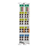
Beckhoff EL34x3 Series Documentation (200 pages)
3-phase power measurement terminal
Brand:
Beckhoff
| Category:
Touch terminals
| Size: 7 MB
Table of Contents
Table of Contents
3
1 Foreword
7
Product Overview - Power Measurement Terminals
7
Notes on the Documentation
7
Safety Instructions
9
Documentation Issue Status
10
Version Identification of Ethercat Devices
11
Fig. 1 EL5021 el Terminal, Standard IP20 IO Device with Serial/ Batch Number and Revision ID (Since 2014/01)
13
Fig. 2 EK1100 Ethercat Coupler, Standard IP20 IO Device with Serial/ Batch Number
13
Fig. 3 CU2016 Switch with Serial/ Batch Number
13
Fig. 4 EL3202-0020 with Serial/ Batch Number 26131006 and Unique ID-Number 204418
14
Fig. 5 EP1258-00001 IP67 Ethercat Box with Batch Number/ Date Code 22090101 and Unique Se- Rial Number 158102
14
Fig. 6 EP1908-0002 IP67 Ethercat Safety Box with Batch Number/ Date Code 071201FF and Unique Serial Number 00346070
14
Fig. 7 EL2904 IP20 Safety Terminal with Batch Number/ Date Code 50110302 and Unique Serial Num- Ber 00331701
14
Fig. 8 ELM3604-0002 Terminal with Unique ID Number (QR Code) 100001051 and Serial/ Batch Num- Ber 44160201
15
2 Product Overview
16
Introduction
16
Fig. 9 EL3413
16
Fig. 10 EL3413-0001
16
Fig. 11 EL3413-0120
17
Technical Data
18
Introduction
19
El3433
19
Technical Data
20
Basic Function Principles
21
Measuring Principle
21
RMS Value Calculation
21
Fig. 13 Voltage U and Current I Curves
21
Effective Power Measurement
22
Apparent Power Measurement
22
Fig. 14 Power S(T) Curve
22
Fig. 15 U(T), I(T), P(T) Curves with Phase Shift Angle Φ
23
Sign for Power Measurement
24
Fig. 16 Four-Quadrant Representation of Active/Reactive Power in Motor and Generator Mode
24
Sign of the Energy Values
25
Frequency Measurement
25
Current Transformer
25
Start
26
3 Basics Communication
27
Ethercat Basics
27
Ethercat Cabling - Wire-Bound
27
General Notes for Setting the Watchdog
28
Fig. 17 System Manager Current Calculation
28
Fig. 18 Ethercat Tab -> Advanced Settings -> Behavior -> Watchdog
29
Ethercat State Machine
30
Fig. 19 States of the Ethercat State Machine
31
Coe Interface
32
Fig. 20 "Coe Online " Tab
33
Fig. 21 Startup List in the Twincat System Manager
34
Fig. 22 Offline List
35
Fig. 23 Online List
35
Distributed Clock
37
4 Installation
38
Instructions for ESD Protection
38
Installation on Mounting Rails
38
Fig. 24 Spring Contacts of the Beckhoff I/O Components
38
Fig. 25 Attaching on Mounting Rail
39
Fig. 26 Disassembling of Terminal
40
Connection
41
Connection System
41
Fig. 27 Power Contact on Left Side
41
Fig. 28 Standard Wiring
42
Fig. 29 Pluggable Wiring
42
Fig. 30 High Density Terminals
42
Wiring
44
Fig. 31 Connecting a Cable on a Terminal Point
44
Shielding
45
Installation Positions
45
Fig. 32 Recommended Distances for Standard Installation Position
46
Fig. 33 Other Installation Positions
47
Positioning of Passive Terminals
48
UL Notice
48
Fig. 34 Correct Positioning
48
Fig. 35 Incorrect Positioning
48
El34X3 - Leds and Connection
50
El3413-0000
50
Fig. 36 EL3413-0000 Leds
50
Fig. 37 EL3413-0000 Connection
51
El3413-0001
53
Fig. 38 EL3413-0001 Leds
53
Fig. 39 EL3413-0001 Connection
54
El3413-0120
56
Fig. 40 EL3413-0120 Leds
56
Fig. 41 EL3413-0120 Connection
57
El3433-0000
59
5 Commissioning
62
Twincat Quick Start
62
Twincat 2
87
Twincat 3
87
Twincat Development Environment
87
Installation of the Twincat Real-Time Driver
87
Notes Regarding ESI Device Description
93
Twincat ESI Updater
97
Distinction between Online and Offline
97
OFFLINE Configuration Creation
98
ONLINE Configuration Creation
103
Ethercat Subscriber Configuration
111
General Notes - Ethercat Slave Application
120
Process Data
128
Sync Manager (SM)
128
Operating Modes and Settings
131
Predefined PDO Assignment
133
Start-Up and Parameter Configuration
133
Settings
133
Measurements
135
Scaling Factors
139
Notices on Analog Specifications
140
Full Scale Value (FSV)
141
Measuring Error/ Measurement Deviation
141
Temperature Coefficient Tk [Ppm/K]
142
Single-Ended/Differential Typification
143
Common-Mode Voltage and Reference Ground (Based on Differential Inputs)
148
Dielectric Strength
148
Temporal Aspects of Analog/Digital Conversion
149
Object Description and Parameterization
152
Restore Object
152
Configuration Data
153
Command Object
153
Configuration Data (Vendor-Specific)
155
Fig. 12 EL3433
155
Input Data
158
Output Data
163
Information and Diagnostic Data
163
Standard Objects
165
6 Diagnostics - Basic Principles of Diag Messages
173
7 Appendix
183
Ethercat al Status Codes
183
Firmware Compatibility
183
Firmware Update El/Es/Em/Elm/Epxxxx
184
Device Description ESI File/Xml
185
Firmware Explanation
188
Updating Controller Firmware *.Efw
189
FPGA Firmware *.Rbf
190
Simultaneous Updating of Several Ethercat Devices
194
Restoring the Delivery State
195
Support and Service
196
List of Illustrations
197
Advertisement
Advertisement
Related Products
Beckhoff EL3413-0000
Beckhoff EL3413-0001
Beckhoff EL3413-0120
Beckhoff EL3433
Beckhoff EL34 Series
Beckhoff EL3443-0013
Beckhoff EL3453
Beckhoff EL3483
Beckhoff EL3483-0060
Beckhoff EL3443
Beckhoff Categories
Touch terminals
Industrial PC
Control Unit
Industrial Equipment
Control Panel
More Beckhoff Manuals
Login
Sign In
OR
Sign in with Facebook
Sign in with Google
Upload manual
Upload from disk
Upload from URL