
Related Manuals for Carrier Aquaforce 30XA302


Summary of Contents for Carrier Aquaforce 30XA302
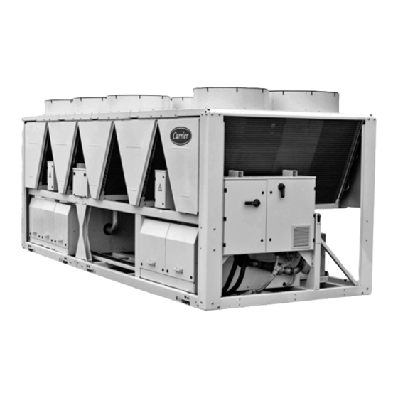
- Page 1 INSTALLATION, OPERATION AND MAINTENANCE INSTRUCTIONS Unit with options 23A, 258 and 279 Air-Cooled Screw Chillers 30XA “A” Nominal cooling capacity: 267-1682 kW 50 Hz Original document...
-
Page 2: Table Of Contents
CONTENTS 1 - INTRODUCTION ..................................4 1.1 - Installation safety considerations ............................4 1.2 - Equipment and components under pressure ........................5 1.3 - Maintenance safety considerations ............................5 1.4 - Repair safety considerations ..............................7 2 - PRELIMINARY CHECKS ..............................8 2.1 - Check equipment received .............................. - Page 3 7 - WATER CONNECTIONS ..............................32 7.1 - Operating precautions ................................32 7.2 - Victaulic water connections ..............................33 7.3 - Flow control .................................... 34 7.4 - Evaporator water box bolt tightening..........................34 7.5 - Frost protection ..................................34 7.6 - Operation of two units in master/slave mode (option 58) ....................34 7.7 - Pump characteristics ................................
-
Page 4: Introduction
The fluid may then be decomposed into toxic residues when Carrier strongly recommends employing a specialised subjected to the flame: company to unload the machine. -
Page 5: Equipment And Components Under Pressure
(locate the control element in the 1.3 - Maintenance safety considerations stop position). Carrier recommends the following drafting for a logbook (the If a relief valve is removed for checking or replacement table below should not be considered as reference and does not... - Page 6 F-Gas, N°517/2014 Recommissioning of the equipment. Ensure that the refrigerant is never released to the Consult Carrier Service for this type of test. Carrier atmosphere during installation, maintenance or mentions here only the principle of a test without equipment disposal.
-
Page 7: Repair Safety Considerations
1.4 - Repair safety considerations Avoid spilling liquid refrigerant on skin or splashing it into the eyes. Use safety goggles and safety gloves. Wash any spills from the skin with soap and water. If liquid All installation parts must be maintained by the personnel in charge, in order to avoid material deterioration and injuries refrigerant enters the eyes, immediately and abundantly to people. -
Page 8: Preliminary Checks
The refrigerant lines can break under the weight and release refrigerant, causing personal injury. Do not climb on a machine. Use a platform, or staging to work at higher levels. Use mechanical lifting equipment (crane, hoist, winch, etc.) to lift or move heavy components. For lighter components, use lifting equipment when there is a risk of slipping or losing your balance. - Page 9 2.2.2 - Siting the unit 2.2.3 - Checks before system start-up The machine must be installed in a place that is not accessible Before the start-up of the refrigeration system, the complete to the public or protected against access by non-authorised installation, including the refrigeration system must be persons.
-
Page 10: Dimensions, Clearances
3 - DIMENSIONS, CLEARANCES 3.1 - 30XA 252-352 - MCHE heat exchanger (standard) and 30XA 252-302 - Cu/Al heat exchanger (option 254/255) 3.2 - 30XA 402-452-504 - MCHE heat exchanger (standard) and 352-452 - Cu/Al heat exchanger (option 254/255) Legend NOTES: All dimensions are given in mm. -
Page 11: 30Xa 502 Mche Heat Exchanger (Standard) And 30Xa 502 Cu/Al Heat Exchanger (Option 254/255)
3.3 - 30XA 502 MCHE heat exchanger (standard) and 30XA 502 Cu/Al heat exchanger (option 254/255) 3.4 - 30XA 602-802-854-904 MCHE heat exchanger (standard) and 30XA 602-702 Cu/Al heat exchanger (option 254/255) Legend NOTES: All dimensions are given in mm. Drawings are not contractually binding. Required clearances for maintenance (see note) Before designing an installation, consult the certified Recommended space for evaporator tube removal... -
Page 12: 30Xa 852-902 Mche Heat Exchanger (Standard) And 30Xa 752-852 Cu/Al Heat Exchanger (Option 254/255)
3.5 - 30XA 852-902 MCHE heat exchanger (standard) and 30XA 752-852 Cu/Al heat exchanger (option 254/255) 3.6 - 30XA 1002 MCHE heat exchanger (standard) and 30XA 902-1002 Cu/Al heat exchanger (option 254/255) Legend NOTES: All dimensions are given in mm. Drawings are not contractually binding. Required clearances for maintenance (see note) Before designing an installation, consult the certified Recommended space for evaporator tube removal... -
Page 13: 30Xa 1112, 1212, 1312, 1382 Mche Heat Exchanger (Standard) And 30Xa 1112, 1212, 1312, 1382 Cu/Al Heat Exchanger (Option 254/255)
3.7 - 30XA 1112, 1212, 1312, 1382 MCHE heat exchanger (standard) and 30XA 1112, 1212, 1312, 1382 Cu/Al heat exchanger (option 254/255) 11962 2253 1500 1500 Legend NOTES: All dimensions are given in mm. Drawings are not contractually binding. Before designing an installation, consult the certified Required clearances for maintenance (see note) dimensional drawings, available on request. -
Page 14: 30Xa 1402-1502 Module 1/2 - Mche Heat Exchanger (Standard) And 30Xa 1402-1502 Module 1/2 - Cu/Al Heat Exchanger (Option 254/255)
3.8 - 30XA 1402-1502 module 1/2 - MCHE heat exchanger (standard) and 30XA 1402-1502 module 1/2 - Cu/Al heat exchanger (option 254/255) To the water inlet of module 2 3.9 - 30XA 1402-1502 module 2/2 - MCHE heat exchanger (standard) and 30XA 1402-1502 module 2/2 - Cu/Al heat exchanger (option 254/255) Water inlet (to be connected to the water outlet of module 1) Module 1... -
Page 15: 30Xa 1702 Module 1/2 - Mche Heat Exchanger (Standard) And 30Xa 1702 Module 1/2 - Cu/Al Heat Exchanger (Option 254/255)
3.10 - 30XA 1702 module 1/2 - MCHE heat exchanger (standard) and 30XA 1702 module 1/2 - Cu/Al heat exchanger (option 254/255) To the water inlet of module 2 3.11 - 30XA 1702 module 2/2 - MCHE heat exchanger (standard) and 30XA 1702 module 2/2 - Cu/Al heat exchanger (option 254/255) Water inlet (to be connected to the water outlet of module 1) -
Page 16: Multiple Chiller Installation
If h < H (2.3 m), minimum S = 3 m row, arranged as shown in the example below, to avoid recycling of warm air from one unit to another. If h > H or S < 3 m, contact your Carrier distributor to 1.5 m 1,5 m 1.5 m... -
Page 17: Physical And Electrical Data For 30Xa Units
4 - PHYSICAL AND ELECTRICAL DATA FOR 30XA UNITS 4.1 - Physical data 30XA 252-852 - standard units and units with option 119* 30XA Sound levels - Standard unit Sound power level*** dB(A) Sound pressure level at 10 m**** dB(A) Standard unit + option 279* Sound power level*** dB(A) -
Page 18: Physical Data 30Xa 904-1702 - Standard Units And Units With Option 119* (Continued)
4.1 - Physical data 30XA 904-1702 - standard units and units with option 119* (continued) 30XA 1002 1112 1212 1312 1382 1402 1502 1702 Sound levels - Standard unit Sound power level*** dB(A) Sound pressure level at 10 m**** dB(A) Standard unit + option 279* Sound power level*** dB(A) -
Page 19: Physical Data 30Xa 252-902 - Units With Option 254 And 255
11.7 11.7 11.7 11.7 Evaporator Flooded multi-pipe type Water volume Maximum pressure 1000 1000 1000 1000 1000 1000 1000 1000 1000 1000 1000 1000 † Weights are guidelines only. For sizes 1402 to 1702 weight of modules 1 and 2. The refrigerant charge is given on the unit nameplate. ** Options: 119 = high energy efficiency, 254 = units with copper/aluminium coils, 255 = units with copper/aluminium coils without slots. *** In dB ref=10 W, (A) weighting. Declared dualnumber noise emission values in accordance with ISO 4871 (with an associated uncertainty of +/-3dB(A)). Measured in accordance with ISO 9614-1 and certified by Eurovent. **** In dB ref 20µPa, (A) weighting. Declared dualnumber noise emission values in accordance with ISO 4871 (with an associated uncertainty of +/-3dB(A)). For information, calculated from the sound power level Lw(A). † Max. water-side operating pressure without hydronic module. Notes: 1. Unit sizes 30XA 1402 to 1702 are supplied in two field-assembled modules. 2. Option 119 (high energy efficiency) can be used together with options 254 and 255. Contact your Carrier representative to obtain the performances. -
Page 20: Physical Data 30Xa 1002-1502 - Units With Option 254 And 255** (Continued)
Weights are guidelines only. For sizes 1402 to 1702 weight of modules 1 and 2. The refrigerant charge is given on the unit nameplate. ** Options: 119 = high energy efficiency, 254 = units with copper/aluminium coils, 255 = units with copper/aluminium coils without slots. *** In dB ref=10-12 W, (A) weighting. Declared dualnumber noise emission values in accordance with ISO 4871 (with an associated uncertainty of +/-3dB(A)). Measured in accordance with ISO 9614-1 and certified by Eurovent. **** In dB ref 20µPa, (A) weighting. Declared dualnumber noise emission values in accordance with ISO 4871 (with an associated uncertainty of +/-3dB(A)). For information, calculated from the sound power level Lw(A). † Max. water-side operating pressure without hydronic module. Notes: 1. Unit sizes 30XA 1402 to 1702 are supplied in two field-assembled modules. 2. Option 119 (high energy efficiency) can be used together with options 254 and 255. Contact your Carrier representative to obtain the performances. 4.3 - Short-circuit stability current for all units 30XA Short-circuit stability current (TN system)* Circuits A + B** Circuits C + D** Units with option 81 30XA 1002 1112... -
Page 21: Electrical Data
4.4 - Electrical data 30XA 252-852 - standard units or units with option 81 30XA Power circuit Nominal power supply V-ph-Hz 400-3-50 ± 10% Control circuit 24 V via internal transformer Maximum start-up current* Circuit 1** Circuit 2** Option 81 Nominal start-up current*** Circuit 1** Circuit 2** Option 81... -
Page 22: Electrical Data (Continued)
4.4 - Electrical data (continued) 30XA 252-852 - units with option 119 or units with option 119 and option 81 30XA Power circuit Nominal power supply V-ph-Hz 400-3-50 ± 10% Control circuit 24 V via internal transformer Maximum start-up current* Circuit 1** Circuit 2** Option 81 Nominal start-up current***... -
Page 23: Electrical Data (Continued)
4.4 - Electrical data (continued) 30XA 252-902 - units with options 254 and 255 or units with options 254 and 255 and option 81 30XA Power circuit Nominal power supply V-ph-Hz 400-3-50 ± 10% Control circuit 24 V via internal transformer Maximum start-up current* Circuit 1** Circuit 2** Option 81... -
Page 24: Electrical Data (Continued)
4.4 - Electrical data (continued) 30XA 252-902 - units with options 254 and 255 + option 119 or units with options 254 and 255 + option 119 + option 81 30XA Power circuit Nominal power supply V-ph-Hz 400-3-50 ± 10% Control circuit 24 V via internal transformer Maximum start-up current* Circuit 1**... -
Page 25: Compressor Electrical Data
Altitude less than or equal to 2000 m (for hydronic module, see the conditions described above, or if there are other conditions which paragraph 4.7 in the IOM) should be considered, always contact your local Carrier representative. Presence of hard solids, class AE3* (no significant dust present) Presence of corrosive and polluting substances, class AF1 (negligible) The required protection level for this class is IP43BW (according to reference C ompetence of persons: BA4 (Persons wise); 30XA machines are not... -
Page 26: Electrical Data, Optional Hydronic Module
I - Altitudes above sea level < 1000 †† II - Ambient air temperature °C < 40 IV - Maximum air temperature °C Please refer to the operating conditions given in this manual or in the specific conditions in the Carrier selection programs. V - Potentially explosive atmospheres Non-ATEX environment Motors of single and dual high-pressure pumps for 30XA units (options 116B and116C) No.** Description*** 30XA Nominal efficiency at full load and nominal voltage 86.1 88.6 88.6 90.1... -
Page 27: Electrical Connection
2 of the table on the next page. supply voltage or excessive phase imbalance constitutes abuse which will invalidate the Carrier warranty. If the The calculations are based on the maximum machine phase imbalance exceeds 2% for voltage, or 10% for current (see electrical data tables). -
Page 28: Field Control Wiring
5.6 - Field control wiring IMPORTANT: Field connection of interface circuits may Refer to the 30XA/30XAS/30XW Touch Pilot control lead to safety risks: Any control box modification must manual and the certified wiring diagram supplied with the maintain equipment conformity with local regulations. unit for the field control wiring of the following features: Precautions must be taken to prevent accidental electrical •... -
Page 29: Application Data
6 - APPLICATION DATA Evaporator water temperature °C Minimum Maximum Water entering temperature at start-up 6.1 - Operating range Water entering temperature during operation Water leaving temperature during operation 30XA standard unit and 30XA0504, 854, 904 with Note: If the leaving water temperature is below 4 °C, a glycol/water solution or the option 119. frost protection option must be used. -
Page 30: Variable Flow Evaporator
6.4 - Variable flow evaporator 6.6 - Maximum system water volume Variable evaporator flow can be used in standard 30XA Units with hydronic module incorporate an expansion chillers. The chillers maintain a constant leaving water tank that limits the water volume. The table below gives tem-perature under all flow conditions. -
Page 31: Evaporator Pressure Drop Curve
6.8 - Evaporator pressure drop curve Sizes 252-602 Legend 504 - 502 504-502 Water flow rate, l/s Sizes 702-1702 Legend 854 - 852 904 - 902 1002 1112 1212 1312 854- 10 1382 11 1402 904- 12 1502 13 1702 1002 1112 1212 1312 Water flow rate, l/s... -
Page 32: Water Connections
Verify then, the need to install sacrificial anodes. In case additives or other fluids than those recommen- ded by Carrier are used, ensure that the fluids are not considered as a gas, and that they belong to class 2, as... -
Page 33: Victaulic Water Connections
7.2 - Victaulic water connections Inlet/outlet diameters without hydronic module 30XA Standard Nominal diameter Actual outside diameter 141.3 141.3 141.3 141.3 141.3 141.3 141.3 141.3 168.3 168.3 168.3 168.3 168.3 168.3 Options 5, 6 and 100A Nominal diameter Actual outside diameter 114.3 114.3 114.3 114.3... -
Page 34: Flow Control
(a purge connec- application. If adjustment is necessary, it must be carried tion is available somewhere on the heat exchanger out by qualified personnel trained by Carrier Service. water box in case the machine is not perfectly level). •... -
Page 35: Pump Characteristics
30XA with configuration: Leaving water control Legend Master unit Slave unit Control boxes of the master and slave units Water inlet Water outlet Water pumps for each unit (included as standard for units with hydronic module) Additional sensors for leaving water control, to be connected to channel 1 of the slave boards of each master and slave unit CCN communication bus Connection of two additional sensors 7.7 - Pump characteristics 7.7.1 - Available external static pressure (hydronic module option) Data applicable for: - Fresh water 20 °C... -
Page 36: Free-Cooling Option (Option 118A)
8 - FREE-COOLING OPTION (OPTION 118A) 8.1 - Physical data, 30XA units with free-cooling option (option 118A) 30XA with Option 118A 1002 Operating weight with option 279 or 257 kg 3740 3780 3820 4673 4743 5174 6097 6247 6547 6847 7308 7648 8226... -
Page 37: Heat Reclaim Condenser Option (Option 50)
9 - HEAT RECLAIM CONDENSER OPTION (OPTION 50) 9.1 - Physical data, 30XA units with heat reclaim condenser option 30XA heat reclaim mode 1002 3920 3960 3970 4930 5050 5550 6670 6730 7130 7350 7890 8340 8950 Operating weight* Condenser diameter 12+12 12+12 14+12... - Page 38 9.2.2 - 30XA 402-452 - heat reclaim option Legend All dimensions are given in mm. Required clearances for maintenance (see note) Recommended space for evaporator tube removal Water inlet for standard unit For options 5, 6, 100A, 100C, 107 refer to the certified drawing. Water outlet for standard unit For options 5, 6, 100A, 100C, 107 refer to the certified drawing.
- Page 39 9.2.4 - 30XA 602-802 - heat reclaim option Legend All dimensions are given in mm. Required clearances for maintenance (see note) Recommended space for evaporator tube removal Water inlet for standard unit For options 5, 6, 100A, 100C, 107 refer to the certified drawing. Water outlet for standard unit For options 5, 6, 100A, 100C, 107 refer to the certified drawing. Air outlet – do not obstruct Power supply and control connection Control circuit connection for option 158 9.2.5 - 30XA 852-902 - heat reclaim option Heat reclaim condenser ATTENTION: The condenser connection sleeves are not...
- Page 40 9.2.6 - 30XA 1002 - heat reclaim option Legend All dimensions are given in mm. Required clearances for maintenance (see note) Recommended space for evaporator tube removal Water inlet for standard unit For options 5, 6, 100A, 100C, 107 refer to the certified drawing. Water outlet for standard unit For options 5, 6, 100A, 100C, 107 refer to the certified drawing. Air outlet – do not obstruct Power supply and control connection Control circuit connection for option 158 Heat reclaim condenser ATTENTION: The condenser connection sleeves are not NOTES:...
-
Page 41: Condenser Location
9.3 - Condenser location 9.5 - Operating limits for stable operation (no mode changeover) All heat reclaim condensers are located between the air-cooled condensers on the upper part of the chassis, 9.5.1 - Cooling only mode support-ed by two cross rails. The water inlet and outlet are Please refer to the earlier chapters in this manual: on the same side. -
Page 42: Operating Limits For Changeover Between Modes
9.6 - Operating limits for changeover between modes ATTENTION: Mode changes may lead to higher sound levels than the levels at stable operation. From cooling only to heat reclaim and vice versa. Depending on the mode selected (heat reclaim or cooling), Heat reclaim condenser water temperature the logic compares the water entering temperature required °C... -
Page 43: Frost Protection
• Castrol Icematic SW220 (Carrier specification • An indication of any modification or repair must be PP47-32) shown in the monitoring and maintenance file. -
Page 44: High-Pressure Safety Switch
This is also the case for PZHH must be reset with a blunt tool with a diameter of the products originally supplied by Carrier. less than 6 mm. Insert this tool into the opening on the pressure switch and push the reset button in this location. -
Page 45: Electronic Expansion Valve (Exv)
According to the Regulation No. 640/2009 and amendment 4/2014 implementing Directive 2005/32/EC with regard to ecodesign requirements for electric motors. Product 30XA Option Standard option 119 Motor type Asynchronous Asynchronous Number of poles Nominal input frequency Nominal voltage Number of phases Motor included in the application domain of the regulation 640/2009 and amendment 4/2014 Sales leaflet for exemption °C... - Page 46 30XA fan arrangement 30XA 902 30XA 252-352 30XA 352 (options 254/255) 30XA 902 (options 254/255) 30XA 402-452-504 30XA 1002 30XA 502 30XA 1112 2.4* 30XA 602 30XA 1212 2.4* 30XA 702-904 30XA 1312-1382 1.5* 2.5* 1.6* 2.6* 30XA 752 - 802-854 30XA 752-802 (options 254/255) x = Circuit number y = Start-up order...
-
Page 47: Main Options
(Not available for the pumps, drain valve and water flow control valve. For size 504) more details, refer to the dedicated chapter Dx Free Cooling system 118A Patented Carrier free-cooling system with cooling Energy savings for applications with cooling demand 252-1002 on two circuits micro-pump on both refrigerant circuits. Operation throughout the entire year (Not available for the without glycol, no extra free-cooling coil. See Dx... - Page 48 230 V electrical plug 230 V AC power supply source provided with plug Permits connection of a laptop or an electrical device 252-1702 socket and transformer (180 VA, 0.8 Amps) during unit commissioning or servicing Carrier Connect link 3G Router board Enabler for Carrier Connect service offer 252-1702 (BSS regions only) NOTE 1: Require option 149 NOTE 2: When more than one machine is installed on...
-
Page 49: Standard Maintenance
See note “Any deviation or non-observation ...” in the ext HVAC unit null and void, and the manufacturer, Carrier SCS will no longer be held responsible. column. This level requires specific know-how in the electrical, hydronic and mechanical fields. -
Page 50: Tightening Torques For The Main Electrical Connections
13.4 - Tightening torques for the main electrical connections 13.4.1 - Tightening torques for the main electrical connections Component Designation Value in the unit (N·m) Screw on bus bar, customer connection L1/L2/L3 Soldered screw PE, customer connection (M12) Tunnel terminal screw, compressor contactor Contactor 3RT103_ Contactor 3RT104_ Contactor 3RT105_... - Page 51 Removal of fibres that obstruct the surfaces • Clean the condenser face by spraying the coil evenly Fibres and dirt collected on the coil surface must be removed und in a stable manner from bottom to top, directing with a vacuum cleaner. If you do not have a vacuum cleaner, the water jet at right angles to the coil.
-
Page 52: Evaporator Maintenance
13.7 - Evaporator maintenance The switch that has been selected for detecting reverse rotation is Carrier part number HK01CB001. This switch opens the contacts when the pressure falls below 7 kPa. The Check that: • The insulating foam is intact and securely in place. -
Page 53: Start-Up Checklist For 30Xa Liquid Chillers (Use For Job File)
14 - START-UP CHECKLIST FOR 30XA LIQUID CHILLERS (USE FOR JOB FILE) Preliminary information Job name: ....................................... Location: ........................................ Installing contractor:..................................... Distributor: ......................................Unit Model: .................... Compressors Circuit A Circuit B Model number ................Model number ................Serial number ................Serial number ................Motor number ................ - Page 54 WARNING: Operation of the chiller with an improper supply voltage or excessive phase imbalance constitutes abuse and will invalidate the Carrier warranty. If the phase imbalance exceeds 2% for voltage, or 10% for current, contact your local electricity supply at once and ensure that the chiller is not switched on until corrective measures have been taken.
- Page 56 Order No: 13452-76, 07.2015 - Supersedes order No: 13452-76, 12.2014. Manufacturer: Carrier SCS, Montluel, France. Manufacturer reserves the right to change any product specifications without notice. Printed in the European Union.
Need help?
Do you have a question about the Aquaforce 30XA302 and is the answer not in the manual?
Questions and answers