Sign In
Upload
Manuals
Brands
Carrier Manuals
Chiller
Aquaforce 30XA1502
Carrier Aquaforce 30XA1502 Manuals
Manuals and User Guides for Carrier Aquaforce 30XA1502. We have
1
Carrier Aquaforce 30XA1502 manual available for free PDF download: Installation, Operation And Maintenance Instructions
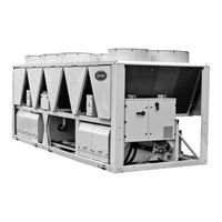
Carrier Aquaforce 30XA1502 Installation, Operation And Maintenance Instructions (56 pages)
Air-Cooled Screw Chillers
Brand:
Carrier
| Category:
Chiller
| Size: 6.48 MB
Table of Contents
Table of Contents
2
1 Introduction
4
Installation Safety Considerations
4
Equipment and Components under Pressure
5
Maintenance Safety Considerations
5
Repair Safety Considerations
7
2 Preliminary Checks
8
Check Equipment Received
8
Moving and Siting the Unit
8
3 Dimensions, Clearances
10
30XA 252-352 - MCHE Heat Exchanger (Standard) and 30XA 252-302 - Cu/Al Heat Exchanger (Option 254/255)
10
30XA 402-452-504 - MCHE Heat Exchanger (Standard) and 352-452 - Cu/Al Heat Exchanger (Option 254/255)
10
30XA 502 MCHE Heat Exchanger (Standard) and 30XA 502 Cu/Al Heat Exchanger (Option 254/255)
11
30XA 602-802-854-904 MCHE Heat Exchanger (Standard) and 30XA 602-702 Cu/Al Heat Exchanger
11
(Option 254/255)
11
30XA 852-902 MCHE Heat Exchanger (Standard) and 30XA 752-852 Cu/Al Heat Exchanger (Option 254/255)
12
30XA 1002 MCHE Heat Exchanger (Standard) and 30XA 902-1002 Cu/Al Heat Exchanger (Option 254/255)
12
30XA 1112, 1212, 1312, 1382 MCHE Heat Exchanger (Standard) and 30XA 1112, 1212, 1312, 1382 Cu/Al Heat Exchanger (Option 254/255)
13
30XA 1402-1502 Module 1/2 - MCHE Heat Exchanger (Standard) and 30XA 1402-1502 Module 1/2 - Cu/Al Heat Exchanger (Option 254/255)
14
30XA 1402-1502 Module 2/2 - MCHE Heat Exchanger (Standard) and 30XA 1402-1502 Module 2/2 - Cu/Al Heat Exchanger (Option 254/255)
14
30XA 1702 Module 1/2 - MCHE Heat Exchanger (Standard) and 30XA 1702 Module 1/2 - Cu/Al Heat Exchanger (Option 254/255)
15
30XA 1702 Module 2/2 - MCHE Heat Exchanger (Standard) and 30XA 1702 Module 2/2 - Cu/Al Heat Exchanger (Option 254/255)
15
Multiple Chiller Installation
16
Distance to the Wall
16
4 Physical and Electrical Data for 30Xa Units
17
Physical Data 30XA 252-852 - Standard Units and Units with Option 119
17
Physical Data 30XA 904-1702 - Standard Units and Units with Option 119* (Continued)
18
Physical Data 30XA 252-902 - Units with Option 254 and 255
19
Physical Data 30XA 1002-1502 - Units with Option 254 and 255** (Continued)
20
Short-Circuit Stability Current for All Units
20
Electrical Data
21
Electrical Data (Continued)
22
Electrical Data (Continued)
23
Electrical Data (Continued)
24
Compressor Electrical Data
25
Compressor Usage Per Circuit (A, B, C, D)
25
Electrical Data, Optional Hydronic Module
26
5 Electrical Connection
27
Power Supply
27
Voltage Phase Imbalance (%)
27
Power Connection/Disconnect Switch
27
Recommended Wire Sections
27
Power Cable Entry
27
Field Control Wiring
28
6 Application Data
29
Operating Range
29
Minimum Chilled Water Flow (Units Without Hydronic Module)
29
Maximum Chilled Water Flow (Units Without Hydronic Module)
29
Variable Flow Evaporator
30
System Minimum Water Volume
30
Maximum System Water Volume
30
Evaporator Water Flow Rate
30
Evaporator Pressure Drop Curve
31
7 Water Connections
32
Operating Precautions
32
Victaulic Water Connections
33
Flow Control
34
Evaporator Water Box Bolt Tightening
34
Frost Protection
34
Operation of Two Units in Master/Slave Mode (Option 58)
34
Pump Characteristics
35
8 Free-Cooling Option (Option 118A)
36
Physical Data, 30XA Units with Free-Cooling Option (Option 118A)
36
Operating Limits
36
Operation
36
9 Heat Reclaim Condenser Option (Option 50)
37
Physical Data, 30XA Units with Heat Reclaim Condenser Option
37
Dimensions, Clearances
37
Condenser Location
41
Condenser Water Connections
41
Operating Limits for Stable Operation (no Mode Changeover)
41
Operating Limits for Changeover between Modes
42
Flow Control
42
Heat Reclaim Operation
42
Condenser Pump Selection
42
Frost Protection
43
10 Fans with Available Pressure (Option 10)
43
11 Major System Components and Operation Data
43
Direct-Drive Twin-Screw Compressor with Variable Capacity Slide Valve
43
Pressure Vessels
43
High-Pressure Safety Switch
44
Condensers
44
Fans
44
Electronic Expansion Valve (EXV)
45
Moisture Indicator
45
Filter Drier
45
Sensors
45
Service Valve (Option 92)
45
Power Factor Correction Capacitors (Option 231)
45
12 Main Options
47
13 Standard Maintenance
49
Level 1 Maintenance
49
Level 2 Maintenance
49
Level 3 (or Higher) Maintenance
49
Tightening Torques for the Main Electrical Connections
50
Tightening Torques for the Main Bolts and Screws
50
Condenser Coil
50
Evaporator Maintenance
52
Compressor Maintenance
52
Precaution for Compressor Power Supply Bus Bar Connection
52
Check of Power Factor Correction Capacitors
52
14 Start-Up Checklist for 30Xa Liquid Chillers (Use for Job File)
53
Advertisement
Advertisement
Related Products
Carrier AQUAFORCE 30XA140
Carrier Aquaforce 30XA1402
Carrier AquaForce 30XA102 Series
Carrier AquaForce 30XA142 Series
Carrier AquaForce 30XA182 Series
Carrier Aqua Force 30XA 1302
Carrier Aqua Force 30XA 1352
Carrier Aqua Force 30XA 1202
Carrier Aqua Force 30XA 1102
Carrier AquaForce 30XA162 Series
Carrier Categories
Air Conditioner
Heat Pump
Furnace
Thermostat
Chiller
More Carrier Manuals
Login
Sign In
OR
Sign in with Facebook
Sign in with Google
Upload manual
Upload from disk
Upload from URL