Carrier AQUAFORCE 30XA080-500 Product Data
Air-cooled liquid chillers 80 to 500 nominal tons
Hide thumbs
Also See for AQUAFORCE 30XA080-500:
Table of Contents
Advertisement
Copyright 2005 Carrier Corporation
Product
Data
Well exceeds ASHRAE 90.1 Standards.
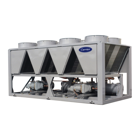
AQUAFORCE™
30XA080-500
Air-Cooled Liquid Chillers
80 to 500 Nominal Tons
AquaForce chillers were designed
from the ground up to meet the effi-
ciency demands of today and the
future by providing premium air-
cooled chiller packages for contrac-
tors, consulting engineers and
building owners.
• Rotary screw compression
• R-134a HFC refrigerant
• Quiet AeroAcoustic™ fan system
• Easy to use Comfort Link™ controls
Features/Benefits
AquaForce 30XA chillers
provide best full load and
part load performance in a
single chassis from 80 to
500 tons.
Premium performance
The Aqua Series of chillers are
Carrier's most efficient air-cooled mod-
els. The AquaForce chiller is one of
the most affordable air-cooled chillers
to operate (and maintain). The
AquaForce chiller offers full load EER
(Energy Efficiency Ratio) up to 10.7
and IPLV (Integrated Part-Load Value)
up to 15.1. High-efficiency rotary
screw compressors with infinitely vari-
able slide valves allow the chillers to
exactly match actual load conditions,
delivering exceptional part load perfor-
mance. The AquaForce chillers will
deliver superior efficiency through all
operating ranges to keep costs and
demand charges down. This excep-
tional performance will have a signifi-
cant impact on energy savings and cost
of ownership.
Form 30XA-2PD
Advertisement
Chapters
Table of Contents

Related Manuals for Carrier AQUAFORCE 30XA080-500


Summary of Contents for Carrier AQUAFORCE 30XA080-500
- Page 1 80 to 500 tons. Premium performance The Aqua Series of chillers are Carrier’s most efficient air-cooled mod- els. The AquaForce chiller is one of the most affordable air-cooled chillers to operate (and maintain). The AquaForce chiller offers full load EER (Energy Efficiency Ratio) up to 10.7...
-
Page 2: Table Of Contents
The following features are All AquaForce units are ready to be one-piece unit from 80 to 500 tons. also provided to help ensure reliable used with the Carrier Comfort Net- The base rail is industrial-quality performance: work (CCN). -in. cold-rolled steel for maximum Multiple independent circuits structural integrity. -
Page 3: Features/Benefits
Features/Benefits (cont) AEROACOUSTIC™ FAN vs. PROPELLER FAN PENETRATES BUILDING STRUCTURE 1080 1600 2400 4000 6300 8000 1/3 OCTAVE BAND CENTER FREQUENCY (Hz) AEROACOUSTIC FAN PROPELLER FAN AEROACOUSTIC FAN VS PROPELLER FAN NAVIGATOR™ DISPLAY SMOOTH ROTARY COMPRESSOR LOW-NOISE AEROACOUSTIC FAN TWIN-SCREW DESIGN... -
Page 4: Model Number Nomenclature
Model number nomenclature AQUAFORCE™ CHILLER MODEL NUMBER DESIGNATION 30XA 30XA – Air-Cooled AquaForce™ Chiller Packaging/Security Options L – Coil Face Shipping Protection (CFSP) 0 – CFSP, Skid Design Series 1 – Skid, Top Crate, Bag 3 – CFSP, Coil Trim Panels Unit Sizes 4 –... -
Page 5: Ari Capacity Ratings
ARI* capacity ratings (English and SI) COOLER COOLER CAPACITY FULL LOAD IPLV 30XA UNIT TOTAL POWER FLOW RATE PRESSURE DROP SIZE (kW) (TONS) (kW) (EER) (COP) (EER) (COP) (gpm) (L/s) (ft wg) (kPa) 75.4 265.3 83.7 14.2 180.4 11.4 11.4 34.1 84.4 297.0... -
Page 6: Physical Data
Physical data 30XA080-500 — ENGLISH UNIT 30XA OPERATING WEIGHT (lb) Al-Cu Condenser Coils 7,674 8,704 8,931 9,071 9,216 11,505 11,748 13,590 13,712 14,727 REFRIGERANT TYPE R-134a, EXV Controlled System Refrigerant Charge (lb) Ckt A/Ckt B/Ckt C 86/86/— 97/97/— 108/108/— 135/108/— 135/135/—... - Page 7 30XA080-500 — SI UNIT 30XA OPERATING WEIGHT (kg) Al-Cu Condenser Coils 3,445 3,906 4,009 4,068 4,129 5,159 5,263 6,087 6,135 6,587 REFRIGERANT TYPE R-134a, EXV Controlled System Refrigerant Charge (kg) Ckt A/Ckt B/Ckt C 39/39/— 44/44/— 49/49/— 49/44/— 102/102/— 91.6/52.2/— 102/61.2/— 93/93/—...
- Page 8 Physical data (cont) UNIT WEIGHTS — STANDARD UNITS UNIT WEIGHTS — ENGLISH MOUNTING WEIGHT (lb) 30XA UNIT SIZE Total 2023 1759 1773 2039 7594 MOUNTING WEIGHT (lb) 30XA UNIT SIZE Total 1243 2145 1023 2115 1262 8611 1269 2202 1054 2171 1288 8837...
- Page 9 30XA080 30XA220-300 30XA090-120 30XA325-350 30XA400-450 30XA140-160 30XA180-200...
-
Page 10: Options And Accessories
Options and accessories ITEM FACTORY-INSTALLED OPTION FIELD-INSTALLED ACCESSORY Condenser Coil and Fan Options Aluminum Fins/Pre-coated Aluminum Fins E-Coat High Ambient Temperature Option Controls/Communication Options BACnet™ Translator Control Chillervisor System Manager III Multi-Unit Control DataLINK™ Control DataPort™ Control Energy Management Module Convenience Outlet LON Translator Control Remote Enhanced Display... - Page 11 ™ control is an interface device that allows a monitoring and diagnostics. non-Carrier control device to read values in the system ele- ments connected to the Carrier Comfort Network (CCN) Chillervisor System Manager III multi-unit control Communication Bus using ASCII over a RS-232 connec- allows sequencing of between two and eight chillers in tion.
-
Page 12: Dimensions
Dimensions... -
Page 14: Dimensions
Dimensions (cont) - Page 16 Dimensions (cont)
- Page 18 Dimensions (cont)
- Page 20 Dimensions (cont)
- Page 22 Dimensions (cont)
- Page 24 Dimensions (cont)
- Page 26 Dimensions (cont)
- Page 28 Dimensions (cont)
-
Page 30: Selection Procedure
Selection procedure Carrier’s Packaged Chiller Builder Selection Program pro- • Consider wind baffles if average wind speed is greater vides quick, easy selection of Carrier’s air-cooled liquid than 5 mph (8 km/h). chillers. The program considers specific temperature, fluid • Consider higher loop volumes, 6 to 10 gallons per and flow requirements among other factors such as fouling nominal ton (6.5 to 10.8 l/kW). - Page 31 To select a 30XA chiller, use the Packaged Chiller Builder program or follow one of the procedures below. I Determine 30XA unit size and operating con- ditions required to meet given capacity at ENGLISH given conditions. I Determine 30XA unit size and operating con- Given: ditions required to meet given capacity at Capacity .
-
Page 32: Capacity
Selection procedure (cont) ETHYLENE GLYCOL PERFORMANCE PROPYLENE GLYCOL PERFORMANCE CORRECTION FACTORS AND SOLUTION CORRECTION FACTORS AND SOLUTION CRYSTALLIZATION POINTS CRYSTALLIZATION POINTS Correction factors apply to published chilled water Correction factors apply to published chilled water performance ratings from 40 to 60 F performance ratings from 40 to 60 F (4.4 to 15.6 C) LCWT. -
Page 33: Performance Data
Performance data COOLER PRESSURE DROP CURVES 30XA080-120 (149.5) 090,100 110 (134.6) (119.6) (104.7) (89.7) (74.8) (59.8) (44.9) (29.9) (15) (107.6) (215.2) (322.8) (430.4) (538) (645.6) Cooler Flow, GPM (l/kW) 30XA140-240 (179.4) (149.5) (119.6) (89.7) (59.8) (29.9) 1000 1200 1400 (215.2) (430.4) (645.6) (860.8) -
Page 34: Condenser Entering Air Temp
Performance data (cont) 30XA PACKAGED AIR-COOLED CHILLER RATINGS TABLE — ENGLISH CONDENSER ENTERING AIR TEMPERATURE (F) 30XA LCWT (F) UNIT Cooler Cooler Cooler Cooler SIZE Power Flow Rate Power Flow Rate Power Flow Rate Power Flow Rate Tons Tons Tons Tons (gpm) (gpm) - Page 35 30XA PACKAGED AIR-COOLED CHILLER RATINGS TABLE — ENGLISH (cont) CONDENSER ENTERING AIR TEMPERATURE (F) 30XA LCWT (F) UNIT Cooler Cooler Cooler Cooler SIZE Power Flow Rate Power Flow Rate Power Flow Rate Power Flow Rate Tons Tons Tons Tons (gpm) (gpm) (gpm) (gpm)
- Page 36 Performance data (cont) 30XA PACKAGED AIR-COOLED CHILLER RATINGS TABLE — SI CONDENSER ENTERING AIR TEMPERATURE (C) 30XA LCWT UNIT Cooler Flow Cooler Flow Cooler Flow Cooler Flow SIZE Cap kW Power Cap kW Power Cap kW Power Cap kW Power Rate (l/s) Rate (l/s) Rate (l/s)
- Page 37 30XA PACKAGED AIR-COOLED CHILLER RATINGS TABLE — SI (cont) CONDENSER ENTERING AIR TEMPERATURE (C) 30XA LCWT UNIT Cooler Flow Cooler Flow Cooler Flow Cooler Flow SIZE Cap kW Power Cap kW Power Cap kW Power Cap kW Power Rate (l/s) Rate (l/s) Rate (l/s) Rate (l/s)
-
Page 38: Typical Piping And Wiring
3. All wiring must comply with applicable local and national codes. Chilled Water Piping 4. All piping must follow standard piping techniques. Refer to Carrier System Design Manual or appropriate ASHRAE (American Society of Heating, *Field-installed. -
Page 39: Electrical Data
Electrical data 30XA140-500 (HIGH AMBIENT TEMPERATURE OPTION) VOLTAGE RANGE CONTROL CIRCUIT MAIN POWER UNIT VOLTAGE SUPPLY MOCP REC FUSE SIZE Voltage 30XA (3 Ph, 60 Hz) MCA and MOCP QTY REQD (1 Ph, 60 Hz) 618.8 — 957.8 561.9 — 842.9 327.9 1281.3... - Page 40 Electrical data (cont) 30XA080-500 (STANDARD CONDENSER FAN MOTORS) VOLTAGE RANGE CONTROL CIRCUIT MAIN POWER UNIT VOLTAGE REC FUSE SUPPLY MOCP Voltage MCA and 30XA (3 Ph, 60 Hz) SIZE QTY REQD (1 Ph, 60 Hz) MOCP 347.6 1257.6 521.6 315.5 1100.2 460.2 183.5...
-
Page 41: Controls
Training programs are also available. Contact a local greater than 4° F (2.2° C) and rate of change in leaving- Carrier representative for more information. water temperature is greater than the adjustable setting. If it has been less than 90 seconds since the last capacity... - Page 42 Packaged Chiller Default settings — To facilitate quick start-ups, 30XA Builder program or contact a local Carrier representative. chillers with ComfortLink controls are pre-configured with Abnormal conditions — All control safeties in the chiller...
- Page 43 Ice duty — ComfortLink™ controls have the capability of The production of ice, which is stored for peak cooling reduced leaving fluid temperature operation for thermal demands, can significantly decrease energy costs. The unit storage, or ice duty. The optional Energy Management produces ice (normally at night) by supplying ice storage display includes input contacts for the “ice done”...
-
Page 44: Control And Power Wiring Schematic
Controls and power wiring schematic, sizes 080-500... -
Page 45: Application Data
Application data Chiller location and clearances Chiller Program to obtain the rating if a temperature rise other than 10° F (5.5° C) is used. Do not locate near sound sensitive areas without proper acoustic consideration. For applications requiring mount- Minimum cooler flow (maximum cooler tempera- ing a chiller on a building rooftop, consideration should be ture rise) —... -
Page 46: Fouling Factor (Cooler)
Application data (cont) Water loop volume Two conditions that must be considered when determin- ing antifreeze concentration are both leaving water set The volume in circulation must equal or exceed 3 gal. per point and ambient freeze conditions. Both of these param- nominal ton (6.5 l/kW) of cooling for temperature stability eters can help determine the recommended concentration and accuracy in normal air conditioning applications. - Page 47 **For applications requiring cooler entering water temperature operation at less than peratures (below 32 F [0° C]). 45 F (7.2 C), contact a local Carrier representative for unit selection using the Carrier 4. Where winds of 5 mph (2.2 m/s) or greater are anticipated at outdoor ambient tem- electronic catalog.
-
Page 48: Capacity
Application data (cont) Altitude correction factors require that the two chillers be connected in series. For nominal 10 F (5.6 C) cooler ranges, use the Minus 1 Pass Correction factors must be applied to standard ratings Cooler arrangement to reduce the fluid-side pressure drop. at altitudes above 2000 ft (609.6 m) using the following Use the standard cooler pass arrangement for low flow, multipliers:... - Page 49 (see Controls and Troubleshooting literature) or by may also be driven by an external 4 to 20 mA signal. connection to a Carrier Comfort Network (CCN). These features require a signal from an intelligent central control. Do not cycle demand limiter for less than...
-
Page 50: Guide Specifications
HVAC Guide Specifications 100% to 15% full load. Size Range: 80 to 500 Tons, Nominal E. Cooler: Carrier Model Number: 30XA 1. Shall be a mechanically cleanable tubes in a Part 1 — General shell-and-tube type cooler with removable 1.01 SYSTEM DESCRIPTION heads. - Page 51 Chilled water pump start/stop control. municating with the local equipment g. Chiller control for parallel chiller applications network, the Carrier Comfort Net- without addition of hardware modules and work (CCN) and the ability to access control panels (requires thermistors).
-
Page 52: Unit
Shall have a durable epoxy-phenolic coating Unit shall be supplied with field-installed inter- to provide protection in mildly corrosive face device that allows a non-Carrier controller coastal environments. Coating shall be to read values in system elements connected to applied to the aluminum fin stock prior to the... - Page 53 13. Temperature Reset: 18. Control Transformer: Shall include leaving chilled fluid temperature Unit shall be supplied with a field (or factory) reset from space temperature (requires addi- installed transformer that will allow supply con- tional sensor) or 4 to 20 mA input (requires trol circuit power from the main unit power Energy Management Control Module).
- Page 56 Carrier Corporation • Syracuse, New York 13221 6-05B 5-05 Manufacturer reserves the right to discontinue, or change at any time, specifications or designs without notice and without incurring obligations. Book 2 Book 3 Pg 56 Catalog No. 04-52300001-01 Printed in U.S.A.
Need help?
Do you have a question about the AQUAFORCE 30XA080-500 and is the answer not in the manual?
Questions and answers