Fujitsu MB91460 Getting Started
Emulation system
Hide thumbs
Also See for MB91460:
- Application note (77 pages) ,
- User manual (45 pages) ,
- Application note (29 pages)
Table of Contents
Advertisement
Quick Links
Download this manual
See also:
User Manual
Advertisement
Table of Contents

Related Manuals for Fujitsu MB91460


Summary of Contents for Fujitsu MB91460
- Page 1 Fujitsu Microelectronics Europe MCU-AN-391005-E-V17 Application Note FR FAMILY EMULATION SYSTEM MB91460 GETTING STARTED APPLICATION NOTE...
-
Page 2: Revision History
Def. jumper settings corrected: SL260 is open, SL262 is closed 2006-01-17 V1.6; UMa: Typos corrected V1.7; Resistors on adapter board can be removed; Changed software 2006-04-12 installation procedure; Added SK-91F467D-208PFV This document contains 41 pages. MCU-AN-391005-E-V17 - 2 - © Fujitsu Microelectronics Europe GmbH... -
Page 3: Warranty And Disclaimer
Product or parts thereof, if the Product is returned to Fujitsu Microelectronics Europe GmbH in original packing and without further defects resulting from the customer’s use or the transport. -
Page 4: Table Of Contents
Default Jumper Settings................23 Default Jumper Settings of the evaluation board SK-91F467D-208PFV ....24 Default Jumpers Settings of the probe cable PB-91467D-208PFV ......25 Default Jumpers Settings of the probe cable PB-91467D-LS-208PFV....26 MCU-AN-391005-E-V17 - 4 - © Fujitsu Microelectronics Europe GmbH... - Page 5 Configuring the LAN Adapter ..............35 7.3.3 Configuring Operating System “Windows ”..........36 7.3.4 Checking the network-connection ............. 38 7.3.5 Troubleshooting ..................38 7.3.6 Softune Workbench................... 40 8 APPENDIX ........................41 Figures ........................41 © Fujitsu Microelectronics Europe GmbH - 5 - MCU-AN-391005-E-V17...
-
Page 6: Introduction
1 Introduction The chapter gives short overview of this application note. This application note describes the first steps how to use the MB91460 emulation system. It describes also the software and hardware installation procedure. Further information can be found in the following manuals: ‘Softune Workbench Installation Manual for V6’... -
Page 7: Hardware Requirements
Getting Started Chapter 2 Hardware Requirements 2 Hardware Requirements The chapter lists the required hardware for the MB91460 emulation system. The MB91460 emulator system consists of - the emulator MB2198-01 incl. 16 V DC power supply - the DSU-FR cable MB2198-10 - the MB91V460 adapter board (MB2198-300) incl. -
Page 8: Software Installation
3.1 Softune Workbench Please install the Softune Propack 911s FRSTAPACK600007FME02 1. Execute FRSTAPACK600007FME02 and follow installation process. Rule 1: To install the software under Windows XP/2000/NT 4.0, the user requires administration authority. MCU-AN-391005-E-V17 - 8 - © Fujitsu Microelectronics Europe GmbH... -
Page 9: Installation Of The Emulation System
Jumpers of the MB91V460 adapter board (MB2198-300) and all jumpers of the evaluation board SK-91460-MAIN V1.2 or SK-91F467D-208PFV and the probe cable PB-91467D- 208PFV influencing the adapter board are described in chapter 5. © Fujitsu Microelectronics Europe GmbH - 9 - MCU-AN-391005-E-V17... -
Page 10: Connecting The Emulation System
3. Finally, connect the 16 V DC power supply (5) to the port ‘DC in’ (6) and to 230 V. Please, be aware, that the emulator is switched off. Figure 2 illustrates the necessary connections of the emulator MB2198-01. Figure 2: Connections of the Emulator MB2198-01 MCU-AN-391005-E-V17 - 10 - © Fujitsu Microelectronics Europe GmbH... -
Page 11: Mounting The Evaluation Mcu
3. Release the socket slowly and confirm that the evaluation MCU is fastening to the socket. The following figure shows the socket of the evaluation MCU MB91V460. Figure 3: Mounting the Evaluation MCU © Fujitsu Microelectronics Europe GmbH - 11 - MCU-AN-391005-E-V17... -
Page 12: Connecting And Cabling The Adapter Board To The Evaluation Board
4. Provide the 9 V DC power supply and connect it to 230 V. The following figure shows the correct polarisation. Do not power up the evaluation board by connecting the power supply yet. Figure 5: The Correct Polarisation of the 9 V DC Power Supply. MCU-AN-391005-E-V17 - 12 - © Fujitsu Microelectronics Europe GmbH... -
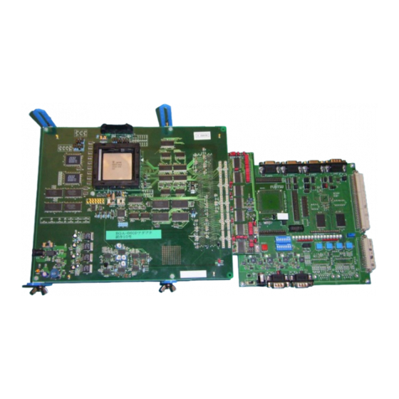
Page 13: Connecting The Adapter Board To The Sk-91F467D-208Pfv
3. Connect the probe cable PB-91467D-208PFV to the SK-91F467D-208PFV and tighten the screw. The same procedure applies for the probe cable PB-91467D-LS-208PFV. Figure 7 shows the connected boards. Figure 7: Connected Adapter Board, Probe Cable and Evaluation Board © Fujitsu Microelectronics Europe GmbH - 13 - MCU-AN-391005-E-V17... -
Page 14: Power Up The Emulation System
2. Power on the MB91V460 Adapter Board (MB2198-300) ‘SW2 Power’. The ‘Power’ LED has to be illuminated. 3. Power on the evaluation board SK-91460-MAIN V1.2 Rule 3: To power down the emulation system, please follow the procedure reversely. MCU-AN-391005-E-V17 - 14 - © Fujitsu Microelectronics Europe GmbH... -
Page 15: Jumpers And Switches
(Debug Mode: Setup-> Dev. Environment-> Dev. Environment-> Execution-> watchdog) 4) SRAM_SFX: Depending on the connected emulation memory, the respective mode has to be selected. By default a SRAM is connected. © Fujitsu Microelectronics Europe GmbH - 15 - MCU-AN-391005-E-V17... -
Page 16: Emulator Interface
S15 = TRSTX–ICE S20 = BREAK-ON S16 = OFF–ICD3 S17 = OFF–ICD2 S18 = OFF–ICD1 S20 = OFF–ICD0 Note: 1) If the in-circuit-emulator (ICE) is used, the default settings have to be used. MCU-AN-391005-E-V17 - 16 - © Fujitsu Microelectronics Europe GmbH... -
Page 17: External Emulation Memory
8 MByte S11 MDENS0 4 MByte S12 MDENS2 2 MByte 1 MByte 512 kByte Prohibited Prohibited 0 Byte Default: S13 = D32-X MDENS0 = 0 MDENS1 = 0 MDENS2 = 0 © Fujitsu Microelectronics Europe GmbH - 17 - MCU-AN-391005-E-V17... -
Page 18: Clock Control
S24 = EML-X0A S25 = EML-X1A S30 = MCLKI-USER S31 = MCLKO-USER By default the clocks are provided from the adapter board. By default MCLKI and MCLKO are connected to the evaluation board. MCU-AN-391005-E-V17 - 18 - © Fujitsu Microelectronics Europe GmbH... -
Page 19: Power Settings
S29 = UVCC3H–UVCC3 S8 = VCC3 – C Note: 1) SHDNSEL: VCC3 or VCC5 can be supervised. If the selected voltage fails, the power supply of the evaluation chip will be cancelled. © Fujitsu Microelectronics Europe GmbH - 19 - MCU-AN-391005-E-V17... -
Page 20: Signal Routing
P24_3 is connected to CN2_B67 Default: S21 = PULLDOWN – P10_7 S32 = P224 – CN2_B68 S33 = P242 – CN3_A6 S34 = P225 – CN2_B67 S35 = P243 – CN3_A5 MCU-AN-391005-E-V17 - 20 - © Fujitsu Microelectronics Europe GmbH... -
Page 21: Default Jumper Settings
In Figure 10 the default jumper settings of the adapter board are marked. The resistor can be removed, beside of R71, R74 and R75. Figure 10: Default Jumper Settings of the Adapter Board © Fujitsu Microelectronics Europe GmbH - 21 - MCU-AN-391005-E-V17... -
Page 22: Jumpers Of The Evaluation Board Sk-91460-Main V1.2
By default, the I/O-ports are supplied by 5 V. Note: 1) The Jumper S28 of the adapter board selects UVCC3 or MCU_VCC (UVCC5) as power supply for the I/O-port. By default this Jumper selects MCU_VCC (UVCC5). MCU-AN-391005-E-V17 - 22 - © Fujitsu Microelectronics Europe GmbH... -
Page 23: Default Jumper Settings
In Figure 11 the default jumper settings are marked. For detailed information about the jumpers, please refer to the hardware manual of the evaluation board. Figure 11: Default Jumper Settings of the Evaluation Board SK-91460-MAIN © Fujitsu Microelectronics Europe GmbH - 23 - MCU-AN-391005-E-V17... -
Page 24: Default Jumper Settings Of The Evaluation Board Sk-91F467D-208Pfv
In the following figure the default jumper settings are marked. For detailed information about the jumpers, please refer to the user guide of the evaluation board. Figure 12: Default Jumper Settings of the Evaluation Board SK-91F467D-208PFV MCU-AN-391005-E-V17 - 24 - © Fujitsu Microelectronics Europe GmbH... -
Page 25: Default Jumpers Settings Of The Probe Cable Pb-91467D-208Pfv
In the following figure the default jumper settings are marked. For detailed information about the jumpers, please refer to the user guide of the evaluation board. Figure 13: Default Jumper Settings of the Probe Cable PB-91467D-208PFV © Fujitsu Microelectronics Europe GmbH - 25 - MCU-AN-391005-E-V17... -
Page 26: Default Jumpers Settings Of The Probe Cable Pb-91467D-Ls-208Pfv
In the following figure the default jumper settings are marked. For detailed information about the jumpers, please refer to the user guide of the evaluation board. Figure 14: Default Jumper Settings of the Probe Cable PB-91467D-LS-208PFV MCU-AN-391005-E-V17 - 26 - © Fujitsu Microelectronics Europe GmbH... -
Page 27: Softune Workbench Getting Started
“led”. Save and close the file. Attention: If you use MS Word, please be sure to save the file as a normal text file, not as a word document! © Fujitsu Microelectronics Europe GmbH - 27 - MCU-AN-391005-E-V17... -
Page 28: Opening The Softune Workbench
Installation Guide App. Note. Choose the Menu File/Open. The following pop up window will occur: Figure 16: Open a Workspace Click “OK” for “Workspace/Project file”, and then browse to the file “Led.wsp”. Open it. MCU-AN-391005-E-V17 - 28 - © Fujitsu Microelectronics Europe GmbH... - Page 29 “Main.c”. It will look like this: Figure 17: The MAIN.C Code of the Template The code only contains the chip specific header inclusion and in the main routine a frame for the interrupt initialisation. © Fujitsu Microelectronics Europe GmbH - 29 - MCU-AN-391005-E-V17...
-
Page 30: Entering The Code
By double clicking on the correct connection type of the Debug dependency in the Project window (*.sup-files), your PC will connect to the MB2198-01 Emulator and the Softune Workbench will enter the Debugging Mode. After a successful connection, the Softune Workbench will look like this: MCU-AN-391005-E-V17 - 30 - © Fujitsu Microelectronics Europe GmbH... -
Page 31: Executing The Program
Note, that in the next start of the Workbench, your new LED-Project will occur in the menu list File/Recent Workspace File. By simply clicking to “Led.wsp”, the whole project will open again. © Fujitsu Microelectronics Europe GmbH - 31 - MCU-AN-391005-E-V17... -
Page 32: Setup / Change Connection Pc - Emulation System
2. After the PC is booted, power up the emulator. Windows will register a new hardware component and will start the hardware wizard. Select the option ‘No, not this time’ to search the drivers manually and press ‘Next’. MCU-AN-391005-E-V17 - 32 - © Fujitsu Microelectronics Europe GmbH... - Page 33 Figure 20: Installing the USB-driver II 4. Include the subfolder ‘Drivers’ of the unpacked the softune propack 911s Rev 60006, e. g. ‘c:\temp\rev600006\Drivers’ in the search. Press ‘Next’ to install the drivers. © Fujitsu Microelectronics Europe GmbH - 33 - MCU-AN-391005-E-V17...
-
Page 34: Setup Lan
The emulator MB2198-01 is provided with a local area network port that can be used to program and debug a device over a network connection. No additional hardware connection except the LAN connection itself is required for this purpose Using the Fujitsu LAN-remote controlled debug facility, MCU-AN-391005-E-V17 - 34 -... -
Page 35: Configuring The Lan Adapter
Getting Started Chapter 7 Setup / Change Connection PC – Emulation System • A Fujitsu support engineer can easily help solving a concrete problem by debugging your application out of a Fujitsu support centre. • You can control the emulator from different locations without having to move your hardware installation from one place to another. -
Page 36: Configuring Operating System "Windows
(Note: if 5001/tcp is already contained in the file services, use an unused number beginning with 5002 or greater, e.g. fjicesv 5002/tcp. In that case also the emulator address given by the program „LAN address“(see above) has to be changed! MCU-AN-391005-E-V17 - 36 - © Fujitsu Microelectronics Europe GmbH... - Page 37 IP-number with a simple name within your local network. Of course, you can define different names for the same IP-Address, as shown below. Edit file lmhosts and add the following line: © Fujitsu Microelectronics Europe GmbH - 37 - MCU-AN-391005-E-V17...
-
Page 38: Checking The Network-Connection
If this will work, then check settings (nickname and IP-address) within Imhosts and Hosts. If neither nickname (my_emulator) nor IP-address will work, check settings done by the program LAN-address and check the file Services. MCU-AN-391005-E-V17 - 38 - © Fujitsu Microelectronics Europe GmbH... - Page 39 PC a „crossed network cable“is necessary. Good answer: Emulator/LAN-adapter replies with time-values: Figure 27: Testing the IP-Connection to the Emulator I „Failed“-answer: Emulator/LAN-adapter replies with timeout message: Figure 28: Testing the IP-Connection to the Emulator II © Fujitsu Microelectronics Europe GmbH - 39 - MCU-AN-391005-E-V17...
-
Page 40: Softune Workbench
IP-address of the emulator, set by the program „LAN- Address“, can be used. Nickname or IP address Figure 29: Changing the IP-Address of the Host in the Softune Workbench MCU-AN-391005-E-V17 - 40 - © Fujitsu Microelectronics Europe GmbH... -
Page 41: Appendix
Figure 23: Testing the IP-Connection to the Emulator I............39 Figure 24: Testing the IP-Connection to the Emulator II............39 Figure 25: Changing the IP-Address of the Host in the Softune Workbench ......40 © Fujitsu Microelectronics Europe GmbH - 41 - MCU-AN-391005-E-V17...
Need help?
Do you have a question about the MB91460 and is the answer not in the manual?
Questions and answers