Table of Contents
Advertisement
Quick Links
Advertisement
Table of Contents

Related Manuals for MICRO-EPSILON colorCONTROL MFA-5


Summary of Contents for MICRO-EPSILON colorCONTROL MFA-5
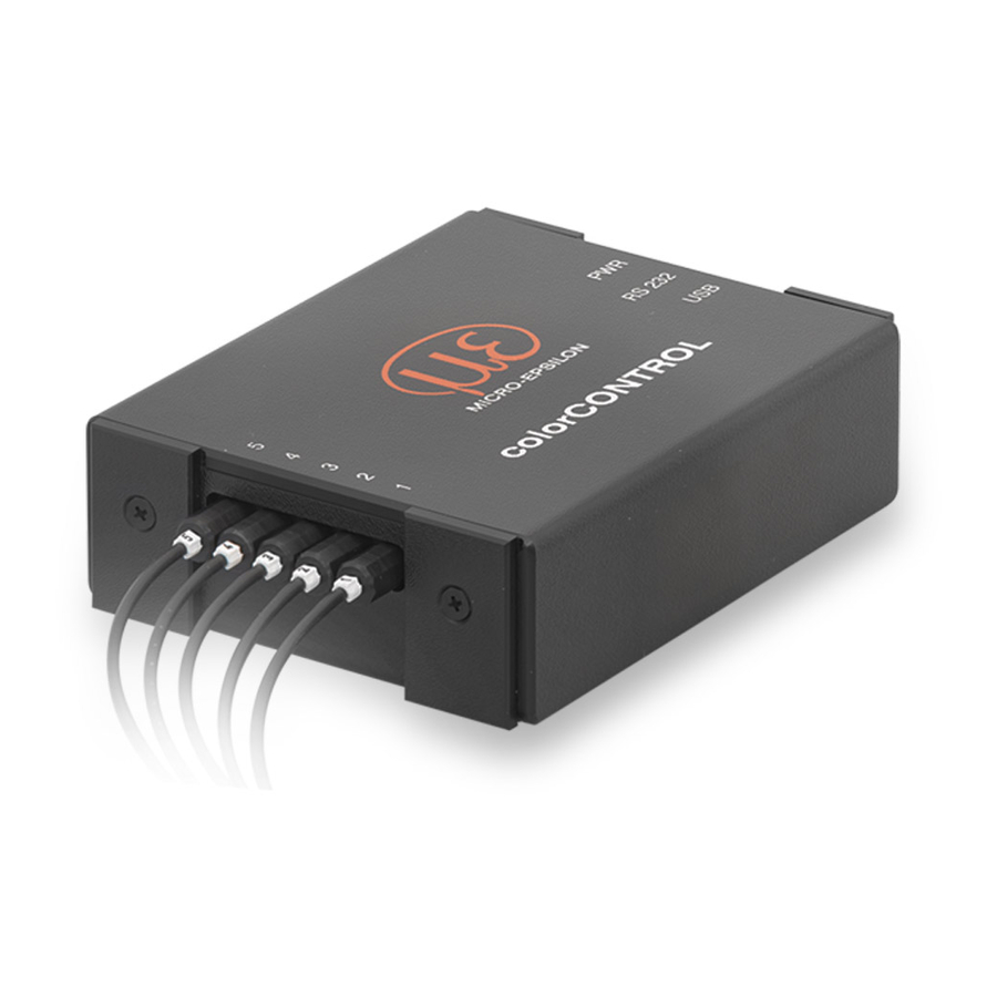
- Page 1 Instruction Manual colorCONTROL MFA-5...
- Page 2 Sensor system for LED tests of function, color and intensity MICRO-EPSILON Eltrotec GmbH Manfred-Wörner-Straße 101 73037 Göppingen / Germany Tel. +49 (0) 7161 / 98872-300 Fax +49 (0) 7161 / 98872-303 e-mail eltrotec@micro-epsilon.de www.micro-epsilon.com Certified according to DIN EN ISO 9001: 2008...
-
Page 3: Table Of Contents
Technical Data ............................... 10 Delivery ........................... 11 Unpacking ..............................11 Storage ................................11 Installation ..........................12 Installation of the colorCONTROL MFA-5 ...................... 12 Mounting the Optical Fiber ..........................13 4.2.1 Features ............................13 4.2.2 Installation with Threaded Ferrules ....................14 4.2.3... - Page 4 Read Ranges of the Intensities for all Optical Fibers ..........55 6.2.3.9 Read User-defined Test Time ..................55 6.2.3.10 Read Offset of the x Chromaticity Coordinate ............56 6.2.3.11 Read Offset of the y Chromaticity Coordinate ............56 6.2.3.12 Read Distance between LED and colorCONTROL MFA-5 ......... 57 colorCONTROL MFA-5...
- Page 5 6.2.4.8 Set colorCONTROL MFA-5 to Default Values ............. 60 6.2.5 Hardware and Software ........................ 61 6.2.5.1 Read Serial Number of the colorCONTROL MFA-5 ............ 61 6.2.5.2 Read Firmware Version Number ................. 61 6.2.5.3 Read Hardware Version Number ................61 6.2.6 Baud Rate .............................
- Page 6 A 3.13 Can Several LEDs be Tested Simultaneously? ..................... 70 A 3.14 Which Output Formats can be Provided by the colorCONTROL MFA-5? ............ 70 A 3.15 How can the colorCONTROL MFA-5 be Connected to a PC? ..............70 A 3.16 What Distance should the Optical Fiber be from the LED to be Tested? .............
-
Page 7: Safety
Never kink the fiber optics and do not bend tightly. > Damage to or destruction of the fiber optics; partial failure of the sensor. Protect the ends of the fiber optics from dirt and contamination (use protective caps). > Failure of the testing device colorCONTROL MFA-5 Page 7... -
Page 8: Notes On Ce Identification
Proper Use The colorCONTROL MFA-5 is a testing system that uses an opto-electronic sensor in combination with a fiber optic cable (POF 2.2 mm) to test intensity, color and function of illuminants such as LEDs and incandescent bulbs. -
Page 9: Proper Environment
-20 ... +80 °C (-4 up to +176 °F) - Storage temperature: -20 ... +80 °C (-4 up to +176 °F) - Humidity: 20 - 80 % (non-condensing) - Ambient pressure: Atmospheric pressure - EMC: Acc. to EN 61000-6-3: 2011-09 EN 61000-6-2: 2006-03 colorCONTROL MFA-5 Page 9... -
Page 10: Functional Principle, Technical Data
Functional Principle, Technical Data Functional Principle, Technical Data Short Description The colorCONTROL MFA-5 is a testing system that measures both color and function as well as intensity of light emitting diodes (LEDs) quickly and automatically. Technical Data MFA-5/ -M Model... -
Page 11: Delivery
2) Before version 2.0.0.1: Aluminum 3) POF = Polymer Optical Fiber Delivery Unpacking colorCONTROL MFA-5 sensor with M9 plug connector optical fibers POF-2.2; 0.5 m length (ø 2.2 mm) instruction manual and software CD For optional accessories, see Chap. Check for completeness and shipping damage immediately after unpacking. -
Page 12: Installation
Installation of the colorCONTROL MFA-5 Mount the sensor in your test set-up using four M3 screws. The colorCONTROL MFA-5 can be mounted both on the top side as well as on the bottom side of your test set-up. Ensure careful handling during installation and operation. -
Page 13: Mounting The Optical Fiber
Installation 120 (4.72) (1.38) 130 (5.12) Fig. 2 Dimensional drawing for the colorCONTROL MFA-5, Abmessungen in mm, not to scale Mounting the Optical Fiber 4.2.1 Features - Minimum bending radius 25 mm - Digital opening 0.5 - Angle of incidence approx. 60 degrees - Damping for 650 nm - 0.18 dB/m (approx. -
Page 14: Installation With Threaded Ferrules
- Mounting with a clamping collet for thin optical fibers 4.2.2 Installation with Threaded Ferrules Mount the optical fiber using a threaded ferrule M4, threaded ferrule M4 + 6 mm attachment lens or a threaded ferrule M4 + 3 mm converging lens. colorCONTROL MFA-5 Page 14... -
Page 15: Installation With A Guide Sleeve 1 Mm
Optical fibers smaller than ø 1 mm can also be fixed with a clamping collet E39-F9 in addition to the guide sleeves 1 mm. Fixing with a silicone adhesive is not necessary thereby. The optical fiber is fixed; however, it can be replaced if required. Fig. 7 Clamping collet E39-F9 colorCONTROL MFA-5 Page 15... -
Page 16: Shortening The Optical Fiber
Installation 4.2.5 Shortening the Optical Fiber The optical fibers of the colorCONTROL MFA-5 are shipped with a length of approximately 600 mm as stan- dard. Shorten the optical fiber to the optimum length. NOTICE > This prevents damage to the optical fiber. -
Page 17: Individual Colorcontrol Mfa-5 Sensor
4.3.1 Individual colorCONTROL MFA-5 Sensor The colorCONTROL MFA-5 can be operated both via an RS232 as well as via a USB port. In USB operation, the power for a sensor is supplied via the USB interface. In RS232 operation, an external power supply of 10 - 30 VDC, approximately 80 mA (max. 320 mA) must be used. - Page 18 Fig. 12 Female connector M5 Binder 707 Power supply Description Wire color +24 VDC white brown The power supply, USB and RS232 cables can be Fig. 13 Male connector M9 Binder 712 ordered as accessories, see Chap. colorCONTROL MFA-5 Page 18...
-
Page 19: Synchronization
4.3.2 Synchronization The colorCONTROL MFA-5 can be connected using the colorCONTROL MFA-5-M expansion module to maxi- mum 4 colorCONTROL MFAs and thus test 20 LEDs. The colorCONTROL MFA-5s are connected to each other and plated through using appropriate assembly kits, see Chap. - Page 20 Installation Assembly kit MFA-10 colorCONTROL MFA-5-M colorCONTROL MFA-5 Fig. 15 Combined system of 1 colorCONTROL MFA-5 with 1 colorCONTROL-MFA-5-M and assembly kit MFA-10/front side Assembly kit MFA-10 colorCONTROL MFA-5-M colorCONTROL MFA-5 Fig. 16 Combined system of 1 colorCONTROL MFA-5 with 1 colorCONTROL-MFA-5-M and assembly kit...
-
Page 21: Operation
Operation Operation Commissioning Make the following settings after the MICRO-EPSILON LED Check software has been installed and the color- CONTROL MFA-5 has been connected: 5.1.1 Configuration: Port (Interface) The USB port is configured as virtual COM port and is designated as Com5, Com6 etc. - Page 22 Operation The colorCONTROL MFA-5 test program is a graphical tool which can send commands to and receive results from the colorCONTROL MFA-5. The LEDs are tested individually. The results are saved in a file (e.g. TestReport.txt). The program specifies the optimum setting for the LED to be tested. For operation of the colorCONTROL MFA-5 program, see Chap.
-
Page 23: Color Chip Of The Colorcontrol Mfa-5
Pin no. 6 side Pin no. 6 side Fig. 17 Color chip of the colorCONTROL MFA-5 with High and Low Sensitivity Mode In addition to both the High Sensitivity Mode and Low Sensitivity Mode, the light intensity can also be influ- enced via the measuring time of 1 ms to 10000 ms. -
Page 24: Setting An Offset For The Calculation Of The X Any Y Chromaticity Coordinates
This can be done during the installation of the firmware using a non-volatile stored offset. 2. It is also possible to integrate the colorCONTROL MFA-5 in an existing test system via initialisation of the COM port and a command set, see Chap. - Page 25 Clear the checkbox Don‘t allow any changes to the XY offset values. Open the Test pop-up menu and then Measurement settings All adjustment parameters of the individual checkpoints of the colorCONTROL MFA-5 are displayed. Now select the required sensor / required checkpoint by double clicking on the line.
- Page 26 Operation Test - single color chip Fig. 18 Settings for test sensitivity colorCONTROL MFA-5 Page 26...
-
Page 27: Software Description Of Micro-Epsilon Led-Check
Software Description of MICRO-EPSILON LED-Check 5.2.1 User interface, Settings After the MICRO-EPSILON LED Check software has been started, the start screen is displayed, see Fig. All required functions and control elements are reached using this start screen. Fig. 19 Start screen... - Page 28 The respective test values for the individual color spaces can be found in the right- hand half of the Test Result window. Communication - The colorCONTROL MFA-5 is connected to or disconnected from the LED Check software here. - The configuration settings of the colorCONTROL MFA-5 are opened here using the menu, see Chap.
- Page 29 Fig. 20 Start screen extract Connect Button The colorCONTROL MFA-5 is connected to the software after pressing the Con- nect button. In doing so, the button label changes to Disconnect. The color- CONTROL MFA-5 is disconnected after pressing the button again.
- Page 30 MICRO-EPSILON LED Check firmware used and the number of connected colorCONTROL MFA-5 sensors. It also informs the user about any occurring errors. All light parameters tested and calculated by the colorCONTROL MFA-5 are displayed to the user in the win- dow Test Results, see Fig.
- Page 31 - Next to this on the right are the HSI values (Hue - Saturation - Intensity). - On the far right, the CIE 1931 color space with the x and y chromaticity coordinates. The Correlated Color Temperature (CCT) is also displayed on the bottom right. colorCONTROL MFA-5 Page 31...
-
Page 32: Configuration
Operation 5.2.2 Configuration Before you can perform any test with the colorCONTROL MFA-5, you must first make the following configuration settings, see Fig. Fig. 22 Configuration window Using this pull-down menu, you select the COM port which is assigned to the Serial Port colorCONTROL MFA-5 by Windows. - Page 33 The log file is defined in this window. This section is not important for usual use. It Log file window is only needed for error analysis for the MICRO-EPSILON LED Check program. The storage locations for the test report file and sensor settings file are defined Storage window here.
-
Page 34: Color Test Using The Function Elements Of The Start Screen
In the case of an application with several LEDs with the same light intensity, it is sufficient to determine the setting of the color chip range for one LED in this way. Afterwards, this setting can be transferred to the other checkpoints / color chips using the Measurements window, see Chap. 5.2.4. colorCONTROL MFA-5 Page 34... - Page 35 Operation Fig. 23 Sensor values and intensity section colorCONTROL MFA-5 Page 35...
-
Page 36: Color Test And Comparison Of Several Leds
In the following example, see Fig. 24, 5 checkpoints / color chips have been set using the main screen. Thereby, the checkpoint 4 (color chip 4) has a permanently stored offset. Fig. 24 List of settings window colorCONTROL MFA-5 Page 36... - Page 37 Perform Measurement button, the program compares the test values with the reference values, see Fig. 26. If any difference occurs in doing so, this is displayed in red. Archive the test result using the Save Test Report button. colorCONTROL MFA-5 Page 37...
- Page 38 Operation Fig. 26 Comparison test colorCONTROL MFA-5 Page 38...
-
Page 39: Changing Tolerances, Checkpoint Settings And An Offset
Now activate the checkbox in the window Settings for sensor. Now input the x and y offsets and confirm with OK. Changes made here will not be applied until the next test using the Measurements window. Fig. 27 Settings for sensor window colorCONTROL MFA-5 Page 39... -
Page 40: Test And Comparison Of Several Leds With The Same Light Intensity
OK. Select the checkpoint whose parameters should be applied. Press the change all settings button. The parameters are applied to the other checkpoint lines. The changes become effective after performing a test using the Measurement window. colorCONTROL MFA-5 Page 40... -
Page 41: Reset Of Offset Settings To The Factory Settings
Use the Reset Board command on the Test pop-up menu to restore the factory settings of the color- CONTROL MFA-5. Now disconnect the colorCONTROL MFA-5 using the Disconnect button. Restart the software to apply the condition as delivered. colorCONTROL MFA-5... -
Page 42: Use Of The Terminal Mode
You can test the ASCII communication commands and retrieval of the color values using this terminal mode. This is used for simplified integration of the colorCONTROL MFA-5 in your test system. The detailed com- mand overview can be found, see Chap. -
Page 43: Commands
Read user-defined test time Chap. 6.2.3.10 getxoffset# b Read offset of the x chromaticity coordinate Chap. 6.2.3.11 getyoffset# b Read offset of the y chromaticity coordinate Read distance between LED and colorCONTROL Chap. 6.2.3.12 getdistance# b MFA-5 colorCONTROL MFA-5 Page 43... - Page 44 Set distance between LED and optical fiber Chap. 6.2.4.8 setdefault b Set colorCONTROL MFA-5 to default values Hardware and software Chap. 6.2.5.1 getserial Read serial number of the colorCONTROL MFA-5 Chap. 6.2.5.2 getversion Read firmware version number Chap. 6.2.5.3 gethw Read hardware version number Baud rate Chap.
-
Page 45: Commands
This command is used for checking the connection between the test system / PC and the colorCONTROL MFA-5. If only one colorCONTROL MFA-5 sensor is connected to the sensor and the connection is present, the "OK" response is received. If several colorCONTROL MFA-5 sensors are connected, the number of the colorCONTROL MFA-5 sensors is also indicated, e.g. -
Page 46: Check
This command tells the colorCONTROL MFA-5 to check and save the colors and intensity of all connected LEDs at the same time. The test time and the color chip sensitivity range (9x9; 3x3) can be set before the actual test using the com- mand setcaptimexyz b, see Chap. -
Page 47: Manual Check
For very bright LEDs, the Sensor Low setting is selected (only 3x3 segments of the color chip are used) and the test time is reduced accordingly (e.g. 10 or 2 ms). Board = colorCONTROL MFA-5 Channel = checkpoint colorCONTROL MFA-5... - Page 48 Commands Fig. 29 Color chip of the colorCONTROL MFA-5 test system A color chip consists of 9x9 = 81 segments for the colors red, green and blue. All segments are used and a long exposure time is selected for dark LEDs.
-
Page 49: General Check Of Pulsed Leds
PWM LED = Pulse Width Modulated LED This command tells the colorCONTROL MFA-5 to check and save the colors and intensity of all connected LEDs. Thereby, a default setting is used which is sufficient for most LEDs. -
Page 50: Manual Check Of Pulsed Leds
The first two factors refer to the average factor of minimum 5 and maximum 80 test processes. z refers to the channel and b identifies the colorCONTROL MFA-5 used. The Average Factor is divided in 15 ranges, factor 2 relates to 15 test processes. -
Page 51: Output
= 0 ... 99999 0060 2301 0185 b not specified 06383 In the specified case, the data of LED 3 are read from the colorCONTROL MFA-5 / 5 or LED numbered 23. The values are for 0060 Green 2301... -
Page 52: Read Saved Rgb Color Components In Percent From The Memory
# = channel number 1 ... 5 or # = 1 ... 495 for Output format: # = 1 ... 495 max. 99 boards, 123.47 089 04383 b not specified Board = colorCONTROL MFA-5 Channel = checkpoint colorCONTROL MFA-5 Page 52... -
Page 53: Read Saved Xy Chromaticity Values From The Memory
00000 = calculation temperature not possible # = b values see # = channel number Output format getrgbi 1 ... 5 b or °Kelvin: 05679.9 # = 1 ... 495 Board = colorCONTROL MFA-5 Channel = checkpoint colorCONTROL MFA-5 Page 53... -
Page 54: Read Value For Intensity
Read saved gain getintgain1 Standard = 100 % # b values, see # = channel number Output format Chapter 6.2.3.1 1 ... 5 b or (getrgb) # = 1 ... 495 Channel = checkpoint colorCONTROL MFA-5 Page 54... -
Page 55: Read Ranges Of The Intensities For All Optical Fibers
Description Received Example Note getusertime b Read user-defined test xxxxx getusertime Time in ms, b = time (of board 1) board. If specified, otherwise board 1 Output format 01000 Board = colorCONTROL MFA-5 Channel = checkpoint colorCONTROL MFA-5 Page 55... -
Page 56: 6.2.3.10 Read Offset Of The X Chromaticity Coordinate
3 board 1 ... 5 # = 1 ... 495 for max. 99 boards, Output format # 1 ... 495, b not specified. -0.0015 b = board Board = colorCONTROL MFA-5 Channel = checkpoint colorCONTROL MFA-5 Page 56... -
Page 57: Read Distance Between Led And Colorcontrol Mfa-5
Commands 6.2.3.12 Read Distance between LED and colorCONTROL MFA-5 getdistance## b Command Description Received Example Note getdistance## b Fetch saved distance xxx.x getdistance4 # = 1 ...5, if b = # = channel number value in mm board 1 ... 5 # = 1 ... -
Page 58: Set The Average Factor Without Test
# = channel number setintgain23095 Set channel 23 to 95% 1 ... 5 b # = sensor or # = 1 ... 495 Output format: xxx = value, b = board Board = colorCONTROL MFA-5 Channel = checkpoint colorCONTROL MFA-5 Page 58... -
Page 59: Set User-Defined Test Times
Set channel 1 y # = channel number offset value Output format: OK offset to -0.050 1..5 b # = sensor, or # = 1..495 xxx = value b = board Board = colorCONTROL MFA-5 Channel = checkpoint colorCONTROL MFA-5 Page 59... -
Page 60: Set Distance Between Led And Optical Fiber
= 2 mm Output format: OK = sensor, or # = 1..495 Range: 000.0 - xxx.x = value, 999.9 mm b = board 6.2.4.8 Set colorCONTROL MFA-5 to Default Values setdefault b Command Description Received Example Note setdefault b Set default values... -
Page 61: Hardware And Software
Commands 6.2.5 Hardware and Software 6.2.5.1 Read Serial Number of the colorCONTROL MFA-5 getserial Command Description Received Example Note getserial Read serial number xxxx getserial 4 positions of the colorCONTROL MFA-5 Output format: 75A6 6.2.5.2 Read Firmware Version Number getversion... -
Page 62: Baud Rate
Every received character string is terminated with CR A space character must be sent between the command and the number of the colorCONTROL MFA-5. If you use several colorCONTROL MFA-5, the command testcon must be sent before the test value recording, see Chap. -
Page 63: Instructions For Operation
The warranty period lasts 12 months following the day of shipment. Defective parts, except wear parts, will be repaired or replaced free of charge within this period if you return the device free of cost to MICRO-EPSILON Eltrotec. This warranty does not apply to damage resulting from abuse of the equipment and devices, from forceful handling or installation of the devices or from repair or modifications performed by third parties. -
Page 64: Service And Repair
Disconnect the power supply cable and all output cables from the sensor. Disconnect the fiber optics from the sensor. colorCONTROL MFA-5 is produced according to the 2011/65/EU RoHS directive. The disposal is done ac- cording to the legal regulations (see directive 2002/96/EC). -
Page 65: Appendix
Appendix| Accessories Appendix Accessories Designation Description Order number colorCONTROL MFA-5-M Expansion module (for another 5 Order no. 11094051 checkpoints) CAB-M9-2P-Bu-ge; 2m-PUR; open Power cable; length 2 m Order no. 11294205 CAB-M9-2P-Bu-ge; 5m-PUR; open Power cable; length 5 m Order no. 11294206 CAB-M9-4P-St-ge;... -
Page 66: Factory Settings
Modules Reducer adapter 2.2/1 mm POF for use with POF 1 mm Order no. 11253959 Guide sleeve 1 mm for POF 1 mm Order no. 11253906 Clamping collet Clamping collet E39-F9 Factory Settings Baud rate 115200 colorCONTROL MFA-5 Page 66... -
Page 67: A 3 Frequently Asked Questions About The Colorcontrol Mfa-5
Can bar graph displays be tested? Chap. A 3.13 Can several LEDs be tested simultaneously? Chap. A 3.14 Which output formats can be provided by the colorCONTROL MFA-5? Chap. A 3.15 How can the colorCONTROL MFA-5 be connected to a PC? Chap. A 3.16 What distance should the optical fiber be from the LED to be tested? Chap. -
Page 68: A 3.2 Which Types Of Leds And Colors Can Be Tested
Which Types of LEDs and Colors can be Tested? The colorCONTROL MFA-5 records the complete spectrum of visible light (390 - 780 mm) from light emit- ting diodes (LEDs). All sizes and forms and very bright or very dark LEDs can be tested. As well as standard LEDs, bi-color and tri-color LED displays and luminous bar displays can also be tested. -
Page 69: A 3.6 How Precise Is The Colorcontrol Mfa-5
Yes, provided you treat each segment as an individual LED and mount an optical fiber over each segment. The displayed numerals from 0 to 9 can thus also be tested. At least 7 checkpoints are needed for this (1x colorCONTROL MFA-5 + 1x colorCONTROL MFA-5-M + as- sembly kit MFA-10). -
Page 70: A 3.12 Can Bar Graph Displays Be Tested
Which Output Formats can be Provided by the colorCONTROL MFA-5? The colorCONTROL MFA-5 can provide the data both via a USB or RS232 interface. The results can be out- put both as RGB, HSI or CIE values as well as the color temperature in Kelvin. -
Page 71: A 3.19 How High Is The Power Requirement
A 3.19 How High is the Power Requirement? The colorCONTROL MFA-5 with 5 channels has a current consumption of approx. 80 mA, for 24 V (5 V with board version). The colorCONTROL MFA-5 can be operated both via an RS232 as well as via a USB port. - Page 72 Appendix| Software Description RS232 Open.vi Enables the preset of the port using which the colorCONTROL MFA-5 RS232 communicates. The associated COM port can be selected for the input OPEN using VISA resource name. The current baud rate setting is 115200 and applies for all sensors from firmware version 1005.
- Page 73 Appendix| Software Description RS232 CaptureStan- The colorCONTROL MFA-5 is told to capture and save the colors and the RS232 dard.vi intensity of all connected LEDs simultaneously. CAPTURE Response "OK" RS232 CaptureMan- Using the color chip range, the image range of the color chip can be set RS232 ual.vi...
- Page 74 RS232 GetRGBi.vi Fetch saved values for RGB and intensity. RS232 RGBI RGBI RS232 GetXY.vi Fetch saved value for XY chromaticity. RS232 data XY Chromacity RS232 GetHSI.vi Fetch saved values for HUE, saturation and intensity. RS232 data HSI colorCONTROL MFA-5 Page 74...
-
Page 75: Strict Type Def
(see RS232 CaptureManual.vi) Type Time range selection.ctl. Enum from 10 elements Test time preselection: from 2 to 600 ms Type Measurement selection.ctl. Enum from 4 elements Test type preselection: XY data RGBI HSI color temperature colorCONTROL MFA-5 Page 75... - Page 76 Currently, up to 20 sensors can be ad- dressed. Up to 99 sensors can be implemented. Type Number of LED.ctl Ring from 5 elements Selection of the checkpoints of a selected sensor. Up to 5 checkpoints per sensor can be ad- dressed. colorCONTROL MFA-5 Page 76...
-
Page 77: A 4.4 Test.vi
Appendix| Software Description A 4.4 Test.vi All relevant Sub.vis are integrated in Test.vi. All connected sensors and 5 checkpoints each are passed through using a For loop. colorCONTROL MFA-5 Page 77... - Page 80 X9751296-A051059SWE MICRO-EPSILON Eltrotec GmbH Manfred-Wörner-Straße 101 · 73037 Göppingen / Germany MICRO-EPSILON Eltrotec Tel. +49 (0) 7161 / 98872-300 · Fax +49 (0) 7161 / 98872-303 *X9751296-A05* eltrotec@micro-epsilon.de · www.micro-epsilon.com...
Need help?
Do you have a question about the colorCONTROL MFA-5 and is the answer not in the manual?
Questions and answers