MICRO-EPSILON induSENSOR MSC7401 Operating Instructions Manual
Hide thumbs
Also See for induSENSOR MSC7401:
- Operating instructions manual (58 pages) ,
- Operating instructions manual (102 pages)

Related Manuals for MICRO-EPSILON induSENSOR MSC7401


Summary of Contents for MICRO-EPSILON induSENSOR MSC7401
- Page 1 Operating Instructions induSENSOR, MSC7401 / 7802 / 7602 MSC7401 MSC7602 MSC7401(0x0) MSC7802 MSC7802(0x0)
- Page 2 Miniature sensor controller for inductive displacement sensors MICRO-EPSILON MESSTECHNIK GmbH & Co. KG Koenigbacher Str. 15 94496 Ortenburg / Germany Phone +49 (0) 8542 / 168-0 Fax +49 (0) 8542 / 168-90 e-mail info@micro-epsilon.com www.micro-epsilon.com...
-
Page 3: Table Of Contents
Contents Safety ............................7 Symbols Used ..............................7 Warnings ................................7 Notes on CE Marking ............................8 Intended Use ..............................8 Proper Environment ............................9 Functional Principle, Technical Data ..................10 Functional Principle ............................10 Structure ................................ 11 Technical Data .............................. 12 Delivery .......................... - Page 4 Operation ..........................42 Initial Operation .............................. 43 Control and Display Elements ........................45 Setting ................................46 5.3.1 Automatic Sensor Recognition..................... 47 5.3.2 Signal ............................47 5.3.3 Sensor Parameters ........................48 5.3.4 Adjustment ............................ 49 Menu Structure .............................. 50 5.4.1 2-Point Adjustment ........................53 5.4.2 Zero-Point Search .........................
- Page 5 Appendix Optional Accessories ......................66 Factory Settings ........................68 Software ..........................69 A 3.1 Controller Search ............................69 A 3.2 Measurement Menu ............................72 A 3.2.1 Main View ............................. 73 A 3.2.2 Start / Stop ............................ 73 A 3.2.3 Signal Processing ......................... 74 A 3.2.4 CSV Output ...........................
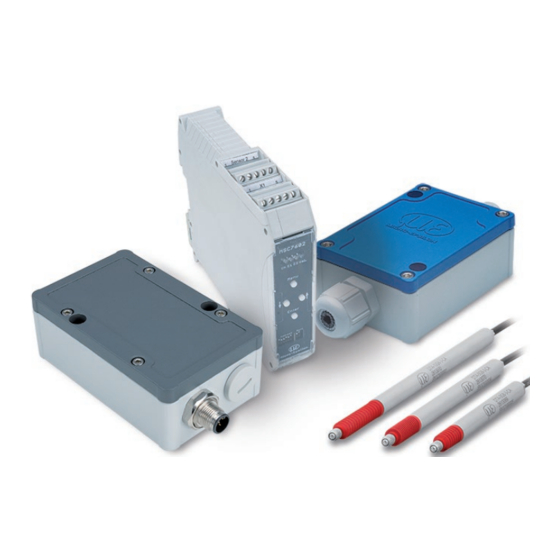
- Page 6 MSC7401 / 7802 / 7602 Miniature sensor controller for inductive displacement sensors...
-
Page 7: Safety
Safety Safety Sensor operation assumes knowledge of the operating instructions. Symbols Used The following symbols are used in these operating instructions: Indicates a hazardous situation which, if not avoided, may result in minor or moderate injury. Indicates a situation that may result in property damage if not avoided. Indicates a user action. -
Page 8: Notes On Ce Marking
The measuring system is designed for use in industrial environments and meets the requirements. Intended Use Das induSENSOR MSC7401 / 7802 / 7602 measuring system is designed for use in industrial environments. It is used to control inductive displacement sensors based on the LVDT principle (Linear Variable Differential Transformer) and for operation with LDR displacement sensors. -
Page 9: Proper Environment
Safety Proper Environment - Protection class: ƒ MSC7401 and 7802: IP 67 ƒ MSC7602: IP 20 - Temperature range: ƒ Operation: -40 ... +85 °C (-40 ...185 °F) ƒ Storage: -40 ... +85 °C (-40 ...185 °F) - Humidity: 5 - 95 % (non-condensing) - Ambient pressure: Atmospheric pressure - Vibration/Shock:... -
Page 10: Functional Principle, Technical Data
Safety Functional Principle, Technical Data Functional Principle The MSC 7401 / 7802 / 7602 series are single- and multi-channel miniature sensor controllers for the opera- tion of inductive displacement sensors based on the LVDT principle (full bridge) and for half-bridge sensors. An electronic oscillator supplies the primary coil with an alternating current of constant frequency and ampli- tude. -
Page 11: Structure
MICRO-EPSILON recommends the inductive displacement sensors and gauging sensors of the induSENSOR DTA and LDR series because they are optimally adjusted with the controller. -
Page 12: Technical Data
Functional Principle, Technical Data Technical Data Model MSC7401 MSC7802 MSC7602 Resolution 13 bits (0.012 % FSO) with 50 Hz (frequency response) DTA series 12 bits (0.024 % FSO) with 300 Hz (frequency response) 12 bits (0.024 % FSO) with 50 Hz (frequency response) LDR series 11 bits (0.048 % FSO) with 300 Hz (frequency response) Frequency response (-3 dB) - Page 13 Functional Principle, Technical Data Model MSC7401 MSC7802 MSC7602 ± 2 mm / 10 … 15.77 Hz in ± 1.5 mm / 5 … 57 Hz in 3 axes, 10 cycles each 3 axes, 10 cycles each Vibration (DIN-EN 60068-2-6) ± 20 g / 57 … 500 Hz in 3 axes, 10 cycles each ±...
-
Page 14: Delivery
Delivery Delivery Unpacking/Included in Delivery 1 Controller 1 Assembly instruction 2 Sleeve-shaped ferrites (with induSENSOR MSC7602 model) 2 Fastening clips for ferrites for M4 screw Carefully remove the components of the measuring system from the packaging and ensure that the goods are forwarded in such a way that no damage can occur. -
Page 15: Installation And Assembly
Installation and Assembly Installation and Assembly Precautions No sharp or heavy objects should be allowed to affect the sensor cable and the supply/output cable. > Damage to or destruction of the controller Check all plug-in connections for firm seating before starting operation. Ensure careful handling during installation and operation. - Page 16 Installation and Assembly 52 (2.04) (.47) (1.18) Power and signal connection: Sensor connection: Cable gland WS19 Cable gland WS15 Clamping range 4.5 mm ... 10 mm Clamping range 1 mm ... 5 mm 25.5 76 (2.99) 21.5 (1.0) (.85) Ø4.3 (.17 dia.) Ø7.5 (.29 dia.)
- Page 17 Installation and Assembly 52 (2.04) (.47) (1.18) Power and signal connection Sensor connection: M12x1 plug; 5-pole M9 5-pole socket Series 712 (Binder) 76 (2.99) 14.5 (.12) (.57) Ø4.3 (.17 dia.) Ø7.5 (.29 dia.) Fig. 3 Dimensions of MSC7401(010) controller, dimensions in mm (inches), not to scale MSC7401 / 7802 / 7602 Miniature sensor controller for inductive displacement sensors Page 17...
-
Page 18: Msc7802 Model
Installation and Assembly 4.2.2 MSC7802 Model Fasten the controller of series MSC7802 by means of two M4 screws, see Fig. The position of the mounting holes is shown in the drawing, see Fig. The tightening torque for the cover screws is 0.9 Nm. The maximum tightening torque for the SW15 (M12) cable gland is 1.5 Nm and for the SW19 (M16) cable gland is 3 Nm. - Page 19 Installation and Assembly 34.2 36.6 (1.35) (1.44) (1.50) Power and signal connection: Sensor connections: Cable gland WS19 Cable gland WS15 Clamping range 4.5 mm ... 10 mm Clamping range 1 mm ... 5 mm Ø7.5 (.29 dia.) Ø4.3 (.17 dia.) 105 (4.13) 25.5 21.5...
- Page 20 Installation and Assembly 36.6 34.2 (1.50) (1.44) (1.35) Power and signal connection: Sensor connections: M12x1 plug; 5-pole M9 5-pole socket Series 712 (Binder) Ø7.5 (.29 dia.) Ø4.3 (.17 dia.) 15.5 105 (4.13) (.61) (.16) 124.6 (4.90) Fig. 5 Dimensions of MSC7802(010) controller, dimensions in mm (inches), not to scale MSC7401 / 7802 / 7602 Miniature sensor controller for inductive displacement sensors Page 20...
-
Page 21: Msc7602 Model
Installation and Assembly 4.2.3 MSC7602 Model If required, install a DIN rail bus connector, e.g., ME22,5 TBUS 1,5/4P1S KMGY (Phoenix: 2201732), see 1, onto the DIN rail. If required, connect the mating plug, e.g., MCVR 1.5/5-ST-3.81 (Phoenix: 1827156), see A 1, with the bus connector. - Page 22 Installation and Assembly 22.6 29.2 (4.21) (.89) (1.15) 113.65 (4.47) Fig. 8 Dimensions of MSC7602 controller model, dimensions in mm (inches), not to scale MSC7401 / 7802 / 7602 Miniature sensor controller for inductive displacement sensors Page 22...
- Page 23 Installation and Assembly Installation with ferrite To stabilize the output signal against EMC interferences, you may in addition guide the sensor cables through a sleeve-shaped ferrite included in the scope of supply, see 3.1. This ferrite must be mounted as close as possible to the input terminals.
-
Page 24: Power Supply, Sensor And Signal Output Msc7401
Installation and Assembly Power Supply, Sensor and Signal Output MSC7401 The minimum bending radius of the PC7400-6/4 and PC5/5-IWT power supply and output cables (available as optional accessories, see A 1) is ten times the cable diameter. All of the connections for the power supply/ sensors/signal output are on the controller, see Fig. - Page 25 Fig. 13 Table of the pin assignment for the sensor at terminal block X2, full bridge 1) The colors and pins listed refer to the sensors from MICRO-EPSILON MESSTECHNIK GmbH & Co. KG. MSC7401 / 7802 / 7602 Miniature sensor controller for inductive displacement sensors...
- Page 26 The pin assignment for the terminal blocks can also be found in the graphic and the tables, see Fig. 16 1) The colors and pins listed refer to the sensors from MICRO-EPSILON & Co. KG. MSC7401 / 7802 / 7602 Miniature sensor controller for inductive displacement sensors...
-
Page 27: Power Supply And Signal
Installation and Assembly 4.3.1 Power Supply and Signal Fig. 16 Pin assignment for supply and signal on the terminal blocks X2, X3, X1 MSC7401 / 7802 / 7602 Miniature sensor controller for inductive displacement sensors Page 27... -
Page 28: Digital Interface
Installation and Assembly Pin assignment of supply Variant with Connector variant and analog output cable gland 5-pin M12x1 housing connector (A-coded; view on pin side) Assignment Pin X1 Color 5-pin Color (cable: PC7400-6/4) (cable: PC5/5-IWT) Analog output Yellow Black Supply voltage White Brown GND supply/signal ground 3... -
Page 29: Sensor
Installation and Assembly 4.3.3 Sensor The output signal increases, when the plunger is moved into the sensor. If the reverse effective direction is required (i.e. the signal becomes smaller when the plunger is inserted), replace the connections sec+ and sec-. Sensor pin Variant with Connector... - Page 30 Installation and Assembly Sensor pin assignment Variant with Connector (LDR) cable gland 5-pin housing socket M9 (Binder, series 712) View on pin side Assignment Pin X2 LDR-x-CA Cable 5-pin LVP-25-Z20-x C7210-x Shield Housing Secondary center tap Green Black Secondary + White Brown Secondary -...
-
Page 31: Power Supply, Sensor And Signal Output Msc7802
Installation and Assembly Power Supply, Sensor and Signal Output MSC7802 The minimum bending radius of the PC7400-6/4and PC5/5-IWT power supply and output cables (available as optional accessories), see A 1, is ten times the cable diameter. All of the connections for the power supply/ sensors/signal output are on the controller, see Fig. - Page 32 Fig. 24 Table of the pin assignment for the sensor at terminal block X2, full bridge 1) The colors and pins listed refer to the sensors from MICRO-EPSILON MESSTECHNIK GmbH & Co. KG. MSC7401 / 7802 / 7602 Miniature sensor controller for inductive displacement sensors...
- Page 33 The pin assignment for the terminal blocks can also be found in the graphic and the tables, see Fig. 27 1) The colors and pins listed refer to the sensors from MICRO-EPSILON MESSTECHNIK GmbH & Co. KG. MSC7401 / 7802 / 7602 Miniature sensor controller for inductive displacement sensors...
-
Page 34: Power Supply And Signal
Installation and Assembly 4.4.1 Power Supply and Signal D1 D2 D3 D4 Sensor 1 Chan. E1 E2 Value X2-1 X2-2 Menu Enter Sensor 2 Down Fig. 27 Pin assignment for power supply and signal on the terminal blocks X2, X3, X1 MSC7401 / 7802 / 7602 Miniature sensor controller for inductive displacement sensors Page 34... -
Page 35: Digital Interface
Installation and Assembly Pin assignment of supply and Variant with cable gland Connector variant analog output 5-pin M12x1 (A-coded); view on pin side Assignment Pin X1 Color 5-pin Color (cable: PC7400-6/4) (cable: PC5/5-IWT) Analog output for channel 2 Green White Analog output for channel 1 Yellow Black... -
Page 36: Sensor
Installation and Assembly 4.4.3 Sensor The output signal increases, when the plunger is moved into the sensor. If the reverse effective direction is required (i.e. the signal becomes smaller when the plunger is inserted), replace the connections sec+ and sec-. Pin assignment Variant with cable gland Connector... - Page 37 Installation and Assembly Pin assignment Variant with cable gland Connector Sensor 1 + 2 (LDR) Sensor 1 X2-1 X2-2 Sensor 2 5-pin housing socket M9 (Binder, series 712) View on pin side Assignment Pin X2-x LDR-x-CA Cable 5-pin LVP-25-Z20-x C7210-x Shield Housing Secondary center tap 2...
-
Page 38: Power Supply, Sensor And Signal Output Msc7602
Installation and Assembly Power Supply, Sensor and Signal Output MSC7602 The MSC7602 is designed for multi-channel operation. Therefore, power supply and RS485 must therefore be applied only to one controller and can then be transmitted to the adjacent controller via a DIN rail bus connector on the rear side. -
Page 39: Power Supply And Signal
Installation and Assembly 4.5.1 Power Supply and Signal Assignment Pin X1 Color (cable: PC7400-6/4) Supply voltage +24 V White GND supply/signal ground Brown Output signal 1 Yellow Output signal 2 Green 5 4 3 2 1 Cable shield sensor 2 (direct connection to DIN rail) X2-2 5 4 3 2 1... -
Page 40: Sensor
Installation and Assembly 4.5.2 Sensor 5 4 3 2 1 1 2 3 4 5 X2-2 X2-1 5 4 3 2 1 1 2 3 4 5 Fig. 38 Terminal block X2-2 Fig. 39 Terminal block X2-1 Assignment Pin X2-x DTA-x-CA-x DTA-x-CA-x DTA-xG8-x... -
Page 41: Digital Interface
Installation and Assembly Assignment Pin X2-x LDR-x-CA Cable LVP-25-Z20-x C7210-x Secondary center tap White White Secondary + Brown Black Secondary - Green Green Primary + Yellow Yellow Primary - Gray Gray Cable shield sensor 1 + 2, see X1 and X3 Fig. -
Page 42: Operation
Operation Operation Before starting the measurement or making settings, let the controller with connected sensor warm up for approx. 2 minutes while supply voltage is switched on. Observe the operating instructions of the sensors used. If a sensor is replaced, the channel must be re-parameterized and readjusted. The parameter setup of the controller may either be performed via keys on the controller or via the sensor- TOOL, see A 3. -
Page 43: Initial Operation
Then switch on the power supply. Set the controller to its basic setting, see 5.3. Down Menu Enter Fig. 43 Controller induSENSOR MSC7401 MSC7401 / 7802 / 7602 Miniature sensor controller for inductive displacement sensors Page 43... - Page 44 Operation D1 D2 D3 D4 Chan. E1 E2 Value Menu D1 D2 D3 D4 Sensor 1 Chan. E1 E2 Value X2-1 Enter X2-2 Address Sync Menu Enter Sensor 2 Down Fig. 44 Controller induSENSOR MSC7802 Fig. 45 Controller induSENSOR MSC7602 MSC7401 / 7802 / 7602 Miniature sensor controller for inductive displacement sensors Page 44...
-
Page 45: Control And Display Elements
Operation Control and Display Elements Button/LED Function Description Menu button Enter the menu level Enter button Confirmation buttons Parameter selection LED D1 / Ch Channel display The LED Channel indicates the Down Menu Enter current channel, with ... -
Page 46: Setting
Operation Setting The menu of the MSC7401 / 7802 / 7602 is designed for fast, mainly automated commissioning as well as for individual application-specific settings. It is divided into four function blocks, see Fig. 48. The 4 LEDs show the current position in the menu and the corresponding setting value at any time, 5.4. -
Page 47: Automatic Sensor Recognition
The first menu item is the automatic sensor recognition. LED D2 = red The automatic sensor recognition checks the connected sensor and determines the parameters for the com- mon MICRO-EPSILON sensors: - Sensor type (half bridge or full bridge (LVDT)) - Supply frequency and - Excitation voltage After the automatic sensor recognition has been completed, the LEDs confirm the status. -
Page 48: Sensor Parameters
Operation 5.3.3 Sensor Parameters LED D2 = red flashing With this function, you can set the parameters - sensor type, - supply frequency and - excitation voltage if the automatic recognition is not successful, or for special areas of use other settings may be necessary. These depend on the sensor model used. -
Page 49: Adjustment
Operation 5.3.4 Adjustment LED D2 = green At the menu item adjustment, you can use either a 2-point adjustment or a zero point search. In this menu, the controller can also be reset to the factory settings. 2-point Here you can set any 2 points within the measuring range and the corresponding signal values. -
Page 50: Menu Structure
Operation Menu Structure Legend of the menu structure LED orange LED orange flashing LED green LED green flashing LED red LED red flashing LED off Start of measuring range Mid of measuring range End of measuring range Fig. 52 Legend of the menu structure 1) For pages 51 to 58 MSC7401 / 7802 / 7602 Miniature sensor controller for inductive displacement sensors Page 50... - Page 51 Operation Next menu Channel Value 2-point Go to the adjustment modes adjustment 2-point adjustment, see Fig. 54 or zero-point search, see Fig. Adjustment Factory settings E1 level ENTER ENTER ENTER Zero-point search Successful Successful E1 level Automatic sensor reco- Failed Failed Sensor parameter MENU...
- Page 52 Operation Continuation of menu structure of page 51 Next menu Channel Value DTA (LVDT) Sensor Sensor type parameter ENTER ENTER 1 kHz 9 kHz 2 kHz 13 kHz Frequency 5 kHz 16 kHz 10 kHz 21 kHz 13 kHz 23 kHz ENTER 550 mV 350 mV...
-
Page 53: 2-Point Adjustment
Operation 5.4.1 2-Point Adjustment Channel Value Move the measuring object to position X , and change the output signal U with The LED color changes depending on the position Flashes orange of the measuring when the measu- object. ring object is in the electrical center of the sensor. -
Page 54: Zero-Point Search
Operation 5.4.2 Zero-Point Search Value Channel Set the output signal U LED off 6 VDC or 12 mA is preset. ENTER The LED flashes and color changes depending on the Lights orange when Move the measuring object to position X until the output signal the measuring object... -
Page 55: Example A: Sensor Parameter Adjustment: Dta-5G8, Channel 1
Operation 5.4.3 Example A: Sensor Parameter Adjustment: DTA-5G8, Channel 1 Press the MENU button for 3 sec. MENU After switching on, the sensor is automatically identified. If the recognition was successful, this color code is displayed and you can skip example A. Output situation: sensor is not automatically recognized. -
Page 56: Example B: Signal Output Adjustment: 2
Operation 5.4.4 Example B: Signal Output Adjustment: 2 ... 10 V, Channel 1 Press the MENU button for 3 seconds, if you are not yet in the menu. MENU Output situation: The sensor parameters are already set; depending on the approach, LED D4 is green or switched off. -
Page 57: Example C: Adjustment Via Zero Point Search, Channel 1
Operation 5.4.5 Example C: Adjustment via Zero Point Search, Channel 1 Set the sensor parameters according to example A and connect the output signal according to example B. Press the MENU button for 3 seconds, if you are not yet in the menu. MENU Output situation: The sensor parameters are already set;... -
Page 58: Example D: Adjustment Via 2-Point Adjustment, Channel 1
Operation 5.4.6 Example D: Adjustment via 2-Point Adjustment, Channel 1 Set the sensor parameters according to example A and connect the output signal according to example B. Press the MENU button for 3 seconds, if you are not yet in the menu. MENU Output situation: The sensor parameters are already set;... -
Page 59: Multi-Channel Operation
Operation Multi-Channel Operation When operating the MSC7401 / MSC7602 / MSC7802 models, multi-channel operation is possible. For multi-channel operation, a distance of at least 100 mm between the respective sensors is recom- mended. Recommended distance between the sensors ≥ 100 mm Fig. -
Page 60: Operation On The Rs485 Bus With Multiple Channels
Operation 5.5.1 Operation on the RS485 Bus with Multiple Channels The connection to the RS485 bus enables to directly read out the measurement values, see A The respective addresses can be individually set from 1 ... 126. Please avoid in each operating mode using the same addresses multiple times on the bus. >... - Page 61 Operation Address Switch setting Sensor 1 Sensor 2 Value binary 000000 000001 000010 000011 000100 111011 111100 111101 111110 111111 Fig. 60 Address assignment on the induSENSOR MSC7602 1) Factory settings 2) The address can be set using the sensorTOOL, see A Please note that the bus master requires an individual address.
-
Page 62: Synchronization And Installation Of Multiple Channels
Operation 5.5.2 Synchronization and Installation of Multiple Channels MSC7602 model If the minimum distance of ≥ 100 mm, see 5.3, is impossible, the MSC7602 model in addition offers the possibility to synchronize the supply frequency of the sensors. This significantly reduces or eliminates cross- talking between the channels, which strongly depends on the sensor used and the distance or arrangement to one another. - Page 63 Fig. 62 Example of synchronization induSENSOR MSC7602 MSC7802 model The MSC7802 offers restricted synchronization possibilities. If these are necessary in the application, please contact Micro-Epsilon Messtechnik GmbH & Co. KG. MSC7401 / 7802 / 7602 Miniature sensor controller for inductive displacement sensors Page 63...
-
Page 64: Service, Repair
MICRO-EPSILON or your dealer must be notified immediately. The liability for material defects is 12 months from delivery. Within this period, defective parts, except for wearing parts, will be repaired or replaced free of charge, if the device is returned to MICRO-EPSILON with shipping costs prepaid. -
Page 65: Decommissioning, Disposal
Decommissioning, Disposal Remove all sensor cables as well as the power and output cables from the controller. Incorrect disposal may cause harm to the environment. Dispose of the device, its components and accessories, as well as the packaging materials in compli- ance with the applicable country-specific waste treatment and disposal regulations of the region of use. -
Page 66: Appendix
A-coding, length: 5 m, 5-core, open ends, OD: 5.6 mm, IP 67 IF7001 Single-channel USB/RS485 converter for MSC7xxx You will find further information on IF7001 under: https://www.micro-epsilon.com/download/manuals/ass-- IF-7001--de-en.pdf#zoom=Fit MSC7401 / 7802 / 7602 Miniature sensor controller for inductive displacement sensors Page 66... - Page 67 Anhang | Optional Accessories Description Photo Description IF2030/PNET Interface component to con- nect Micro-Epsilon sensors to Profinet via RS422/RS485 interface, single-channel system with DIN-rail housing; software integration into PLC with GSDML file, certified according to PNIO V2.33 IF1032/ETH Multi-channel analog/Ether-...
-
Page 68: A 2 Factory Settings
Anhang | Factory Settings Description Photo Description MSC7602 connector kit 3 x DIN rail bus connector; ME22,5 TBUS 1,5/4P1S KMGY connector (Phoenix: 2201732) 1x suitable mate plug for DIN rail mounting: MCVR 1.5/5- ST-3.81 (Phoenix: 1827156) Factory Settings The controller is assigned with the following parameters by default: - Frequency response: 50 Hz, only adjustable via sensorTOOL software, see A - Language: German... -
Page 69: A 3 Software
Anhang | Software Software The sensorTOOL offers you a documented software. You will find them on www.micro-epsilon.com. A 3.1 Controller Search Connect the controller to a free USB port on your PC (e.g. via IF7001) and connect the power supply. - Page 70 Anhang | Software In the drop down menu, set the sensor group induSENSOR, and with the sensor type induSENSOR MSC7xxx and activate the other settings, see Fig. Then click the button. Now the Search Results (x) view displays the number of channels (or controllers) found. Fig.
- Page 71 Anhang | Software The channels found are now listed in the overview. Click the Configure serial interface button to set the basic settings for the serial interface. Fig. 65 Window Change serial configuration - sensorTOOL Set the baud rate to 256,000. A sensor address can be assigned for the sensor.
-
Page 72: A 3.2 Measurement Menu
Anhang | Software A 3.2 Measurement Menu To check your measurements, a simple data acquisition is available. Fig. 66 View Measurement menu MSC7401 / 7802 / 7602 Miniature sensor controller for inductive displacement sensors Page 72... -
Page 73: A 3.2.1 Main View
Anhang | Software A 3.2.1 Main View Fig. 67 Disconnect By clicking the Disconnect button you return to the controller search, see Fig. Click the Reset Y-Scale button to reset the Y-scale to initial settings (e.g. after zooming). Click the Jump to Head button to display the current signal course. A 3.2.2 Start / Stop Start the data acquisition by clicking the Start... -
Page 74: A 3.2.3 Signal Processing
Anhang | Software A 3.2.3 Signal Processing Fig. 70 Signal processing You can select the following options for signal processing: Data acquisition Signal processing Subsample Disabled Deactivated; basic settings Sample-based Number of samples is adjustable, every xth measure- ment is recorded. Time-based Time-based;... -
Page 75: Csv Output
Anhang | Software A 3.2.4 CSV Output Fig. 71 CSV output Click this button to start acquiring the measurement data. Click this button to stop recording. Click this button to save the currently selected measurement value. Click this button to cancel the recording. Fields with gray Measurement CSV output... - Page 76 Anhang | Software Fig. 72 Open explorer Name Show or hide signal curves of the sensors used. Color Change the color settings of the single signal courses. By activating the Mastering checkbox you can manually enter the master value. Master Mastering now in the Data Acquisition >...
-
Page 77: A 3.3 Single Value Menu
Anhang | Software A 3.3 Single Value Menu Fig. 74 Single value menu MSC7401 / 7802 / 7602 Miniature sensor controller for inductive displacement sensors Page 77... - Page 78 Anhang | Software Single value Font size 1 ... 30 Decimal places 0 ... 6 Sensor x user-defined Selection of the output to be dis- scaled played. The outputs are set before in Channel the Settings menu under Output Sensor x user-defined / Output range and Adjust- custom scaled ment.
-
Page 79: A 3.4 Menu Settings
Anhang | Software A 3.4 Menu Settings A 3.4.1 General Fig. 75 View Settings - General MSC7401 / 7802 / 7602 Miniature sensor controller for inductive displacement sensors Page 79... - Page 80 If the values are not correct, carry out the automatic sensor recognition manually or select the sensor model in the drop down menu. If the sensor model is not listed in the drop down menu, please contact Micro-Epsilon. Fields with gray background requi- Please note that changing the sensor model overwrites all manually set parameters.
-
Page 81: A 3.4.2 Output
Anhang | Software A 3.4.2 Output After switching on, the controller automatically analyzes the output load. Depending on the result, 4…20 mA or 2…10 V are automatically selected. You can also set the output range manually via the drop down menu, see Fig. -
Page 82: Adjustment
Anhang | Software Fig. 77 Settings - Analog output Analog output Output range Automatic / 0.0 V .. 10.0 V / 2.0 V .. 10.0 V / 0.0 Description, see 5.3.2 V .. 5.0 V / 0.5 V .. 4.5 V / 4.0 mA .. 20.0 mA / 0.0 mA .. -
Page 83: A 3.4.3.1 Two-Point
Anhang | Software A 3.4.3.1 Two-Point Fig. 78 View 1 Two-point adjustment Please make sure before the adjustment that the basic settings were carried out (sensor configuration, output signal) and that the target can be positioned accordingly. Start the sensor adjustment via the Start button. Then move the target to the desired position X Enter the corresponding output value. - Page 84 Anhang | Software Fig. 79 View 2 Two-point adjustment MSC7401 / 7802 / 7602 Miniature sensor controller for inductive displacement sensors Page 84...
- Page 85 Anhang | Software Repeat this process for the second position X Fig. 80 View 3 Two-point adjustment Optionally, you can enter the associated millimeter values which can be found under Measurement and the additional designation Custom 1) Sensor designation, e.g., DTA-3G8 Custom MSC7401 / 7802 / 7602 Miniature sensor controller for inductive displacement sensors Page 85...
-
Page 86: A 3.4.3.2 Zero Point
Anhang | Software The chart is divided into 3 areas: Green Taught-in range, limited by X and the associated output signals. White Usable range outside the taught-in range Unavailable range A 3.4.3.2 Zero Point Fig. 81 View 1 Zero-point adjustment MSC7401 / 7802 / 7602 Miniature sensor controller for inductive displacement sensors Page 86... - Page 87 Anhang | Software Please make sure before the adjustment that the basic settings were carried out (sensor configuration, output signal) and that the target can be positioned accordingly. Start the sensor adjustment via the Start button. Then move the target to the zero point X0 (target position = 0 %) Enter the desired output value for the midrange and accept it by clicking the button Accept X Fig.
- Page 88 Anhang | Software Now move the target inside the midrange to point X Also enter the desired output value there and accept it by pressing the button Accept X Fig. 83 View 3 Zero-point adjustment MSC7401 / 7802 / 7602 Miniature sensor controller for inductive displacement sensors Page 88...
- Page 89 Anhang | Software The entire measuring range is now symmetrically arranged around the zero point. Optionally, you can enter the associated millimeter values which can be found under Measurement and the additional designation Custom The chart is divided into 3 areas: Green Taught-in range, limited by X and the associated output signals.
-
Page 90: A 3.5 Info Menu
Anhang | Software A 3.5 Info Menu Fig. 84 View Info This window provides the current overview of the controller information, sensor information, diagnostic infor- mation and the currently connected sensor. By clicking the Disconnect button you return to the channel search. MSC7401 / 7802 / 7602 Miniature sensor controller for inductive displacement sensors Page 90... - Page 91 Anhang | Software Clicking the Copy to clipboard button copies the information and settings for the selected controller to the clipboard. Fig. 85 Copy to clipboard button By pressing the Factory reset button, you can restore the factory settings. Fig. 86 Factory reset button Export settings opens the explorer to store the setting values in a default file *.csv on the PC.
-
Page 92: A 4 Communication Via Rs485 Digital Interface
General This manual describes how to obtain the digital measurement values from the induSENSOR MSC7xxx controller without using the MICRO-EPSILON sensorTOOL. Direct digital communication requires that the controller was set up before according to the manual. To do so, you can use, e.g., the PC sensorTOOL and the IF7001/USB single-channel RS485/USB converter. -
Page 93: A 4.4 Commands
Anhang | Communication via RS485 Digital Interface A 4.4 Commands A 4.4.1 Identification Send: 0x68 0x09 0x09 0x68 0x7E 0x01 0x4C 0x30 0x33 0x5E 0x10 0x4A 0xE6 0x16 Receive: 0x68 0x53 0x53 0x68 0x01 0x7E 0x08 0x33 0x30 0x5E 0x10 0x00 0x4A 0x01... -
Page 94: A 4.4.2 Assign New Address
Anhang | Communication via RS485 Digital Interface A 4.4.2 Assign New Address Send: 0x68 0x09 0x09 0x68 0x7E 0x01 0x43 0x37 0x3E 0x7C 0x00 0x00 0x00 0xB3 0x16 Receive: 0xE5 Afterwards a reset is necessary. This can be done by sending the reset message or by disconnecting the controller from power supply. -
Page 95: Get Measuring Value
Anhang | Communication via RS485 Digital Interface A 4.4.4 Get Measuring Value Send: 0x10 0x7E 0x01 0x4C 0xCB 0x16 Receive: 0x68 0x0B 0x0B 0x68 0x01 0x7E 0x08 0xAE 0x47 0x61 0x3F 0x00 0x00 0x00 0x00 0x1C 0x16 Result: Description Format Example Unscaled value Bytes 8 - 11:... - Page 96 MICRO-EPSILON MESSTECHNIK GmbH & Co. KG X9751377-B011129HDR Koenigbacher Str. 15 · 94496 Ortenburg / Germany MICRO-EPSILON MESSTECHNIK Phone +49 8542 168 0 · Fax +49 8542 168 90 *X9751377-B01* info@micro-epsilon.com · www.micro-epsilon.com...
Need help?
Do you have a question about the induSENSOR MSC7401 and is the answer not in the manual?
Questions and answers