Table of Contents
Advertisement
Quick Links
I-7188XBD-CAN/μPAC-7186EXD-CAN
Warranty
All products manufactured by ICP DAS are warranted
against defective materials for a period of one year from
the date of delivery to the original purchaser.
Warning
ICP DAS assume no liability for damages consequent
to the use of this product. ICP DAS reserves the right to
change this manual at any time without notice. The
information furnished by ICP DAS is believed to be
accurate and reliable. However, no responsibility is
assumed by ICP DAS for its use, or for any infringements
of patents or other rights of third parties resulting from its
use.
Copyright
Copyright 2006 by ICP DAS. All rights are reserved.
Trademark
The names used for identification only maybe
registered trademarks of their respective companies.
I-7188XBD-CAN/μPAC-7186EXD-CAN user manual (ver.1.0.3, May/09/2014)
User Manual
1
Advertisement
Table of Contents

Related Manuals for ICP DAS USA mPAC-7186EXD-CAN


Summary of Contents for ICP DAS USA mPAC-7186EXD-CAN
- Page 1 I-7188XBD-CAN/μPAC-7186EXD-CAN User Manual Warranty All products manufactured by ICP DAS are warranted against defective materials for a period of one year from the date of delivery to the original purchaser. Warning ICP DAS assume no liability for damages consequent to the use of this product. ICP DAS reserves the right to change this manual at any time without notice.
-
Page 2: Table Of Contents
Tables of Content Introduction ..................... 4 Overview ..................4 Hardware Features................. 6 Hardware Specifications ............... 7 Hardware Configuration ................. 9 I-7188XBD-CAN Hardware Structure ..........9 μPAC-7186EXD-CAN Hardware Structure ........10 CAN Network Wire Connection ..........11 Terminal Resistor Jumper Selection .......... 13 Wiring Diagram For Different Application ........ - Page 3 3.1.22 CAN_SearchBaud ............47 3.1.23 CAN_BusOff_Recovery ..........48 Table of Return Code ..............49 Demo Programs ..................50 Program Download Procedure ........... 52 I-7188XBD-CAN/μPAC-7186EXD-CAN user manual (ver.1.0.3, May/09/2014)
-
Page 4: Introduction
1 Introduction 1.1 Overview The CAN (Controller Area Network) is a serial communication bus especially suited to interconnect smart devices to build smart systems or sub-system. It efficiently supports distributed real-time control with a very high level of security. In CAN networks, there is no addressing of subscribers or stations in the conventional sense, but instead prioritized messages are transmitted. - Page 5 I-7188XBD-CAN/μPAC-7186EXD-CAN user manual (ver.1.0.3, May/09/2014)
-
Page 6: Hardware Features
1.2 Hardware Features 1000Vdc voltage protection. Compatible with CAN specification 2.0 parts A and B. Programmable transfer rate up to 1 Mbps. Jumper select 120Ω terminator resistor for CAN channel Programmable with the XC100 library file. ... -
Page 7: Hardware Specifications
1.3 Hardware Specifications System CPU: 80186, 80MHz (for μPAC-7186EXD-CAN) CPU: 80188, 40MHz (for I-7188XBD-CAN) SRAM: 512K bytes Build-in Flash Memory, EEPROM, NVSRAM, Real Time Clock Built-in Watchdog Timer 16-bit Timer Flash Memory 512K bytes ... - Page 8 COM2 RS-485: D2+, D2- Communication speed: 115200 Max. Connect to DCON IO modules Display Programmable 7-segment LEDs Programmable 4 LEDs (L1, L2, L3 and round LED) Digital Input (only for I-7188XBD-CAN) 1 DI channel Dry Contact: Logical level 0: closed to GND, Logical level 1: open ...
-
Page 9: Hardware Configuration
2 Hardware Configuration 2.1 I-7188XBD-CAN Hardware Structure CAN Bus Bypass CAN Connector Bus Connector L1, L2, and L3 LEDs Round LED 7-segment Power Pin DO and DI COM2: RS-485 Port channel COM1: RS-232 Port or RS-485 Port I-7188XBD-CAN/μPAC-7186EXD-CAN user manual (ver.1.0.3, May/09/2014) -
Page 10: Μpac-7186Exd-Can Hardware Structure
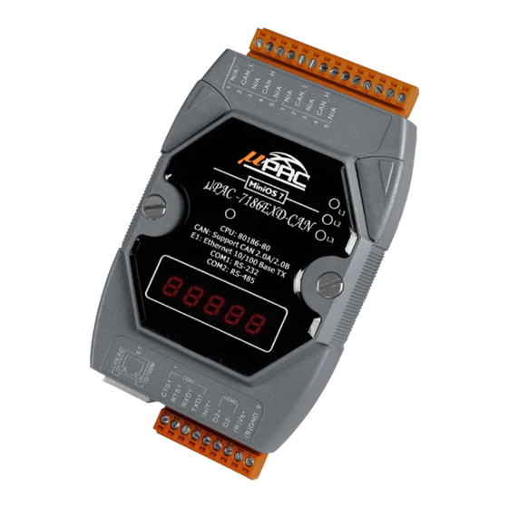
2.2 μPAC-7186EXD-CAN Hardware Structure CAN Bus Bypass CAN Connector Bus Connector L1, L2, and L3 LEDs Round LED 7-segment Power Pin Ethernet port COM2: RS-485 Port COM1: RS-232 Port I-7188XBD-CAN/μPAC-7186EXD-CAN user manual (ver.1.0.3, May/09/2014) -
Page 11: Can Network Wire Connection
2.3 CAN Network Wire Connection In order to minimize the reflection effects on the CAN bus line, the CAN bus line has to be terminated at both ends by two terminal resistances as following figure. According to the ISO 11898-2 spec, each terminal resistance is 120Ω... - Page 12 The CAN bus bard rate has the high relationship with the bus length. The following table indicates the corresponding bus length on every kind of baud rate. Baud rate (bit/s) Max. Bus length (m) 800 K 500 K 250 K 125 K 50 K 1000...
-
Page 13: Terminal Resistor Jumper Selection
2.4 Terminal Resistor Jumper Selection Remove the cover of the I-7188XBD-CAN/μPAC-7186EXD-CAN. Users can see the part of internal structure shown as following figure. The XC100 provides users one jumper-selected termination resistor (J3). Its position is displayed below. Figure2.1 XC100 I/O expansion board LAYOUT The jumper J3 is used to judge the resister of CAN network. - Page 14 Apply the termination Don’t apply the termination resistor resistor(120Ω) v1.80 or before v1.90 v1.80 or before v1.90 Table 2.1 J3 Jumper Selections For(μPAC-7186EXD-CAN) For(I-7188XBD-CAN) v1.80 or before v1.90 v1.80 or before v1.90 Table 2.2 J4 Jumper Selections I-7188XBD-CAN/μPAC-7186EXD-CAN user manual (ver.1.0.3, May/09/2014)
-
Page 15: Wiring Diagram For Different Application
2.5 Wiring Diagram For Different Application 2.5.1 Program download If users want to download users’ program, the following structure may be needed. Users must use the download cable (packaged with I-7188XBD-CAN/ μPAC-7186EXD-CAN) to connect the I-7188XBD-CAN/ μPAC-7186EXD-CAN COM1 with PC available COM port. Then, use the tool, 7188xw.exe, in OSImage folder to download users’... - Page 16 Moreover, in order to wire conveniently, the I-7188XBD-CAN/ μPAC-7186EXD-CAN provides not only one CAN port, but also another bypass CAN port. There two CAN ports are the same one. The bypass CAN port is just for wiring with another CAN device conveniently, it doesn’t have any other function.
-
Page 17: I-7188Xbd-Can Di & Do Channel Wiring Diagram
2.5.3 I-7188XBD-CAN DI & DO channel wiring diagram The general wire connection methods for DI channel of I-7188XBD-CAN are shown below. I-7188XBD-CAN I-7188XBD-CAN COM1 COM1 COM2 COM2 Switch Logic Low Logic Hihg Dry Contact Signal Input TTL/CMOS Signal Input I-7188XBD-CAN COM1 COM2 Open-Collector Signal Input... -
Page 18: Xc100 Library
3 XC100 Library The XC100 library file, XC100L.lib, is useful to help user design various CAN devices. Here, the library for TC, BC and MSC is provided to receive CAN messages, transmit CAN messages, and configure the CAN controller. This section will show you what they have and how to use them. - Page 19 P r o j e c t f i l e C / C + + l a n g u a g e s o u r c e c o d e X C 1 0 0 L . l i b C o m p i l e &...
-
Page 20: Library Function Definition And Description
3.1 Library Function Definition and Description The functions of XC100 library file are presented in the following table. They are provided to help users construct their characteristic CAN device. For the detail information of each function, please refer to the following sub-section. Function definition Description Page... -
Page 21: Can_Reset
3.1.1 CAN_Reset Description: Reset the CAN controller by hardware circuit. After running this function, the CAN controller will be set to initial state. For more information about this, please refer to the SJA1000 data sheet on the web site. http://www.semiconductors.philips.com/pip/SJA1000.html#datasheet ... -
Page 22: Xc100Init / Xc100Init_Listen
3.1.2 XC100Init / XC100Init_Listen Description: XC100Init(): Initialize the software buffer and XC100 hardware, which includes CAN controller, L1 LED, L2 LED, L3 LED and then let CAN Bus into operation mode. XC100Init_Listen(): Initialize the software buffer and XC100 hardware, which includes CAN controller, L1 LED, L2 LED, L3 LED and then let CAN Bus into listen only mode. - Page 23 Interrupt Type Meaning Receive Interrupt When a message has been received without errors, the receive interrupt will be triggered. Transmit Interrupt When a message has been successfully transmitted or the transmit buffer is accessible again, the transmit interrupt will be triggered. Error Warning Interrupt If the error or bus status is set or clear, the error interrupt will be triggered.
- Page 24 For 11-bit ID Message: Register bits of register Filter Target AccCode[0] and AccMask[0] bit7~bit0 bit10 ~ bit3 of ID AccCode[1] and AccMask[1] bit7~bit5 bit2 ~ bit0 of ID AccCode[1] and AccMask[1] bit4 AccCode[1] and AccMask[1] bit3~bit0 no use AccCode[2] and AccMask[2] bit7~bit0 bit7 ~ bit0 of 1st byte data AccCode[3] and AccMask[3]...
-
Page 25: Setcanbaud
3.1.3 SetCANBaud Description: This function is used to change the CAN baud after calling XC100init function. Syntax: int SetCANBaud(unsigned long CANBaud, char BT0, char BT1) Parameter: CANBaud, BT0, BT1: Please refer to the parameters description in the XC100Init function in section 3.1.2. -
Page 26: Setcanmask
3.1.4 SetCANMask Description: This function is used to change the CAN message filter after using XC100Init function. Syntax: int SetCANMask(unsigned long AccCode, unsigned long AccMask) Parameter: AccCode, AccMask: Please refer to the parameters description in the XC100Init function in section 3.1.2. ... -
Page 27: Can_Installirq
3.1.5 CAN_InstallIrq Description: Set the interrupt function enable. Afterwards, the CPU of I-7188 series embedded controller can receive the interrupt signal from CAN controller. Syntax: void CAN_InstallIrq(void) Parameter: None Return: None Relative function: 3.1.6 CAN_RemoveIrq I-7188XBD-CAN/μPAC-7186EXD-CAN user manual (ver.1.0.3, May/09/2014) -
Page 28: Can_Removeirq
3.1.6 CAN_RemoveIrq Description: Disable the interrupt function. Afterwards, the CPU of I-7188 series embedded controller can't receive the interrupt signal from CAN controller. Syntax: void CAN_RemoveIrq(void) Parameter: None Return: None Relative function: 3.1.5 CAN_InstallIrq I-7188XBD-CAN/μPAC-7186EXD-CAN user manual (ver.1.0.3, May/09/2014) -
Page 29: Can_Resotre
3.1.7 CAN_Resotre Description: Set the interrupt function disable, release all software buffer, and reset CAN chip. This function must be called to release resource before the program is terminated. Syntax: void CAN_Restore(void) Parameter: None Return: None ... -
Page 30: Can_Createbuffer
3.1.8 CAN_CreateBuffer Description: Call this function for changing the reception and transmission software buffer sizes. If users don't use this function, the default reception and transmission software buffer sizes are both 256 records. Syntax: int CAN_CreateBuffer(int BufMode, unsigned int BufferSize) ... -
Page 31: Sendcanmsg / Sendcanmsg_Nonblock
3.1.9 SendCANMsg / SendCANMsg_NonBlock Description: SendCANMsg(): Send CAN message with blocking method. If the transmission buffer is disable, this function will send a message to the CAN network. However, if the transmit buffer is enable, this function will send all the messages stored in the transmit buffer to the CAN network. - Page 32 DataLen: The pure data length of a CAN messages. The range of this value is 0~8. *Data: Store the data of CAN message. The numbers of data bytes need to match with the "DataLen". Return: CAN_NoError: OK CAN_DataLengthError: Data length of CAN message is over 8.
-
Page 33: Getnonblocktxbufferlockedcount
3.1.10 GetNonBlockTxBufferLockedCount Description: Get transmission buffer locked count of sending CAN messages with non-blocking method. After using SendCANMsg_NonBlock, this API is used for user to get transmission buffer locked error and retry counts. This function is supported by XC100 library v1.80 or later. ... -
Page 34: Getnonblocktxincompletecount
3.1.11 GetNonBlockTxIncompleteCount Description: Get transmission incomplete counts of sending CAN messages with non-blocking method. After using SendCANMsg_NonBlock, this API is used for user to get the transmission incomplete error and retry counts. This function is supported by XC100 library v1.80 or later. ... -
Page 35: Getcanmsg
3.1.12 GetCANMsg Description: Receive CAN messages from receive buffer or from CAN bus directly. If the receive interrupt is set to enable in IntMode parameter of XC100Init function. This function will read back the CAN message stored in the software receive buffer. - Page 36 Return: CAN_NoError: OK CAN_ReceiveBufferEmpty: No message is in the CAN receive buffer. CAN_SoftBufferIsEmpty: No message is in the software receive buffer. CAN_DataLengthError: The Data length of received message is over than 8. Relative function: 3.1.2 XC100Init / XC100Init_Listen I-7188XBD-CAN/μPAC-7186EXD-CAN user manual (ver.1.0.3, May/09/2014)
-
Page 37: Getstatus
3.1.13 GetStatus Description: Read the CAN controller status and software buffer overflow flag message. Syntax: void GetStatus(unsigned char *CANReg, unsigned char *OverflowFlag) Parameter: *CANReg: The pointer for obtain the current CAN controller status. For the information about the CANReg value meaning, please refer to the following table. -
Page 38: Clearstatus
3.1.14 ClearStatus Description: This function is used for cleaning the CAN reception or transmission software buffer overflow flag. When one of these two buffers is full, the corresponding overflow flag will be set to 1. In this case, users need to use this function to clear the overflow flag to acknowledge the error information. -
Page 39: L1Off
3.1.15 L1Off Description: Turn the L1 LED off. About the position of L1 LED, please refer to the figure 2.1 in the section 2.1. Syntax: void L1Off(void) Parameter: None Return: None Relative function: 3.1.18 L1On I-7188XBD-CAN/μPAC-7186EXD-CAN user manual (ver.1.0.3, May/09/2014) -
Page 40: L2Off
3.1.16 L2Off Description: Turn the L2 LED off. About the position of L2 LED, please refer to the figure 2.1 in the section 2.1. Syntax: void L2Off(void) Parameter: None Return: None Relative function: 3.1.19 L2On I-7188XBD-CAN/μPAC-7186EXD-CAN user manual (ver.1.0.3, May/09/2014) -
Page 41: L3Off
3.1.17 L3Off Description: Turn the L3 LED off. About the position of L3 LED, please refer to the figure 2.1 in the section 2.1. Syntax: void L3Off(void) Parameter: None Return: None Relative function: 3.1.20 L3On I-7188XBD-CAN/μPAC-7186EXD-CAN user manual (ver.1.0.3, May/09/2014) -
Page 42: L1On
3.1.18 L1On Description: Turn the L1 LED on. About the position of L1 LED, please refer to the figure 2.1 in the section 2.1. Syntax: void L1On(void) Parameter: None Return: None Relative function: 3.1.15 L1Off I-7188XBD-CAN/μPAC-7186EXD-CAN user manual (ver.1.0.3, May/09/2014) -
Page 43: L2On
3.1.19 L2On Description: Turn the L2 LED on. About the position of L2 LED, please refer to the figure 2.1 in the section 2.1. Syntax: void L2On(void) Parameter: None Return: None Relative function: 3.1.16 L2Off I-7188XBD-CAN/μPAC-7186EXD-CAN user manual (ver.1.0.3, May/09/2014) -
Page 44: L3On
3.1.20 L3On Description: Turn the L3 LED on. About the position of L3 LED, please refer to the figure 2.1 in the section 2.1. Syntax: void L3On(void) Parameter: None Return: None Relative function: 3.1.17 L3Off I-7188XBD-CAN/μPAC-7186EXD-CAN user manual (ver.1.0.3, May/09/2014) -
Page 45: Usercanint
3.1.21 UserCANInt Description: This function is created by users and is used to program the CAN interrupt service routine by users. The parameter CANINT is passed automatically when the interrupt functions are triggered. It indicates what kinds of CAN controller interrupt are active. Therefore, users only need to design their interrupt routine according to dealing with different interrupt functions. - Page 46 0x10 CAN controller wake-up 0x20 Bus Passive 0x40 Arbitration Lost 0x80 Bus Error Return: None Relative function: 3.1.2 XC100Init / XC100Init_Listen I-7188XBD-CAN/μPAC-7186EXD-CAN user manual (ver.1.0.3, May/09/2014)
-
Page 47: Can_Searchbaud
3.1.22 CAN_SearchBaud Description: Enter “Listen Only Mode” and enable receive and error interrupt to detect the right bit-rate of the CAN bus. Upon successful reception of a message, the “CAN_NoError” message will be return. Otherwise, the “CAN_AutoBaudTimeout” message will be return ... -
Page 48: Can_Busoff_Recovery
3.1.23 CAN_BusOff_Recovery Description: When the CAN Bus status becomes “Bus Off”, user can use this func- tion to recover the status to active status. This function is supported by XC100 library v1.80 or later. Syntax: void CAN_BusOff_Recovery(void) Parameter: None ... -
Page 49: Table Of Return Code
3.2 Table of Return Code Return Error ID Comment Code CAN_NoError CAN_ResetError Enter reset mode error CAN_ConfigError CAN chip configure error CAN_SetACRError Set to Acceptance Code Register error CAN_SetAMRError Set to Acceptance Mask Register error CAN_SetBaudRateError Set Baud Rate error CAN_InstallIrqFailure Enable interrupt functions failure CAN_RemoveIrqFailure... -
Page 50: Demo Programs
4 Demo Programs following architecture shown I-7188XBD-CAN uPAC-7186EXD-CAN folder. Users manual |--\document OS image used for testing demo |--\OSimage demo folier |--\demo BC++3.1 library folder |--\LIB100 BC++3.1 demo folder |--\BCPP31 BC++3.1 AC_AM demo folder |--\AC_AM ... - Page 51 Here, the demo programs of XC100 library file with BC++3.1, TC++1.01 and MSC 1.52 are provided. The content of each demo is displayed in the following table. When users want to compile the demo program, please move the demo folder into a new folder named with max 8 letters. The BC++3.1/TC++1.01/MSC6 compilers are 16-bit compilers and may have a trouble because of the long file name.
-
Page 52: Program Download Procedure
4.1 Program Download Procedure Here, it is considered that how to build an execution file with XC100L.lib and how to run this program on the I-7188XBD-CAN/μPAC-7186EXD-CAN. Step1: Create a folder named “MyDemo” in the C disk. Step2: Copy the lib folder from the lib100 folder and users program into the MyDemo folder. - Page 53 Step3: Run the TC++1.01 development environment. Click the “Options\Full menus” to expand the all functions of menus. Users can free download the TC++1.01 from the following web site. http://comsmunity.borland.com/museum Step4: Click the “Project\Open project…” to create a new project named “AC_AM.PRJ”.
- Page 54 Step5: Search all library file by setting *.lib in the Name filed. Then, use the “Add” function to add the library file “XC100L.lib” into MyDemo project. Step6: Following the step5 to add another two files. One is “7188XBL.lib”. If users use the μPAC-7186EXD-CAN, the library file is “7186EL.lib”. Another one is users’...
- Page 55 Step7: Click the “Options/Compiler/Code generation…” to set the compile mode to the large mode. Afterwards, click “More…” to set the “Floating point” and “Instruction Set” parameters. The Emulation and 80186 will be used respectively. Then, click OK button to save the configuration. Step8: Click the “Option/Debugger...”...
- Page 56 Step9: Click the “Option/Directories...” to set the “Output Directory” parameter. Here, set the “C:\MyDemo” for the “Output Directory” parameter. Step10: After finishing all the parameters setting, click the “Compile/build all” to produce the execution file named “AC_AM.exe”. I-7188XBD-CAN/μPAC-7186EXD-CAN user manual (ver.1.02, July/14/2008) ------56...
- Page 57 Step11: Copy the file 7188xw.exe into the MyDemo folder. Then, double-click the 7188xw.exe file. The 7188xw.exe can be found in the OSimage folder. Step12: If the COM1 I-7188XBD-CAN is connected to the PC COM1, the hint sign,”I-7188XB>”, will be shown in the 7188xw.exe window after pressing the Enter key in the 7188xw.exe program.
- Page 58 Step14: After finishing the download procedure, key in the command, “run”, to implement the execution file,”AC_AM.exe”. I-7188XBD-CAN/μPAC-7186EXD-CAN user manual (ver.1.02, July/14/2008) ------58...
Need help?
Do you have a question about the mPAC-7186EXD-CAN and is the answer not in the manual?
Questions and answers