Table of Contents
Advertisement
Quick Links
CAN-8124/ CAN-8224/ CAN-8424
DeviceNet Slave Device
Warranty
All products manufactured by ICP DAS are warranted
against defective materials for a period of one year from
the date of delivery to the original purchaser.
Warning
ICP DAS assumes no liability for damages consequent
to the use of this product. ICP DAS reserves the right to
change this manual at any time without notice. The
information furnished by ICP DAS is believed to be
accurate and reliable. However, no responsibility is
assumed by ICP DAS for its use, or for any infringements
of patents or other rights of third parties resulting from its
use.
Copyright
Copyright 2007 by ICP DAS Co., LTD. All rights
reserved worldwide.
Trademark
The names used for identification only may be
registered trademarks of their respective companies.
CAN-8124/ CAN-8224/ CAN-8424 User Manual (Version 2.0, Aug/2007)
CAN-8124/CAN-8224/CAN-8424 User Manual
User Manual
1/153
Advertisement
Table of Contents

Related Manuals for ICP DAS USA CAN-8124


Summary of Contents for ICP DAS USA CAN-8124
- Page 1 Copyright Copyright 2007 by ICP DAS Co., LTD. All rights reserved worldwide. Trademark The names used for identification only may be registered trademarks of their respective companies. CAN-8124/ CAN-8224/ CAN-8424 User Manual (Version 2.0, Aug/2007) 1/153...
-
Page 2: Table Of Contents
4.6.2 Poll I/O connection....................... 43 4.6.3 Bit–Strobe I/O Connection ..................44 4.6.4 Change of State or Cyclic I/O Connection (Acknowledge) ........45 4.6.5 Change of State or Cyclic I/O Connection (Unacknowledge) ........46 CAN-8124/ CAN-8224/ CAN-8424 User Manual (Version 2.0, Aug/2007) 2/153... - Page 3 9.6 Problem: Why can I not to communicate any IO message with the device? ............................138 9.7 Problem: How to get IO data from CAN-8x24? ............ 139 Appendix A: Dimension.................. 142 Appendix B: Analog I/O Transformation Table..........144 CAN-8124/ CAN-8224/ CAN-8424 User Manual (Version 2.0, Aug/2007) 3/153...
-
Page 4: Chapter 1 Introduction
Each expansion slot can have one I-87K or I-8000 series I/O module plugged into it. For example, an CAN-8124 has one expansion slot, and an CAN-8424 has 4 expansion slots. All of these main control units follow the DeviceNet specification Volume I, Release 2.0&... - Page 5 CAN-8124/CAN-8224/CAN-8424 User Manual Figure 1-1 DeviceNet application CAN-8124/ CAN-8224/ CAN-8424 User Manual (Version 2.0, Aug/2007) 5/153...
-
Page 6: Hardware Features
Power Supply:20W, Unregulated +10VDC to +30VDC Operating Temperature:-25°C to +75°C Storage Temperature:-30°C to +85°C Humidity:5%~95% COM1 (CAN-8424 only) RS-232: TXD,RXD,RTS,CTS,GND Communication speed: 115200 bps. Configure tool connection CAN-8124/ CAN-8224/ CAN-8424 User Manual (Version 2.0, Aug/2007) 6/153... -
Page 7: Can-8124/Can-8224/Can-8424 Devicenet Features
NET, MOD and Power Led directors 1.4 Utility Feature Support I-8k/I-87K modules Show I-8k/I-87K modules configuration Show Application and assembly objects configuration Support IO connection path setting Support EDS file creating CAN-8124/ CAN-8224/ CAN-8424 User Manual (Version 2.0, Aug/2007) 7/153... -
Page 8: Chatper 2 Hardware Specification
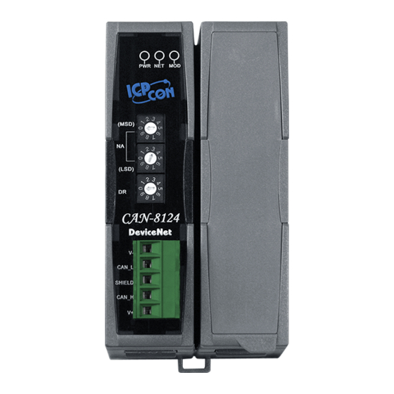
Chatper 2 Hardware Specification 2.1 CAN-8124/CAN-8224 Hardware Structure DeviceNet Power LED Status LED Node ID and Baud rate rotary switch CAN Bus Connector 1 I/O Expansion Slot 2 I/O Expansion Slots CAN-8124/ CAN-8224/ CAN-8424 User Manual (Version 2.0, Aug/2007) 8/153... -
Page 9: Can-8424 Hardware Structure
CAN-8124/CAN-8224/CAN-8424 User Manual 2.2 CAN-8424 Hardware Structure DeviceNet Power LED Status LED RS-232 Port (connect to PC) Power Pin CAN Bus Connector 4 I/O Expansion Slots CAN-8124/ CAN-8224/ CAN-8424 User Manual (Version 2.0, Aug/2007) 9/153... -
Page 10: Wire Connection
(meter) Resistance (Ω) (Type) (mΩ/m) 0.25(23AWG)~ 0~40 124 (0.1%) 0.34mm (22AWG) 0.34(22AWG)~ 40~300 < 60 127 (0.1%) 0.6mm (20AWG) 0.5~0.6mm 300~600 < 40 150~300 (20AWG) 0.75~0.8.mm 600~1K < 20 150~300 (18AWG) CAN-8124/ CAN-8224/ CAN-8424 User Manual (Version 2.0, Aug/2007) 10/153... - Page 11 CAN-8124/CAN-8224/CAN-8424 User Manual In the CAN-8124/CAN-8224/CAN-8424, the 120Ω terminal resistance is supplied. The JP2 for the CAN-8124/CAN-8224 is for terminal resistance. The JP2 position is shown in the following figure. JP1 on CAN-8424 is used for adjusting terminal resistance, and its position is shown in the following figure.
- Page 12 Note: When the bus length is greater than 1000m, bridge or repeater devices may be needed. The pin assignments for these CAN-8124/ CAN-8224 and CAN-8424 CAN bus connectors are shown in figure 2-2, figure 2-3, table 2-3 and table 2-4.
- Page 13 Pin 1 Pin 2 CAN_L Pin 3 SHIELD CAN_H Pin 4 Pin 5 Figure 2-3 The connector pin assignments for the CAN-8124/CAN-8224 Table 2-4 Connector pins of CAN-8124/CAN-8224 Pin No. Signal Description Ground (0V) CAN_L CAN_L bus line (dominant low)
-
Page 14: Pwr Led
The corresponding conditions are given in table 2-5. Table 2-5 PWR led conditions condition status indicates No power No power supply Solid red Normal Device is working CAN-8124/ CAN-8224/ CAN-8424 User Manual (Version 2.0, Aug/2007) 14/153... -
Page 15: Devicenet Led
Table 2-6 The MOD led conditions condition status indicates Normal Solid Critical fault Device has unrecoverable fault; Flashing Non_critical fault Device has recoverable fault; to recover: Reconfigure device Reset device Perform error recovery CAN-8124/ CAN-8224/ CAN-8424 User Manual (Version 2.0, Aug/2007) 15/153... -
Page 16: Net Led
Solid On line, communicating DeviceNet is online and communicating CAN-8124/ CAN-8224/ CAN-8424 User Manual (Version 2.0, Aug/2007) 16/153... -
Page 17: Na And Dr Rotary Switch
CAN-8124/CAN-8224/CAN-8424 is 32, if the MSD rotary switch is turned to 3 and the LSD rotary switch is turned to 2 as in figure 2-5. Figure 2-5 NA rotary switches CAN-8124/ CAN-8224/ CAN-8424 User Manual (Version 2.0, Aug/2007) - Page 18 The DeviceNet firmware built in the CAN-8x24 will not be executed. Before users employ the utility tool to configure the CAN-8x24, the initial mode is needed. Because the CAN-8124/CAN-8224 has no RS-232 COM Port, it is necessary to run this utility tool in the off-line mode if users want to get the EDS file of users’...
-
Page 19: Module Support
CAN-8124/CAN-8224/CAN-8424 User Manual 2.7 Module Support CAN-8124/CAN-8224/CAN-8424 supports many kinds of DI, DO, AI and AO modules for the I-8000/I-87K series modules. When users want to use these modules on the DeviceNet network, they only need to plug these modules into the CAN-8124/CAN-8224/CAN-8424 I/O expansion slots. Then,... -
Page 20: Application Flowchart
CAN-8124/CAN-8224/CAN-8424 User Manual 2.8 Application Flowchart The procedure to follow on how to use the CAN-8124/CAN-8224/ CAN-8424 is as follows. Users can refer to the procedure to apply the CAN-8124/CAN-8224/CAN-8424 devices to the DeviceNet application as in figure 2-7. Figure 2-7 CAN-8124/CAN-8224/CAN-8424 application flowchart CAN-8124/ CAN-8224/ CAN-8424 User Manual (Version 2.0, Aug/2007) -
Page 21: Chapter 3 Devicenet System
The endpoints of a connection are applications that need to share data. Figure 3.1 shows the DeviceNet layer in the control and information layers. CAN-8124/ CAN-8224/ CAN-8424 User Manual (Version 2.0, Aug/2007) 21/153... - Page 22 Connection Set for users to establish connections. The Predefined Master/Slave Connection Set is a set of Connections that facilitate communications typically seen in a Master/Slave relationship. Many of the steps involved in the creation and configuration of an application-to-application CAN-8124/ CAN-8224/ CAN-8424 User Manual (Version 2.0, Aug/2007) 22/153...
- Page 23 Slave’s Explicit/ Unconnected Response Messages/ Device Heartbeat Message/ Device Shutdown Message 1 0 0 Destination MAC ID Master’s Explicit Request Messages 1 0 1 Destination MAC ID Master’s I/O Poll Command/Change of State/Cyclic Message CAN-8124/ CAN-8224/ CAN-8424 User Manual (Version 2.0, Aug/2007) 23/153...
- Page 24 The object model provides a template for organizing and implementing the Attributes (data), Services (methods or procedures) and behaviors of the components within a DeviceNet product. Figure 3.2 depicts the object model for CAN-8124/CAN-8224 (Group 2 server Only). The next section would explain these objects.
-
Page 25: Predefined Master Slave Connection Set
Messaging Connection and allows for several different I/O connections which include a Bit Strobe Command/Response, Poll Command/Response, Change of State and Cyclic connections. The following types of messages are processed by a DeviceNet Slave CAN-8124/ CAN-8224/ CAN-8424 User Manual (Version 2.0, Aug/2007) 25/153... -
Page 26: Explicit Messages
Explicit Request massage. Within a Slave Explicit Request and Response Messages are received/transmitted by a single Connection Object. The architecture is as figure 3.3. Figure 3.3 the architecture of Explicit message CAN-8124/ CAN-8224/ CAN-8424 User Manual (Version 2.0, Aug/2007) 26/153... -
Page 27: I/O Bit Strobe Messages
Bit-Strobe Command has been received. Within a Slave the two messages are received/ transmitted by a single Connection Object. The architecture is as in figure 3.4. Figure 3.4 the architecture of IO bit strobe message CAN-8124/ CAN-8224/ CAN-8424 User Manual (Version 2.0, Aug/2007) 27/153... -
Page 28: I/O Poll Messages
Slave transmits back to the Master when the Poll Command is received. Within a Slave the two messages are received/transmitted by a single Connection Object as in figure 3-5. Figure 3-5 the architecture of poll IO message CAN-8124/ CAN-8224/ CAN-8424 User Manual (Version 2.0, Aug/2007) 28/153... -
Page 29: I/O Change Of State/Cyclic Messages
Object. The architecture for these messages can be seen in figure 3-6 and figure 3-7. Figure 3-6 the architecture of the IO COS message Figure 3-7 the architecture of the IO Cyclic message CAN-8124/ CAN-8224/ CAN-8424 User Manual (Version 2.0, Aug/2007) 29/153... -
Page 30: Eds File
ICP DAS provides CAN utilities, so that users can setup their own EDS file. You can use the EDS file in the DeviceNet Master to access DeviceNet Slave devices. The CAN utility is a very powerful tool for the CAN-8124/ CAN-8224/ CAN-8424 User Manual (Version 2.0, Aug/2007) 30/153... - Page 31 CAN-8224. However, users can only use off-line mode to create EDS files of CAN-8124/ CAN-8224 with the specific IO modules. It also provides a graph interface for users to be able to make up their own EDS file system. For more detailed information on this topic, please refer to the next section.
-
Page 32: Chapter 4 Devicenet Profile Area
Chapter 4 DeviceNet Profile Area This chapter is for users who want to get and understand more detailed information relating to the CAN-8124/CAN-8224/CAN-8424 device when using the DeviceNet protocol. This section documents the detailed functions for each object class that is implemented in the DeviceNet network. -
Page 33: Identity Object (Class Id: 0X01)
UINT Product UINT 2(CAN-8124/CAN-8224)/3(CAN-8424) code Revision Struct of 1.03 vision USINT Major USINT Revision Minor Revision Status WORD Serial UDINT 2(CAN-8124/CAN-8224)/3(CAN-8424) number Product Short_String Note name Heartbeat Get/Set USINT 0(default) Interval CAN-8124/ CAN-8224/ CAN-8424 User Manual (Version 2.0, Aug/2007) 33/153... - Page 34 CAN-8124/CAN-8224/CAN-8424 User Manual Instance Service Service Code Service name Support 0x0E Get_Attribute_Single 0x10 Set_Attribute_Single 0x05 Reset CAN-8124/ CAN-8224/ CAN-8424 User Manual (Version 2.0, Aug/2007) 34/153...
-
Page 35: Devicenet Object (Class Id:0X03)
Reset or Power-up Baud Rate BOOL 0=No Change Switch Changed 1=Change since last Reset or Power-up MAC ID Switch USINT Range 0-99 Value Baud Rate USINT Range 0-9 Switch Value CAN-8124/ CAN-8224/ CAN-8424 User Manual (Version 2.0, Aug/2007) 35/153... - Page 36 CAN-8124/CAN-8224/CAN-8424 User Manual Instance Service Service Code Service name Support 0x0E Get_Attribute_Single 0x10 Set_Attribute_Single CAN-8124/ CAN-8224/ CAN-8424 User Manual (Version 2.0, Aug/2007) 36/153...
-
Page 37: Assembly Object (Class Id: 0X04)
0x03 Data Get/Set plugged in the users device Note: In CAN-8x24 device, the statart-up number of assembly instance is 0x64. Instance service Service Code Service name Support 0x0E Get_Attribute_Single 0x10 Set_Attribute_Single CAN-8124/ CAN-8224/ CAN-8424 User Manual (Version 2.0, Aug/2007) 37/153... -
Page 38: Application Object (Class Id:0X64)
0x07 DO Length CHAR 0x08 AO Length CHAR 0x09 DI Length CHAR 0x0A AI Length CHAR 0x0B DO channel num CHAR 0x0C AO channel num CHAR 0x0D DI channel num CHAR CAN-8124/ CAN-8224/ CAN-8424 User Manual (Version 2.0, Aug/2007) 38/153... - Page 39 This attribute includes the total length of this module. In analog modules, the unit of length is 2 bytes. And 1 bit is corresponding to a channel in the digital modules. CAN-8124/ CAN-8224/ CAN-8424 User Manual (Version 2.0, Aug/2007) 39/153...
- Page 40 The attribute indicates the DI data of the module. AI data The attribute indicates the AI data of the module. Instance service Service Code Service name Support 0x0E Get_Attribute_Single 0x10 Set_Attribute_Single CAN-8124/ CAN-8224/ CAN-8424 User Manual (Version 2.0, Aug/2007) 40/153...
-
Page 41: Connection Object (Class Id:0X05)
Note: In CAN-8x24, the default IO connection path is its Assembly Object. Please use the CAN Slave Utility to set the IO connection path. For CAN-8124/ CAN-8224, it is needed to set the path via the CAN bus via explicit message. -
Page 42: Explicit Connection
USINT 0x0D produced_connection_path_ length UINT 0x0E produced_connection_path EPATH Empty 0x0F consumed_connection_path_length UINT 0x10 consumed_connection_path EPATH Empty 0x11 production_inhibit_time UINT Instance service Service Code Service name Support 0x0E Get_Attribute_Single 0x10 Set_Attribute_Single CAN-8124/ CAN-8224/ CAN-8424 User Manual (Version 2.0, Aug/2007) 42/153... -
Page 43: Poll I/O Connection
0x0E produced_connection_path EPATH specified default 0x0F consumed_connection_path_length UINT specified default 0x10 consumed_connection_path EPATH specified default 0x11 production_inhibit_time UINT Instance service Service Code Service name Support 0x0E Get_Attribute_Single 0x10 Set_Attribute_Single CAN-8124/ CAN-8224/ CAN-8424 User Manual (Version 2.0, Aug/2007) 43/153... -
Page 44: Bit-Strobe I/O Connection
0x0E produced_connection_path EPATH specified default 0x0F consumed_connection_path_length UINT specified default 0x10 consumed_connection_path EPATH specified default 0x11 production_inhibit_time UINT Instance service Service Code Service name Support 0x0E Get_Attribute_Single 0x10 Set_Attribute_Single CAN-8124/ CAN-8224/ CAN-8424 User Manual (Version 2.0, Aug/2007) 44/153... -
Page 45: Change Of State Or Cyclic I/O Connection (Acknowledge)
0x0E produced_connection_path EPATH specified default 0x0F consumed_connection_path_length UINT specified default 20h 2Bh 24h 0x10 consumed_connection_path EPATH 0x11 production_inhibit_time UINT Instance service Service Code Service name Support 0x0E Get_Attribute_Single 0x10 Set_Attribute_Single CAN-8124/ CAN-8224/ CAN-8424 User Manual (Version 2.0, Aug/2007) 45/153... -
Page 46: Change Of State Or Cyclic I/O Connection (Unacknowledge)
UINT specified default 0x0E produced_connection_path EPATH specified default 0x0F consumed_connection_path_length UINT 0x10 consumed_connection_path EPATH Empty 0x11 production_inhibit_time UINT Instance service Service Code Service name Support 0x0E Get_Attribute_Single 0x10 Set_Attribute_Single CAN-8124/ CAN-8224/ CAN-8424 User Manual (Version 2.0, Aug/2007) 46/153... - Page 47 CAN-8124/CAN-8224/CAN-8424 User Manual Note : The first assembly instance number in the CAN-8124/CAN-8224/ CAN-8424 is 0x64. The second is 0x65. The priority of Assembly instances follow the DO, AO, DI and AI order. There are many examples for users to go through in order to better understand Assembly objects.
-
Page 48: Chapter 5 Configuration & Getting Started
3. Produce the corresponding EDS file. 1. Reset the CAN-8124/CAN-8224 device with the proper node ID and baud rate. 2. Apply the EDS file in your DeviceNet. 3. Start to communicate with the DeviceNet Master Interface CAN-8124/ CAN-8224/ CAN-8424 User Manual (Version 2.0, Aug/2007) 48/153... -
Page 49: Can-8424 Configuration Flowchart
2. Execute CAN Slave Utility to configure the CAN-8424 device and create the EDS file. After configuring CAN-8424 and creating the specific EDS files, apply the EDS file in your DeviceNet CAN-8124/ CAN-8224/ CAN-8424 User Manual (Version 2.0, Aug/2007) 49/153... -
Page 50: Can Slave Utility Overview
CAN-8124/CAN-8224/CAN-8424 User Manual 5.3 CAN Slave Utility Overview The CAN Slave Utility is designed for the CAN-8124/ CAN-8224/ CAN-8424. It provides the following functions. Configures the input range of the I-8000 and I-87K AI/AO modules plugged in the CAN-8124/CAN-8224/CAN-8424. Scans the I-8000 or I-87K modules in the I-8x20. Then, it creates EDS files to match the scan results in the on-line mode. -
Page 51: Configuration With The Can Slave Utility
“/CAN-CD/DeviceNet/Slave/CAN-8x24/Utility/. Step 2: Execute the setup.exe file to install the CAN Slave Utility. Step 3: A “Welcome” window will pop up to prompt the user to begin installation. CAN-8124/ CAN-8224/ CAN-8424 User Manual (Version 2.0, Aug/2007) 51/153... - Page 52 Step 5: Click the “Next” button. A “Ready to Install the Program” window will pop up. Here, press the “Install” button to install the Utility. CAN-8124/ CAN-8224/ CAN-8424 User Manual (Version 2.0, Aug/2007) 52/153...
- Page 53 “Finish” the successful completion of the installation. Step 7: After finishing the installation of the CAN Slave Utility, users can find the CAN_SL Utility as shown in the following screenshot. CAN-8124/ CAN-8224/ CAN-8424 User Manual (Version 2.0, Aug/2007) 53/153...
- Page 54 Step 1: Click “Start” in the task bar, then click Settings/Control Panel. Step 2: Click the “Add/Remove Programs” button icon to open the dialog. Step 3: Find out the CAN_SL Utility, and click the Change/Remove button. CAN-8124/ CAN-8224/ CAN-8424 User Manual (Version 2.0, Aug/2007) 54/153...
- Page 55 CAN-8124/CAN-8224/CAN-8424 User Manual Step 4: Select the “Remove” option and press the “Next” button to remove the software. Step 5: Click the “Yes” button to remove the software. CAN-8124/ CAN-8224/ CAN-8424 User Manual (Version 2.0, Aug/2007) 55/153...
- Page 56 CAN-8124/CAN-8224/CAN-8424 User Manual Step 6: Finally, click the “Finish” button to finish the uninstall process. CAN-8124/ CAN-8224/ CAN-8424 User Manual (Version 2.0, Aug/2007) 56/153...
-
Page 57: Can-8124/ Can-8224 Configuration (Off-Line Mode)
Kbps, then users must set the file’s correct value for the CAN-8224 node id and baud rate in the “NODE ID” and “CAN Baud rate”. Then, select the “2 Slot” as the number of slots under “Slot Number”. CAN-8124/ CAN-8224/ CAN-8424 User Manual (Version 2.0, Aug/2007) 57/153... - Page 58 Step 4: If the I-8024 and I-8042 modules are plugged into slot 0 and slot 1 respectively, then, select 8024 from the list box, and click the “Apply Module” button to save this configuration. CAN-8124/ CAN-8224/ CAN-8424 User Manual (Version 2.0, Aug/2007) 58/153...
- Page 59 Step 6: Repeat steps 4~6 to configure slot 1 with the I-8042 module. Then, click the “Save Setting” button to finish the off-line parameter settings. CAN-8124/ CAN-8224/ CAN-8424 User Manual (Version 2.0, Aug/2007) 59/153...
- Page 60 Alternatively users can move the mouse pointer over the slot module to show the modules name and information displayed in the “Module Information” frame. Then, click the “Build EDS file” button to go to the next step. CAN-8124/ CAN-8224/ CAN-8424 User Manual (Version 2.0, Aug/2007) 60/153...
- Page 61 CAN-8124/CAN-8224/CAN-8424 User Manual Step 8: In this step users can begin building the specific EDS files for their CAN-8124/ CAN-8224. In this dialog, users can know the information of IO modules, assembly components and application instances. Due to the off-line mode, the output and input instance parameters are not able to be set.
- Page 62 CAN-8124/CAN-8224/CAN-8424 User Manual By clicking the “Module View” button, the following figure will be displayed. Clicking on the “Assembly Object View” button, the following figure will be displayed. CAN-8124/ CAN-8224/ CAN-8424 User Manual (Version 2.0, Aug/2007) 62/153...
- Page 63 “Back” button to go back to the above step. Step 10: The next step shows the settable connection path. The connection path in the CAN-8124/CAN-8224 device is default path. Users can refer to the settable path to set these IO connection paths. The application and assembly object instance can also be shown in this figure.
- Page 64 EDS file for users as in the following figure. Step 13: When this process is finished, the main window will pop-up. Then select “Exit program” to exit the program. CAN-8124/ CAN-8224/ CAN-8424 User Manual (Version 2.0, Aug/2007) 64/153...
- Page 65 CAN-8124/CAN-8224/CAN-8424 User Manual You can find the EDS file for the specific CAN-8124/CAN-8224. The file name is ICPDNS1.eds. “1” represents the Node ID of the device. Therefore, users can apply the EDS file in the DeviceNet application as the following figure.
-
Page 66: Can-8424 Configuration (On-Line Mode)
I-8057, I-8053, I-8024 and I-8017H are plugged into slots 0, 1, 2 and 3 respectively. Step 1: Turn off the CAN-8424. Set the “DR” rotary switch for the CAN-8424 to 9. Then turn on the CAN-8424. CAN-8124/ CAN-8224/ CAN-8424 User Manual (Version 2.0, Aug/2007) 66/153... - Page 67 Click the “Connect” button to store the information into the CAN-8424. Then press the “Connect” button to connect to the CAN-8424. The utility will scan the IO modules plugged into the CAN-8424 automatically. CAN-8124/ CAN-8224/ CAN-8424 User Manual (Version 2.0, Aug/2007) 67/153...
- Page 68 Step 5: In the “CAN Slave Device situation” section, press the specific modules and their module configuration information will be revealed in the right upper window. Furthermore users can set their specific module configuration. CAN-8124/ CAN-8224/ CAN-8424 User Manual (Version 2.0, Aug/2007) 68/153...
- Page 69 Step 7: After finishing the process of configuration, press the “Build EDS file” to button to go to the next step to start to build the specific EDS file for your I-8x20. CAN-8124/ CAN-8224/ CAN-8424 User Manual (Version 2.0, Aug/2007) 69/153...
- Page 70 Step 8: The dialog will be displayed as follows. In this dialog, users can defined their needed assembly objects. Step 9: Set the output instance and input instance to either default or user defined mode. CAN-8124/ CAN-8224/ CAN-8424 User Manual (Version 2.0, Aug/2007) 70/153...
- Page 71 Assembly instance information. Users cannot modify the assembly instance components. Step 10: In addition, the utility also provides module, assembly and application object information by pressing the “Module view”, “Assembly Object View” and “Application View” buttons. CAN-8124/ CAN-8224/ CAN-8424 User Manual (Version 2.0, Aug/2007) 71/153...
- Page 72 CAN-8124/CAN-8224/CAN-8424 User Manual Step 11: If you press the “Module View” button, the “Module Information” window will pop-up. Users can get the IO module plugged into the CAN-8424 from this dialog. CAN-8124/ CAN-8224/ CAN-8424 User Manual (Version 2.0, Aug/2007) 72/153...
- Page 73 CAN-8124/CAN-8224/CAN-8424 User Manual Step 12: By pressing the “Assembly Object View” button, the “Assembly Object Information” window will pop-up. Users can get every assembly object information in the CAN-8424 from this dialog. CAN-8124/ CAN-8224/ CAN-8424 User Manual (Version 2.0, Aug/2007) 73/153...
- Page 74 Step 14: After creating the assembly object, press the “NEXT” button to go to the next step. Alternatively you can press the “Back” button to go back to the above step. CAN-8124/ CAN-8224/ CAN-8424 User Manual (Version 2.0, Aug/2007) 74/153...
- Page 75 Users can set their EDS files information from here. Step 16: Users can set the specified information they want in the below fields. This information will be stored in the EDS file. CAN-8124/ CAN-8224/ CAN-8424 User Manual (Version 2.0, Aug/2007) 75/153...
- Page 76 EDS file for the CAN-8424. Otherwise press the “Back” button to go back to the above step. Users can then find the EDS file in the execute file path. CAN-8124/ CAN-8224/ CAN-8424 User Manual (Version 2.0, Aug/2007) 76/153...
-
Page 77: Chapter 6 Components Of Assembly Objects
However, the number of assembly objects is only a default setting in the CAN-8124/CAN-8224. Every IO slot modules represents an application object instance. The CAN-8x24 device would arrange the application instances in order by slot address. - Page 78 CAN-8124/CAN-8224/CAN-8424 User Manual Figure 6-1 DeviceNet object sketch map Note: The max number in the assembly instance is 8. CAN-8124/ CAN-8224/ CAN-8424 User Manual (Version 2.0, Aug/2007) 78/153...
-
Page 79: Can-8424 Assembly Example
Because there are four slots in the CAN-8424, the application instance number is 4. The corresponding Instance attribute is as follows: Application Instance 1 Attribute ID Description Method Data Type Value CAN-8124/ CAN-8224/ CAN-8424 User Manual (Version 2.0, Aug/2007) 79/153... - Page 80 AO data module channel Defined by 0x16 DI data module channel and 2 bytes (1 Defined by channel) 0x17 AI data module channel and 4 bytes (2 channel) and 6 bytes (3 CAN-8124/ CAN-8224/ CAN-8424 User Manual (Version 2.0, Aug/2007) 80/153...
- Page 81 DO Length CHAR 0x08 AO Length CHAR 0x09 DI Length CHAR 0x0A AI Length CHAR DO channel 0x0B CHAR AO channel 0x0C CHAR DI channel 0x0D CHAR AI channel 0x0E CHAR CAN-8124/ CAN-8224/ CAN-8424 User Manual (Version 2.0, Aug/2007) 81/153...
- Page 82 Defined by channel) 0x15 AO data module channel and 6 bytes (3 channel) and 8 bytes (4 channel) Defined by 0x16 DI data module channel Defined by 0x17 AI data module channel CAN-8124/ CAN-8224/ CAN-8424 User Manual (Version 2.0, Aug/2007) 82/153...
- Page 83 Defined by channel) 0x14 DO data module channel bit of 1 byte (4 channel) bit of 1 byte (5 channel) bit of 1 byte (6 channel) bit of 1 byte (7 CAN-8124/ CAN-8224/ CAN-8424 User Manual (Version 2.0, Aug/2007) 83/153...
- Page 84 2 byte (15 channel) bit of 2 byte (16 channel) Defined by 0x15 AO data module channel Defined by 0x16 DI data module channel Defined by 0x17 AI data module channel CAN-8124/ CAN-8224/ CAN-8424 User Manual (Version 2.0, Aug/2007) 84/153...
- Page 85 Defined by bit of 1 byte (3 0x16 DI data module channel channel) bit of 1 byte (4 channel) bit of 1 byte (5 channel) bit of 1 byte (6 CAN-8124/ CAN-8224/ CAN-8424 User Manual (Version 2.0, Aug/2007) 85/153...
- Page 86 2 byte (13 channel) bit of 2 byte (14 channel) bit of 2 byte (15 channel) bit of 2 byte (16 channel) Defined by 0x17 AI data module channel CAN-8124/ CAN-8224/ CAN-8424 User Manual (Version 2.0, Aug/2007) 86/153...
- Page 87 2 bytes and 1 byte is in the digital module. Slot Application Useable Useable Useable Useable Module name Address Instance ID DO unit AO unit DI unit AI unit 0x01 87017 0x02 8024 0x03 8057 0x04 8053 CAN-8124/ CAN-8224/ CAN-8424 User Manual (Version 2.0, Aug/2007) 87/153...
- Page 88 AI (6 CH of I-87017) byte AI (7 CH of I-87017) byte AI (7 CH of I-87017) byte AI (8 CH of I-87017) 0x68 Input byte AI (8 CH of I-87017) CAN-8124/ CAN-8224/ CAN-8424 User Manual (Version 2.0, Aug/2007) 88/153...
- Page 89 WORD 8057 0x02 Module Type CHAR 0 (DO type) Depend on the 0x03 Configuration Get/Set number of 0x40 module channel 0x04 Total Channels CHAR 0x05 Total Length CHAR 0x06 Reserved CHAR CAN-8124/ CAN-8224/ CAN-8424 User Manual (Version 2.0, Aug/2007) 89/153...
- Page 90 2 byte (10 channel) bit of 2 byte (11 channel) bit of 2 byte (12 channel) bit of 2 byte (13 channel) bit of 2 byte (14 channel) CAN-8124/ CAN-8224/ CAN-8424 User Manual (Version 2.0, Aug/2007) 90/153...
- Page 91 DO Length CHAR 0x08 AO Length CHAR 0x09 DI Length CHAR 0x0A AI Length CHAR DO channel 0x0B CHAR AO channel 0x0C CHAR DI channel 0x0D CHAR 0x0E AI channel CHAR CAN-8124/ CAN-8224/ CAN-8424 User Manual (Version 2.0, Aug/2007) 91/153...
- Page 92 1 byte (7 channel) bit of 1 byte (8 channel) Defined by 0x15 AO data module channel Defined by 0x16 DI data module channel Defined by 0x17 AI data module channel CAN-8124/ CAN-8224/ CAN-8424 User Manual (Version 2.0, Aug/2007) 92/153...
- Page 93 Defined by channel) 0x14 DO data module channel bit of 1 byte (4 channel) bit of 1 byte (5 channel) bit of 1 byte (6 channel) bit of 1 byte (7 CAN-8124/ CAN-8224/ CAN-8424 User Manual (Version 2.0, Aug/2007) 93/153...
- Page 94 Defined by channel) 0x16 DI data module channel bit of 1 byte (5 channel) bit of 1 byte (6 channel) bit of 1 byte (7 channel) bit of 1 byte (8 channel) CAN-8124/ CAN-8224/ CAN-8424 User Manual (Version 2.0, Aug/2007) 94/153...
- Page 95 2 byte (13 channel) bit of 2 byte (14 channel) bit of 2 byte (15 channel) bit of 2 byte (16 channel) Defined by 0x17 AI data module channel CAN-8124/ CAN-8224/ CAN-8424 User Manual (Version 2.0, Aug/2007) 95/153...
- Page 96 Defined by bit of 1 byte (3 0x16 DI data module channel channel) bit of 1 byte (4 channel) bit of 1 byte (5 channel) bit of 1 byte (6 CAN-8124/ CAN-8224/ CAN-8424 User Manual (Version 2.0, Aug/2007) 96/153...
- Page 97 2 byte (13 channel) bit of 2 byte (14 channel) bit of 2 byte (15 channel) bit of 2 byte (16 channel) Defined by 0x17 AI data module channel CAN-8124/ CAN-8224/ CAN-8424 User Manual (Version 2.0, Aug/2007) 97/153...
- Page 98 DO (2 byte of I-8042) byte DI (2 byte of I-8042), byte DI (1 byte of I-8042), 0x66 Input byte DI (2 byte of I-8057) byte DI (2 byte of I-8057) CAN-8124/ CAN-8224/ CAN-8424 User Manual (Version 2.0, Aug/2007) 98/153...
-
Page 99: Can-8124/ Can-8224 Assembly Example
CAN-8124/CAN-8224/CAN-8424 User Manual 6.3 CAN-8124/ CAN-8224 Assembly Example There are few IO examples related to the CAN-8124/CAN-8224 in this section. These demos should help users to understand the CAN-8124/ CAN-8224 to a suitable degree. Example1: AI/AO modules demo In this demo, apply the I-87017 (slot 0), I-8024 (slot 1) into the CAN-8224 as follows. - Page 100 Defined by 0x15 AO data module channel Defined by 0x16 DI data module channel and 2 bytes (1 Defined by channel) 0x17 AI data module channel and 4 bytes (2 channel) CAN-8124/ CAN-8224/ CAN-8424 User Manual (Version 2.0, Aug/2007) 100/153...
- Page 101 DO Length CHAR 0x08 AO Length CHAR 0x09 DI Length CHAR 0x0A AI Length CHAR DO channel 0x0B CHAR AO channel 0x0C CHAR DI channel 0x0D CHAR 0x0E AI channel CHAR CAN-8124/ CAN-8224/ CAN-8424 User Manual (Version 2.0, Aug/2007) 101/153...
- Page 102 Refer to the application object instances. The CAN-8224 will define the default assembly object instances according to the following table. Assembly Object Instance ID(Hex) Data Length(Byte) Component modules 0x64 AO: 8 I-8024 0x65 AI: 8 I-87017 0x66 AI: 8 I-87017 CAN-8124/ CAN-8224/ CAN-8424 User Manual (Version 2.0, Aug/2007) 102/153...
- Page 103 CAN-8124/CAN-8224/CAN-8424 User Manual Example 2: DI/DO module demo In this demo, apply the I-8042 (slot 0) into the CAN-8124 as follows. Slot Application Module Address Instance ID name Length(Byte) Length(Byte) Length(Byte) Length(Byte) 0x01 8042 Application Instance 1 Attribute ID Description...
- Page 104 (10 channel) bit of 2 byte (11 channel) bit of 2 byte (12 channel) bit of 2 byte (13 channel) bit of 2 byte (14 channel) bit of 2 byte (15 CAN-8124/ CAN-8224/ CAN-8424 User Manual (Version 2.0, Aug/2007) 104/153...
- Page 105 2 byte (12 channel) bit of 2 byte (13 channel) bit of 2 byte (14 channel) bit of 2 byte (15 channel) bit of 2 byte (16 channel) CAN-8124/ CAN-8224/ CAN-8424 User Manual (Version 2.0, Aug/2007) 105/153...
- Page 106 CAN-8124/CAN-8224/CAN-8424 User Manual Defined by 0x17 AI data module channel Refer to the application object instances. The CAN-8124 will define the default assembly object instances according to the following table. Assembly Object Instance Type Data Length(Byte) Component modules Instance ID (Hex)
-
Page 107: Chapter 7 Devicenet Communication Set
Chapter 7 DeviceNet Communication Set 7.1 DeviceNet Communication Set Introduction The CAN-8124/CAN-8224/CAN-8424 is a Group 2 Only Slave device, and supports the “Predefined Master/slave Connection Set”. To communicate with the device, the process about how to establish a connection is important. In addition, we also show examples about how to access IO modules. - Page 108 COS_CYCLIC Service not None support Invalid attribute None value Already in requested None mode/state Object state Class specific error conflict Attribute not None settable Privilege violation None Device state None conflict CAN-8124/ CAN-8224/ CAN-8424 User Manual (Version 2.0, Aug/2007) 108/153...
- Page 109 CAN-8124/CAN-8224/CAN-8424 User Manual Reply data too None large Not enough data None Attribute not None supported Too much data None Object does not None exist FRAGMENTATION None Invalid parameter None CAN-8124/ CAN-8224/ CAN-8424 User Manual (Version 2.0, Aug/2007) 109/153...
- Page 110 IO connection object. The other is by using an explicit message to set/get the IO attribute for the application object. 4. Release the use of the Predefined Master/Slave Connection Set. CAN-8124/ CAN-8224/ CAN-8424 User Manual (Version 2.0, Aug/2007) 110/153...
-
Page 111: Examples Of The Devicenet Communication Set
_ Source MAC ID=0x09 _ Message ID =3 _ Frag=0. Transaction ID=0. Souce MAC ID= 0x0A _ Service=Allocate_Master/Slave_Connection_Set Response | _Connection Message Body Format = DeviceNet (8/8) ID=10 001001 011. Data= 0A CB 00 CAN-8124/ CAN-8224/ CAN-8424 User Manual (Version 2.0, Aug/2007) 111/153... -
Page 112: How To Apply The Poll Io Connection
_ Source MAC ID=0x09 _ Message ID =3 _ Frag=0. Transaction ID=0. Souce MAC ID= 0x0A _ Service=Allocate_Master/Slave_Connection_Set Response | _Connection Message Body Format = DeviceNet (8/8) ID=10 001001 011. Data= 0A CB 00 CAN-8124/ CAN-8224/ CAN-8424 User Manual (Version 2.0, Aug/2007) 112/153... - Page 113 _ Source MAC ID=0x09 _ Message ID =3 _ Frag=0. Transaction ID=0. Souce MAC ID= 0x0A _ Service= Set Attribute Response | _Response Attribute Data=0x0E10 ID=10 001001 011. Data= 0A 90 10 0E CAN-8124/ CAN-8224/ CAN-8424 User Manual (Version 2.0, Aug/2007) 113/153...
- Page 114 _ Poll Output Data ID=10 001001 101. Data= FF FF _ Group 1 Message | _ Message ID =F _ Source MAC ID=0x09 _ Poll Response Data ID= 0 1111 001001. Data= FF DF CAN-8124/ CAN-8224/ CAN-8424 User Manual (Version 2.0, Aug/2007) 114/153...
-
Page 115: The Bit-Strobe Io Connection Example
_ Source MAC ID=0x09 _ Message ID =3 _ Frag=0. Transaction ID=0. Souce MAC ID= 0x0A _ Service=Allocate_Master/Slave_Connection_Set Response | _Connection Message Body Format = DeviceNet (8/8) ID=10 001001 011. Data= 0A CB 00 CAN-8124/ CAN-8224/ CAN-8424 User Manual (Version 2.0, Aug/2007) 115/153... - Page 116 _ Source MAC ID=0x09 _ Message ID =3 _ Frag=0. Transaction ID=0. Souce MAC ID= 0x0A _ Service= Set Attribute Response | _Response Attribute Data=0x0E10 ID=10 001001 011. Data= 0A 90 10 0E CAN-8124/ CAN-8224/ CAN-8424 User Manual (Version 2.0, Aug/2007) 116/153...
- Page 117 ID=10 001001 000. Data= FF FF FF FF FF FF FF FF _ Group 1 Message | _ Message ID =E _ Source MAC ID=0x09 _ Bit-Strobe Response Data ID= 0 1110 001001. Data= FF DF CAN-8124/ CAN-8224/ CAN-8424 User Manual (Version 2.0, Aug/2007) 117/153...
-
Page 118: Change Of State/Cyclic Io With Acknowledge Connections
Slave’s Explicit/ Unconnected Response Messages 1 1 0 Destination MAC ID Group 2 Only Unconnected Explicit Request Messages 1 0 0 Destination MAC ID Master’s Explicit Request Messages Note: CAN-8x24: Node ID=0x09, Master node ID=0x0A CAN-8124/ CAN-8224/ CAN-8424 User Manual (Version 2.0, Aug/2007) 118/153... - Page 119 _ Source MAC ID=0x09 _ Message ID =3 _ Frag=0. Transaction ID=0. Souce MAC ID= 0x0A _ Service=Allocate_Master/Slave_Connection_Set Response | _Connection Message Body Format = DeviceNet (8/8) ID=10 001001 011. Data= 0A CB 00 CAN-8124/ CAN-8224/ CAN-8424 User Manual (Version 2.0, Aug/2007) 119/153...
- Page 120 _ Source MAC ID=0x09 _ Message ID =3 _ Frag=0. Transaction ID=0. Souce MAC ID= 0x0A _ Service= Set Attribute Response | _Response Attribute Data=0x0E10 ID=10 001001 011. Data= 0A 90 10 0E CAN-8124/ CAN-8224/ CAN-8424 User Manual (Version 2.0, Aug/2007) 120/153...
- Page 121 ID= 0 1101 001001. Data= FF DF _ Group 2 Message _ Destination MAC ID=0x09 _ Message ID =2, Master Change of State or Cyclic Acknowledge Message _No response data ID=10 001001 010. Data= No data CAN-8124/ CAN-8224/ CAN-8424 User Manual (Version 2.0, Aug/2007) 121/153...
-
Page 122: Change Of State/Cyclic Io Without Acknowledge Connections
_ Source MAC ID=0x09 _ Message ID =3 _ Frag=0. Transaction ID=0. Souce MAC ID= 0x0A _ Service=Allocate_Master/Slave_Connection_Set Response | _Connection Message Body Format = DeviceNet (8/8) ID=10 001001 011. Data= 0A CB 00 CAN-8124/ CAN-8224/ CAN-8424 User Manual (Version 2.0, Aug/2007) 122/153... - Page 123 ID= 0 1101 001001. Data= FF DF _ Group 1 Message | _ Message ID =D _ Source MAC ID=0x09 _ Cyclic Output Data of 2 bytes ID= 0 1101 001001. Data= FF DF CAN-8124/ CAN-8224/ CAN-8424 User Manual (Version 2.0, Aug/2007) 123/153...
-
Page 124: Reset Service
_ Source MAC ID=0x09 _ Message ID =3 _ Frag=0. Transaction ID=0. Souce MAC ID= 0x0A _ Service=Allocate_Master/Slave_Connection_Set Response | _Connection Message Body Format = DeviceNet (8/8) ID=10 001001 011. Data= 0A CB 00 CAN-8124/ CAN-8224/ CAN-8424 User Manual (Version 2.0, Aug/2007) 124/153... - Page 125 _ Service code= 0x4E, Device Shutdwon message __ Class ID=1 _ Instance ID=1 | _|__ __|__ _____ Shutdown Code ID=10 001001 011. Data= 09 CE 01 00 01 00 04 00 CAN-8124/ CAN-8224/ CAN-8424 User Manual (Version 2.0, Aug/2007) 125/153...
- Page 126 _ Group 2 Message _ Source MAC ID=0x09 _ Message ID =7 _ Physical Port Number=0 _ Vendor ID= 803 __ Serial Number=1 ID=10 001001 111. Data= 00 23 03 01 00 00 00 CAN-8124/ CAN-8224/ CAN-8424 User Manual (Version 2.0, Aug/2007) 126/153...
-
Page 127: Device Heartbeat
_ Source MAC ID=0x09 _ Message ID =3 _ Frag=0. Transaction ID=0. Souce MAC ID= 0x0A _ Service=Allocate_Master/Slave_Connection_Set Response | _Connection Message Body Format = DeviceNet (8/8) ID=10 001001 011. Data= 0A CB 00 CAN-8124/ CAN-8224/ CAN-8424 User Manual (Version 2.0, Aug/2007) 127/153... - Page 128 ID=10 001001 011. Data=09 CD 01 00 03 00 00 00 Note: If users want to cancel the heartbeat message, please set 0 into the heartbeat interval attribute value in the Identity object instance. CAN-8124/ CAN-8224/ CAN-8424 User Manual (Version 2.0, Aug/2007) 128/153...
-
Page 129: Fragmentation Example
_ Group 2 Message _ Destination MAC ID=0x09 _ Message ID =5 _ Fragment Type= Final Fragment, Fragment Count=1 ----------------------- final portion of the I/O data ID=10 001001 101. Data= 81 08 09 0A CAN-8124/ CAN-8224/ CAN-8424 User Manual (Version 2.0, Aug/2007) 129/153... - Page 130 _ Source MAC ID=0x09 _ Message ID =3 _ Frag=0. Transaction ID=0. Destination MAC ID= 0x0A _ Service=Allocate_Master/Slave_Connection_Set Response | _Connection Message Body Format = DeviceNet (8/8) ID=10 001001 011. Data= 0A CB 00 CAN-8124/ CAN-8224/ CAN-8424 User Manual (Version 2.0, Aug/2007) 130/153...
- Page 131 _ Group 2 Message _ Source MAC ID=0x09 _ Message ID =3 _ Frag=0. Destination MAC ID= 0x0A _ Fragment Type= Acknowledge, Fragment Count=0 | _Ack State=Success ID=10 001001 011. Data=8A C0 00 CAN-8124/ CAN-8224/ CAN-8424 User Manual (Version 2.0, Aug/2007) 131/153...
- Page 132 _ Group 2 Message _ Source MAC ID=0x09 _ Message ID =3 _ Frag=1. Destination MAC ID= 0x0A _ Fragment Type= Acknowledge, Fragment Count=2 | _Ack State=Success ID=10 001001 011. Data=8A C2 00 CAN-8124/ CAN-8224/ CAN-8424 User Manual (Version 2.0, Aug/2007) 132/153...
-
Page 133: Chapter 8 Interpreting Analog Module Data
Furthermore, the AI value which is smaller than the minimum value of the input range is also set to the minimum value of the input range automatically. CAN-8124/ CAN-8224/ CAN-8424 User Manual (Version 2.0, Aug/2007) 133/153... -
Page 134: Analog Output Module Data Transfer
0x6443 and sub-index 01 is 1. The AO output value is 0 because of the value in the object with index 0x6444 and sub-index 01. CAN-8124/ CAN-8224/ CAN-8424 User Manual (Version 2.0, Aug/2007) 134/153... -
Page 135: Chapter 9 Troubleshooting
LSD represents the low significant digit of the node ID in the decimal format. Please check these settings and try again. Figure 9-1 shows the NA rotary switch. Figure 9-1 NA rotary switch CAN-8124/ CAN-8224/ CAN-8424 User Manual (Version 2.0, Aug/2007) 135/153... -
Page 136: Problem: All Of The Leds Are Off
I-8420/I-8820 and I-8KDNS1/ I-8KDNS2. Figure 9-2 and 9-3 show the I-8420/I-8820 and I-8KDNS1/ I-8KDNS2 power pin assignments. Figure 9-2 CAN-8424 power pin assignments Figure 9-3 CAN-8124 power pin assignments CAN-8124/ CAN-8224/ CAN-8424 User Manual (Version 2.0, Aug/2007) 136/153... -
Page 137: Problem: Mod Led Is Flashing
Figure 9-4 NA and DR rotary switches 9.4 Problem: NET LED is Solid when power-up The device detects a duplicate node address. Please change the NA rotary switch to another value and try again. CAN-8124/ CAN-8224/ CAN-8424 User Manual (Version 2.0, Aug/2007) 137/153... -
Page 138: Problem: How Can I Start To Use The Icp Das Devicenet Products
5. The critical point is about application and Assembly Objects because these objects are not vendor objects. Users must understand the relationship between the Application and Assembly Objects. CAN-8124/ CAN-8224/ CAN-8424 User Manual (Version 2.0, Aug/2007) 138/153... -
Page 139: Problem: How To Get Io Data From Can-8X24
Length(Byte) Length(Byte) Length(Byte) 0x01 8053 0x02 8064 0x03 8042 0x04 8057 Refer to the application object instances. The CAN-8424 will define the default assembly object instances according to the following table. CAN-8124/ CAN-8224/ CAN-8424 User Manual (Version 2.0, Aug/2007) 139/153... - Page 140 DO (2 byte of I-8042) byte DI (2 byte of I-8042), byte DI (1 byte of I-8042), 0x66 Input byte DI (2 byte of I-8057) byte DI (2 byte of I-8057) CAN-8124/ CAN-8224/ CAN-8424 User Manual (Version 2.0, Aug/2007) 140/153...
- Page 141 2. Apply the IO connection to get/set the modules IO data. Plus the IO connection path can be either an application or assembly instances. CAN-8124/ CAN-8224/ CAN-8424 User Manual (Version 2.0, Aug/2007) 141/153...
-
Page 142: Appendix A: Dimension
CAN-8124/CAN-8224/CAN-8424 User Manual Appendix A: Dimension CAN-8124/CAN-8224 Dimension CAN-8124/ CAN-8224/ CAN-8424 User Manual (Version 2.0, Aug/2007) 142/153... - Page 143 CAN-8124/CAN-8224/CAN-8424 User Manual CAN-8424 Dimension CAN-8124/ CAN-8224/ CAN-8424 User Manual (Version 2.0, Aug/2007) 143/153...
-
Page 144: Appendix B: Analog I/O Transformation Table
They are given below. I-87K Range Code I-8K Range Code I-87013 I-8024 I-87017 I-87018 Thermocouple of I-87018 I-87022 I-87024 I-87026 CAN-8124/ CAN-8224/ CAN-8424 User Manual (Version 2.0, Aug/2007) 144/153... - Page 145 % of FSR +100.00 +000.00 Platinum 100 +139.16 +100.00 a = 0.003916 0x7FFF 2's Complement HEX (+32767) +200.00℃ +000.00℃ Platinum 100 Input Range a = 0.003916 % of FSR +100.00 +000.00 CAN-8124/ CAN-8224/ CAN-8424 User Manual (Version 2.0, Aug/2007) 145/153...
- Page 146 Nickel 120 +200.64 +120.60 0x7FFF 2's Complement HEX (+32767) +600.00℃ -200.00℃ Input Range % of FSR +100.00 -033.33 Platinum 1000 +3137.1 +0185.2 a = 0.00385 0x7FFF 0xD556 2's Complement HEX (+32767) (-10922) CAN-8124/ CAN-8224/ CAN-8424 User Manual (Version 2.0, Aug/2007) 146/153...
- Page 147 -100.00 0x7FFF 0x8000 2's Complement HEX (+32767) (-32768) Input Range +20.000mA -20.000mA (with 125 ohms resistor) % of FSR +100.00 -100.00 0x7FFF 0x8000 2's Complement HEX (+32767) (-32768) 86HAppen dix B CAN-8124/ CAN-8224/ CAN-8424 User Manual (Version 2.0, Aug/2007) 147/153...
- Page 148 % of FSR +100.00 +100.00 0x7FFF 0x8000 (Default) 2's Complement HEX (+32767) (-32768) Input Range +20.000mA -20.000mA % of FSR +100.00 +100.00 0x7FFF 0x8000 2's Complement HEX (+32767) (-32768) 85HAppen dix B CAN-8124/ CAN-8224/ CAN-8424 User Manual (Version 2.0, Aug/2007) 148/153...
- Page 149 % of FSR +100.00 +000.00 B Type 0x7FFF 2's Complement HEX (+32767) +1300.0℃ -0270.0℃ Input Range (Celsius) % of FSR +100.00 -020.77 N Type 0x7FFF 0xE56B 2's Complement HEX (+32767) (-6805) CAN-8124/ CAN-8224/ CAN-8424 User Manual (Version 2.0, Aug/2007) 149/153...
- Page 150 M Type 0x4000 0x8000 2's Complement HEX (+16384) (-32768) +900.00℃ -200.00℃ Input Range (Celsius) L Type % of FSR +100.00 -022.22 DIN43710 0x7FFF 0xE38F 2's Complement HEX (+32767) (-7281) 84HAppen dix B CAN-8124/ CAN-8224/ CAN-8424 User Manual (Version 2.0, Aug/2007) 150/153...
- Page 151 Output Range +20.000mA +04.000mA % of Span +100.00 +000.00 0xFFF 2's Complement HEX (+4095) Output Range +10.000V +00.000V % of Span +100.00 +000.00 0xFFF (Default) 2's Complement HEX (+4095) 83HAppen dix B CAN-8124/ CAN-8224/ CAN-8424 User Manual (Version 2.0, Aug/2007) 151/153...
- Page 152 0x7FFF 0x8000 (Default) 2's Complement HEX (+32767) (-32768) Output Range +05.000V +00.000V 0x7FFF 2's Complement HEX (+32767) Output Range +05.000V -05.000V 0x7FFF 0x8000 2's Complement HEX (+32767) (-32768) 82HAppen dix B CAN-8124/ CAN-8224/ CAN-8424 User Manual (Version 2.0, Aug/2007) 152/153...
- Page 153 Max Value Min Value Code (Hex) Output Range +10.000V -10.000V 0x7FFF 0x8000 (Default) 2's Complement HEX (+32767) (-32768) Output Range +20.000mA +00.000mA 0x7FFF 0x8000 2's Complement HEX (+32767) (-32768) 80HAppen dix B CAN-8124/ CAN-8224/ CAN-8424 User Manual (Version 2.0, Aug/2007) 153/153...
Need help?
Do you have a question about the CAN-8124 and is the answer not in the manual?
Questions and answers