Table of Contents
Advertisement
7188E Series
7188E Series Hardware User's Manual
7188E Series New Features
1. Virtual COM Technology
Your Powerful Tools
2. Ethernet I/O Technology
3. Web-server Technology
Create New Ideas
4. MiniOS7 & Xserver Inside
5. I/O Expansion Bus Inside
Create New Applications
6. Time to market & Cost Effective Solution
Warranty
All products manufactured by ICP DAS are under warranty regarding
defective materials for a period of one year, starting from the date of
delivery to the original purchaser.
Warning
ICP DAS assumes no liability for damages resulting from the use of this
product. ICP DAS reserves the right to change this manual at any time
without notice. The information furnished by ICP DAS is believed to be
accurate and reliable. However, no responsibility is assumed by ICP
DAS for its use, nor for any infringements of patents or other rights of
third parties resulting from its use.
Copyright
Copyright 2002 by ICP DAS. All rights are reserved.
Trademark
The names used for identification only may be registered trademarks of
their respective companies.
7188E Series Hardware User's Manual, 2004, v2.2, 7MH-016-22 ----- 1
Advertisement
Table of Contents

Subscribe to Our Youtube Channel
Related Manuals for ICP DAS USA 7188E Series


Summary of Contents for ICP DAS USA 7188E Series
- Page 1 Copyright Copyright 2002 by ICP DAS. All rights are reserved. Trademark The names used for identification only may be registered trademarks of their respective companies. 7188E Series Hardware User’s Manual, 2004, v2.2, 7MH-016-22 ----- 1...
-
Page 2: Table Of Contents
I/O EXPANSION BUS FOR 7188E SERIES .........................40 ................................42 EFINITION ................................44 ARALLEL ................................49 ERIAL HARDWARE INFORMATION............................54 ..................................54 EATURES ...............................55 SSIGNMENT .................................73 PECIFICATIONS ...............................78 LOCK IAGRAM 7188EN S ......................81 ONNECTION OF ERIES ............................87 IMENSION AND OUNTING 7188E Series Hardware User’s Manual, 2004, v2.2, 7MH-016-22 ----- 2... -
Page 3: Introduction
7188E1, 7188E2, 7188E3, 7188E4, 7188E5, 7188E8 7188EX, 7188EA 7188EX+X??? It is recommended to begin with quick start to get complete information. Firmware of Default Shipping: MiniOS7 CD\napdos\7188e\minios7\???.img Firmware CD\napdos\7188e\TCP\vxcomm\Server(7188e)\*.* by model 7188E Series Hardware User’s Manual, 2004, v2.2, 7MH-016-22 ----- 3... -
Page 4: Why Ethernet Solutions
Using Ethernet for network in industrial areas is appealing because the required cabling is already installed. The 7188E series are a series of embedded controllers designed to meet the most common requirements of Internet/Ethernet applications. They can be used to replace the PC or PLC in harsh environments. -
Page 5: Comm Technology
Unfortunately, these RS-232 devices are always distributed in factories. So the connection wires, L10…L1n & L20…L2m, are very expensive and difficult to maintain. 7188E Series Hardware User’s Manual, 2004, v2.2, 7MH-016-22 ----- 5... - Page 6 485 network is simple and easy to maintain. Therefore, RS-485 network is a very successful approach. Refer to “7188XA/B/C & 7521/2/3 Series User’s Manual” for more information about 752N family. 7188E Series Hardware User’s Manual, 2004, v2.2, 7MH-016-22 ----- 6...
- Page 7 7188E family. The Ethernet network is extremely popular and already existing for most applications, hence, this approach is a very successful. Refer to “7188E Series Software User’s Manual” for more information about the 7188E family.
- Page 8 1. The 7188E family includes 7188E1/2/3/4/5/8/X/A. 2. The 8000E family now includes 8430/8830/8431/8831 3. The VxComm driver now supports Windows NT/2000/XP. We will provide the Windows 95/98 driver around Q2 ~ Q3 of 2002. 7188E Series Hardware User’s Manual, 2004, v2.2, 7MH-016-22 ----- 8...
-
Page 9: Why Xserver Technology
PLC without any user’s additional programs. If users add their tailor made additions, the dual-watchdog mechanism and well-designed user interface will make this new Xserver stable enough for 7188E Series Hardware User’s Manual, 2004, v2.2, 7MH-016-22 ----- 9... - Page 10 3. The Xserver supports standard TCP/IP protocol. So it can be used in O.S. that supports TCP/IP protocol. Windows 95/98/NT/2000/XP/CE and Linux support TCP/IP protocol are all suitable environments for our Xserver. 7188E Series Hardware User’s Manual, 2004, v2.2, 7MH-016-22 ----- 10...
-
Page 11: Why Web Server Technology
But user can design his web page in PC & email to service@icpdas.com. We will convert it to destination file free of charge. We will provide an easy interface for user’s special web-server around Q2 ~ Q3 of 2002. 7188E Series Hardware User’s Manual, 2004, v2.2, 7MH-016-22 ----- 11... -
Page 12: 7188Ex, 7188Ea & 7188En Series
1. 7188E1/2/4/5/8 Internet Communication Controllers 2. 7188E3/7188E3-232 Internet Communication Controllers with D/I/O 3. 7188EA Embedded Internet/Ethernet Controllers with D/I/O 4. 7188EX/7188EX-256 Expandable Embedded Internet/Ethernet Controllers 5. OEM or ODM is welcome 7188E Series Hardware User’s Manual, 2004, v2.2, 7MH-016-22 ----- 12... -
Page 13: Typical Applications Of 7188E Series
COM5/6 of host-PC In the above configuration, the Meter-1 is virtualized to become COM3 of host-PC. Therefore the original program designed for MS-COMM standard can access meter without any modification. 7188E Series Hardware User’s Manual, 2004, v2.2, 7MH-016-22 ----- 13... - Page 14 Port-10000: Read/write the configuration of all COM ports of 7188E. Port-10001: Read/write to COM1 of 7188E series. Port-10002: Read/write to COM2 of 7188E series. ………. Port-10008: Read/write to COM8 of 7188E series 7188E Series Hardware User’s Manual, 2004, v2.2, 7MH-016-22 ----- 14...
- Page 15 Step 3: The Xserver sends the compressed-data saved in memory to the client program in PC Note: 1. The Xserver will automatically, and continually, perform data acquisition and data compression all the time 2. Refer to Sec. 2.4 for more information. 7188E Series Hardware User’s Manual, 2004, v2.2, 7MH-016-22 ----- 15...
-
Page 16: Ethernet I/O Applications
2.2 Ethernet I/O Applications The 7188E series provide 3 types of Ethernet I/O solutions. They are as follows: 1. Link to 7000 series modules 2. Install an available X??? into I/O expansion bus. 3. User designs a special design X??? and install it onto the I/O expansion bus 2.2.1 Link to 7000 series modules... - Page 17 2.2.3 User designs a special X??? Refer to “I/O Expansion Bus for 7188X/7188E series User’s Manual”, the detailed specifications are available for use. Also, some source codes of demo programs are available for user’s reference. All of these available reference aids should be enough for a user to independently design an X??? board.
-
Page 18: Link 7000 Series Modules To Ethernet
Xserver can link to TCP/IP clients and controls 7000 modules without any help of client programs. In other words, the Xserver is designed to solve the 2 problems that occur in the VxComm approach.. 7188E Series Hardware User’s Manual, 2004, v2.2, 7MH-016-22 ----- 18... - Page 19 The RS-485 command is “$016”. When the D/I applied to the 7050 to change its state, the VB client program will detect this event after a delay of 6~12 ms. 7188E Series Hardware User’s Manual, 2004, v2.2, 7MH-016-22 ----- 19...
- Page 20 This enables the VB client to send one TCP/IP command to read all I/O points installed in the RS-485 network. Also, the Xserver can respond to any emergency, based on the user’s specially designed programs. 7188E Series Hardware User’s Manual, 2004, v2.2, 7MH-016-22 ----- 20...
-
Page 21: Control Thousands Of I/Oby Single -Pc
Ethernet 10M Host-PC 7018 7018 7188E2 Access thousands RS-485 of analog signals by one host-PC 7033 7033 Features: data acquisition data averaging data compression 7188E2 RS-485 7018 7033 7018 7033 7188E Series Hardware User’s Manual, 2004, v2.2, 7MH-016-22 ----- 21... - Page 22 Access multi-I/O points of points single 7000 module Auto data acquisition Auto data averaging Auto digital filtering Auto data compression Old application program Need to modify Can be executed without any modification 7188E Series Hardware User’s Manual, 2004, v2.2, 7MH-016-22 ----- 22...
-
Page 23: Connect Rs-232/422/485 Devices & I/O Signals
DI*4 Ethernet 10M 7188EX-256 D0*4 RS-232 device HOST COMPUTER X509 RS-232 device RS-232 device DI*4 Ethernet 10M 7188EX-256 D0*4 RS-485 RS-232 device device X509 RS-232 device RS-485 RS-232 device device 7188E Series Hardware User’s Manual, 2004, v2.2, 7MH-016-22 ----- 23... -
Page 24: Configurable Ethernet Data Logger
COM ports of host-PC. Refer to Sec. 2.1.1 for more information. Step 2: 7000 utility supports log function as follows: Step 3: Users can configure the system connection as follows: 7188E Series Hardware User’s Manual, 2004, v2.2, 7MH-016-22 ----- 24... - Page 25 Excel, users can analyze the signal data coming from Ethernet network without writing any programs. Refer to the on-line help of the 7000 utility for more information about log function as follows: 7188E Series Hardware User’s Manual, 2004, v2.2, 7MH-016-22 ----- 25...
-
Page 26: Diagnostics Of The 7188E Series
10000 stop=1 Com2: data=7, even parity, 2. 712 stop=2 22222. 1. 801 Com1: data=8, no parity, stop=1 2. 96 33333. 1. 96 Baud rate of Com1=9600 Baud rate of Com2=9600 7188E Series Hardware User’s Manual, 2004, v2.2, 7MH-016-22 ----- 26... - Page 27 Step 2: Checking the 5-digits of the 7-SEG LED will show as follows. Note: Only the display-version modules have 5-digits 7-SEG LED. Important information related to the 7188E series can be classified as follows: Group-ID 11111 :IP information for the 7188E...
- Page 28 The default shipping of 7188E will be Xserver or VxComm inside, so the red indicator-LED of 7188E will be ON 0.5 second then OFF 0.5 second periodically. If the LED is always ON, you can do the following steps: 7188E Series Hardware User’s Manual, 2004, v2.2, 7MH-016-22 ----- 28...
- Page 29 Power off Connect INIT* to VS+ Power on and double check Step 4: Power off. 7188E Series Hardware User’s Manual, 2004, v2.2, 7MH-016-22 ----- 29...
-
Page 30: Linking To Program-Development Pc
Note: The 7188EN series does not equip a hardware serial number, so the serial number is 5A. For the 7188EA and 7188EX, the hardware serial number will be shown in the above screen. 7188E Series Hardware User’s Manual, 2004, v2.2, 7MH-016-22 ----- 30... - Page 31 N, n: None parity E, e: Even parity O, o: Odd parity M, m: Mark, parity=1 S, s: Space, parity=0 stopbit: 1: for COM1, COM2 1, 2: for COM3 ~ COM8 7188E Series Hardware User’s Manual, 2004, v2.2, 7MH-016-22 ----- 31...
- Page 32 In general, if host-PC can ping the 7188E smoothly and continuously, all other software and drivers for the 7188E will work fine. Therefore, users should make sure host-PC can ping the 7188E smoothly before any further testing. 7188E Series Hardware User’s Manual, 2004, v2.2, 7MH-016-22 ----- 32...
-
Page 33: Configure Wizard
Step 1: Refer to Sec. 3.2 for wire connection of 7188E. Step 2: Install configure wizard as follows: (refer to Section 1.3 of “7188E Series Software User’s Manual” for more information) Step 3: Run the configure wizard as follows: 7188E Series Hardware User’s Manual, 2004, v2.2, 7MH-016-22 ----- 33... - Page 34 Step 4: The starting page of the Configure Wizard is given as follows: Click Custom to continue. Step 5: Step2 of the Configure Wizard is as follows: Power off the 7188E/8000E 7188E Series Hardware User’s Manual, 2004, v2.2, 7MH-016-22 ----- 34...
- Page 35 Step 6: Step2 of the Configure Wizard is as follows: Connect INIT*-pin of 7188E/8000E to GND-pin of 7188E/8000E Step 7: Step3 of the Configure Wizard is as follows: Apply power to 7188E/8000E 7188E Series Hardware User’s Manual, 2004, v2.2, 7MH-016-22 ----- 35...
- Page 36 Step 8: Step4 of the Configure Wizard is as follows: Connect CA0910 to 7188E/8000E & PC (refer to Sec. 3.2) Step 9: Currently, the Configure Wizard will get the host-PC’s configuration as follows: 7188E Series Hardware User’s Manual, 2004, v2.2, 7MH-016-22 ----- 36...
- Page 37 Select the correct COM status of host-PC Then Click Open Step 11: Now the current configuration of this 7188E is given as follows: Click Configure to set the new configuration of this 7188E 7188E Series Hardware User’s Manual, 2004, v2.2, 7MH-016-22 ----- 37...
- Page 38 Step 12: Click “Yes” to confirm the setting as follows: Step 13: Step8 of the Configure Wizard is as follows: Disconnect INIT*-pin from GND-pin of 7188E Click OK 7188E Series Hardware User’s Manual, 2004, v2.2, 7MH-016-22 ----- 38...
- Page 39 Step 14: Step9 of the Configure Wizard is as follows: Enable Reboot 7188E/8000E Click OK Step 15: The setting of 7188E is successful as follows: 7188E Series Hardware User’s Manual, 2004, v2.2, 7MH-016-22 ----- 39...
-
Page 40: I/O Expansion Bus For 7188E Series
4. I/O Expansion Bus for 7188E series I/O Expansion Bus (before mounting): I/O Expansion Bus 7188E series I/O Expansion Bus I/O expansion module I/O Expansion Bus (after mounting) 7188E Series Hardware User’s Manual, 2004, v2.2, 7MH-016-22 ----- 40... - Page 41 The I/O expansion bus of the 7188X/7188E series can be divided into 3 groups as follows: 1. Power supply and reset signals: VCC, GND, RESET, /RESET 2. Parallel Bus: • System clock: CLOCKA • Asynchronous ready control: ARDY • Address bus: A0 ~ A6, A7 (7188XC & 7521 series without A7) •...
-
Page 42: Definition
• DIO4, DIO9, DIO14: programmable D/I/O bit • SCLK: the 7188X/7188E series use this signal as a CLOCK source to drive all on- board serial devices, so it is always be programmed as D/O. Changing this signal to other configuration will cause serious errors. Users can use this signal to drive external serial devices without any side effects. - Page 43 • The CS\ will be active if program inport/outport from I/O address 0 to 0xff. • The pin_15 & pin_17 are reserved by 7188XC & 7521 series. Users must leave these two pins N/C for 7188XC & 7521 series. 7188E Series Hardware User’s Manual, 2004, v2.2, 7MH-016-22 ----- 43...
-
Page 44: Parallel Bus
CLKOUTA A12-A0 Address D7-D0 Data (Read) D7-D0 (Write) Data Case 1 Case 2 Case 3 Case 4 Address Data Phase Phase CLKOUTA ARDY (Normally Not-Ready System) ARDY (Normally Ready System) 7188E Series Hardware User’s Manual, 2004, v2.2, 7MH-016-22 ----- 44... - Page 45 DI_0_7=inportb(BASE+0); Read DI 8 to 15 DI_8_15=inportb(BASE+1); The power-up default value of BASE is 0. It is not recommended to change the value of BASE from 0 to another value. 7188E Series Hardware User’s Manual, 2004, v2.2, 7MH-016-22 ----- 45...
- Page 46 Write value_2 to DO 8 to 15 outportb(BASE+1,value_2); The power-up default value of BASE is 0. It is not recommended to change the value of BASE from 0 to another value. 7188E Series Hardware User’s Manual, 2004, v2.2, 7MH-016-22 ----- 46...
- Page 47 Timer/Counter_1 BASE+1 Timer/Counter_2 BASE+2 Control Word BASE+3 The power-up default value of BASE is 0. It is not recommended to change the value of BASE from 0 to another value. 7188E Series Hardware User’s Manual, 2004, v2.2, 7MH-016-22 ----- 47...
- Page 48 /* Scratch register The power-up default value of BASE is 0. It is not recommended to change it to another value. It is compatible with COM3 of 7188XB/C & 7188E library. 7188E Series Hardware User’s Manual, 2004, v2.2, 7MH-016-22 ----- 48...
-
Page 49: Serial Bus
The software driver provides two subroutines to set SCLK high or low as follows: ClockLow(); /* SCLK=0=Low */ ClockHigh(); /* SCLK=1=High */ 7188E Series Hardware User’s Manual, 2004, v2.2, 7MH-016-22 ----- 49... - Page 50 /* set the D/O_4 ON or OFF */ if(data) /* set D/O_4 ON */ outport(0xFF74,inport(0xFF74)|(1<<4)); else /* set D/O_4 OFF */ outport(0xFF74,inport(0xFF74)&~(1<<4)); GetDio4(void) /* read the status of D/I_4 */ return inport(0xFF74)&0x0010; 7188E Series Hardware User’s Manual, 2004, v2.2, 7MH-016-22 ----- 50...
- Page 51 OutDio14(int data) /* set the D/O_14 ON or OFF */ if(data) /* set D/O_14 ON */ outport(0xFF74,inport(0xFF74)|(1<<14)); else /* set D/O_14 OFF */ outport(0xFF74,inport(0xFF74)&~(1<<14)); GetDio4(void) /* read the status of D/I_14 */ return inport(0xFF74)&0x4000; 7188E Series Hardware User’s Manual, 2004, v2.2, 7MH-016-22 ----- 51...
- Page 52 Output Used with Channels Range bits Channels Range bits I-7188XA /XB/XC/EX 0~2.5V X200 expansion bits board X300 0~4.095 expansion bits board X301 A/D, D/A 0~2.5V 0~4.095 expansion bits bits board 7188E Series Hardware User’s Manual, 2004, v2.2, 7MH-016-22 ----- 52...
- Page 53 32M bytes NAND XA/XB/XC/EX Expansion Board Flash X607 Battery Backup 128K Bytes XA/XB/XC/EX SRAM Board X608 Battery Backup 512K Bytes XA/XB/XC/EX SRAM Board Refer to “CD\napdos\7188x\manual\hardware\iobus_e.pdf” for more I/O expansion modules 7188E Series Hardware User’s Manual, 2004, v2.2, 7MH-016-22 ----- 53...
-
Page 54: Hardware Information
Program download from PC Built-in 5-digit LED display interface (only for with-display version) Built-in 64-bit hardware serial number for 7188EA, 7188EX , 7188EX-256 Built-in OS: MiniOS7 of ICP DAS ODM wanted 7188E Series Hardware User’s Manual, 2004, v2.2, 7MH-016-22 ----- 54... -
Page 55: Pin Assignment
5.2 Pin Assignment i-7188E1 Internet Communication Controller CPU 80188-40 : Ethernet 10 Base T COM1 : RS-232 CO M1 7188E Series Hardware User’s Manual, 2004, v2.2, 7MH-016-22 ----- 55... - Page 56 3. 7188E1/7188E1D does not support I/O Expansion Bus. So you cannot install any X???? into 7188E1/7188E1D. 4. The GND-signal of COM1 is shared with pin-9, GND. 5. The wire connection of CA0910 to PC & 7188E series is given as follows: 6. Refer to Sec. 5.5 for application wiring. CA0910...
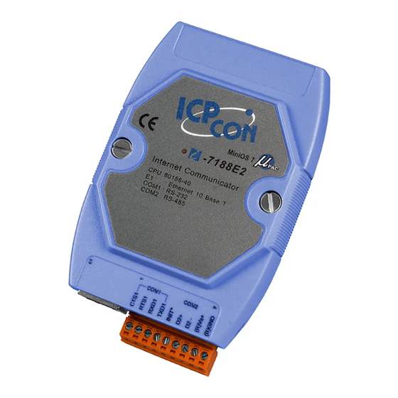
- Page 57 I-7188E2 Internet Communication Controller CPU 80188-40 : Ethernet 10 Base T COM1 : RS-232 COM2 : RS-485 COM1 COM 2 7188E Series Hardware User’s Manual, 2004, v2.2, 7MH-016-22 ----- 57...
- Page 58 2. The GND-signal of COM1 is shared with pin-9, GND. 3. Refer to Sec. 5.2 for wire connection of CA0910 to PC & 7188E 1. Refer to Sec. 5.5 for application wiring. 7188E Series Hardware User’s Manual, 2004, v2.2, 7MH-016-22 ----- 58...
- Page 59 (X507) i-7188E3 Internet Communication Controller CPU 80188-40 : Ethernet 10 Base T COM1 : RS-232 COM2 : RS-485 COM3 : RS-422/485 COM1 COM 2 7188E Series Hardware User’s Manual, 2004, v2.2, 7MH-016-22 ----- 59...
- Page 60 2. The GND-signal of COM1 is shared with pin-9, GND. 3. Refer to Sec. 5.2 for wire connection of CA0910 to PC & 7188E. 4. Refer to Sec. 5.5 for application wiring. 7188E Series Hardware User’s Manual, 2004, v2.2, 7MH-016-22 ----- 60...
- Page 61 (X508) I-7188E3-232 Internet Communication Controller CPU 80188-40 : Ethernet 10 Base T COM1 : RS-232 COM2 : RS-485 COM3 : RS-232 COM1 COM 2 7188E Series Hardware User’s Manual, 2004, v2.2, 7MH-016-22 ----- 61...
- Page 62 2. The GND-signal of COM1 is shared with pin-9, GND. 3. Refer to Sec. 5.2 for wire connection of CA0910 to PC & 7188E. 4. Refer to Sec. 5.5 for application wiring. 7188E Series Hardware User’s Manual, 2004, v2.2, 7MH-016-22 ----- 62...
- Page 63 (X504) i-7188E4 Internet Communication Controller CPU 80188-40 : Ethernet 10 Base T COM1 : RS-232 COM2 : RS-485 COM3~4 : RS-232 COM1 COM 2 7188E Series Hardware User’s Manual, 2004, v2.2, 7MH-016-22 ----- 63...
- Page 64 2. The GND-signal of COM1 is shared with pin-9, GND. 3. Refer to Sec. 5.2 for wire connection of CA0910 to PC & 7188E. 4. Refer to Sec. 5.5 for application wiring. 7188E Series Hardware User’s Manual, 2004, v2.2, 7MH-016-22 ----- 64...
- Page 65 (X505) i-7188E5 Internet Communication Controller CPU 80188-40 : Ethernet 10 Base T COM1 : RS-232 COM2 : RS-485 COM3~5 : RS-232 COM1 COM 2 7188E Series Hardware User’s Manual, 2004, v2.2, 7MH-016-22 ----- 65...
- Page 66 1. 7188E5/7188E5D does not support I/O Expansion Bus. So you cannot install any X???? into 7188E5/7188E5D. 2. The GND-signal of COM1 is shared with pin-9, GND. 3. Refer to Sec. 5.2 for wire connection of CA0910 to PC & 7188E. 7188E Series Hardware User’s Manual, 2004, v2.2, 7MH-016-22 ----- 66...
- Page 67 (X506) i-7188E8 Internet Communication Controller CPU 80188-40 : Ethernet 10 Base T COM1 : RS-232 COM2 : RS-485 COM3~8 : RS-232 COM1 COM 2 7188E Series Hardware User’s Manual, 2004, v2.2, 7MH-016-22 ----- 67...
- Page 68 2. The GND-signal of COM1 is shared with pin-9, GND. 3. Refer to Sec. 5.2 for wire connection of CA0910 to PC & 7188E. 4. Refer to Sec. 5.5 for application wiring. 7188E Series Hardware User’s Manual, 2004, v2.2, 7MH-016-22 ----- 68...
- Page 69 (X107) i-7188EA Embedded Internet/Ethernet Controller CPU 80188-40 : Ethernet 10 Base T COM1 : RS-232 COM2 : RS-485 DI:3.5V~30V DO:100mA, 30V max COM1 COM 2 7188E Series Hardware User’s Manual, 2004, v2.2, 7MH-016-22 ----- 69...
- Page 70 3. DI base address: 1. 4. DO base address: 0. 5. Refer to Sec. 5.2 7188E1 for wire connection of CA0910 to PC & 7188E. 6. Refer to Sec. 5.5 for application wiring. 7188E Series Hardware User’s Manual, 2004, v2.2, 7MH-016-22 ----- 70...
- Page 71 Embedded Internet/Ethernet Controller CPU 80188-40 : Ethernet 10 Base T COM1 : RS-232 COM2 : RS-485 10~23 : User Define I/O Pin COM1 COM 2 7188E Series Hardware User’s Manual, 2004, v2.2, 7MH-016-22 ----- 71...
- Page 72 2. The GND-signal of Com1 is shared with pin-9, GND. 3. Refer to Sec. 5.2 7188E1 for wire connection of CA0910 to PC & 7188E. 4. Refer to Sec. 5.5 for application wiring. 7188E Series Hardware User’s Manual, 2004, v2.2, 7MH-016-22 ----- 72...
-
Page 73: Specifications
Gives month and year, from 1980 to 2079 NVSRAM: 31 bytes, battery backup, data valid up to 10 years EEPROM 2048 bytes (8 blocks, each block has 256 bytes) Data retention > 100 years 1,000,000 erase/write cycles 7188E Series Hardware User’s Manual, 2004, v2.2, 7MH-016-22 ----- 73... - Page 74 2.0W for 7188EX-256 2.0W for 7188EXD-256 2.0W for 7188EA 3.0W for 7188EAD D/I/O: D/I: 6 channels, 3.5V ~ 30V max. Base address: 1 D/O: 7 channels, 100mA, 30V max. Base address: 0 7188E Series Hardware User’s Manual, 2004, v2.2, 7MH-016-22 ----- 74...
- Page 75 Communication speed: 115200 max. Directly connect to I7000 RS-485 network Display 7-segmemt LED: 5-digit (for 7188E1/2/3/4/5/8D) Power Power requirements: 10 to 30VDC(non-regulated) Power consumption: 2.0W for 7188E1/2/3/4/5/8 3.0W for 7188E1/2/3/4/5/8D 7188E Series Hardware User’s Manual, 2004, v2.2, 7MH-016-22 ----- 75...
- Page 76 Note1: RS-232, TXD, RXD, RTS, CTS, GND Note2: RS-232, TXD, RXD, GND Note3: RS-485, D2+, D2-; Self-tuner inside Note4: RS-232, TXD, RXD, RTS, CTS, GND, DCD, DTR, DSR, RI Note5: RS-422: TXD+, TXD-, RXD+, RXD- 7188E Series Hardware User’s Manual, 2004, v2.2, 7MH-016-22 ----- 76...
- Page 77 Operation system MiniOS7 MiniOS7 MiniOS7 MiniOS7 Programming TC, MSC, BC TC, MSC, BC TC, MSC, BC TC, MSC, BC language Program download I/O extension bus Ethernet interface 10M,10BaseT 10M,10BaseT 10M,10BaseT 7188E Series Hardware User’s Manual, 2004, v2.2, 7MH-016-22 ----- 77...
-
Page 78: Block Diagram
NVSRAM 80188-40 COM2 EEPROM watchdog timer RS-485 (2K) 16 bits timer I/O Expansion hardware serial no. 5-digit LED (7188EXD) (7188EXD-256) 10BaseT 7188EX +10V to +30V 7188EXD power converter 7188EX-256 7188EXD-256 7188E Series Hardware User’s Manual, 2004, v2.2, 7MH-016-22 ----- 78... - Page 79 Flash-ROM: 256K COM1 RS-232 COM2 RS-485 EEPROM 80188-40 for 7188E2(D) (2K) watchdog timer I/O Expansion 16 bits timer 5-digit LED (7188E1D) (7188E2D) 10BaseT +10V to +30V power converter 7188E1/7188E1D 7188E2/7188E2D 7188E Series Hardware User’s Manual, 2004, v2.2, 7MH-016-22 ----- 79...
- Page 80 Flash-ROM: 256K COM3 COM1 RS-422/RS-232 RS-232 COM4~8 COM2 RS-232 80188-40 RS-485 watchdog timer EEPROM (2K) I/O Expansion 16 bits timer D/I/O 5-digit LED (7188END) 10BaseT +10V to +30V 7188EN/7188END power converter 7188E Series Hardware User’s Manual, 2004, v2.2, 7MH-016-22 ----- 80...
-
Page 81: The Wire Connection Of 7188En Series
We welcome ODM X??? designs. Please send specifications to service@icpdas.com The wire connection of 7188E1 family is given as following: Ethernet 10M 7188E1 HOST COMPUTER RS-232 device Ethernet 10M To Ethernet Router 7188E1 RS-232 device 7188E Series Hardware User’s Manual, 2004, v2.2, 7MH-016-22 ----- 81... - Page 82 RS-232 device device DI*4 Ethernet 10M D0*4 7188E3 HOST COMPUTER RS-485 device RS-232 device DI*4 Ethernet 10M To Ethernet Router D0*4 7188E3 RS-485 device RS-422 device RS-485 RS-232 device device 7188E Series Hardware User’s Manual, 2004, v2.2, 7MH-016-22 ----- 82...
- Page 83 RS-232 device device RS-232 Ethernet 10M device 7188E4 HOST COMPUTER RS-232 device RS-232 device Ethernet 10M RS-232 device To Ethernet Router 7188E4 RS-485 device RS-232 device RS-485 RS-232 device device 7188E Series Hardware User’s Manual, 2004, v2.2, 7MH-016-22 ----- 83...
- Page 84 HOST COMPUTER device RS-232 device RS-232 device RS-232 device RS-232 device RS-232 Ethernet 10M device RS-232 device 7188E8 RS-485 RS-232 device device RS-232 device RS-232 device RS-485 RS-232 device device 7188E Series Hardware User’s Manual, 2004, v2.2, 7MH-016-22 ----- 84...
- Page 85 DI*4 Ethernet 10M 7188EX-256 D0*4 RS-232 device HOST COMPUTER X509 RS-232 device RS-232 device DI*4 Ethernet 10M 7188EX-256 D0*4 RS-485 RS-232 device device X509 RS-232 device RS-485 RS-232 device device 7188E Series Hardware User’s Manual, 2004, v2.2, 7MH-016-22 ----- 85...
- Page 86 H U B Ethernet 10M 7188E RS-232/485/422 fam ily devices Ethernet 10M 7188E RS-232/485/422 fam ily devices To Ethernet Router RS-232/485 7521/7522/7523 fam ily devices 7522A /7524/7527 RS-232/485/422 fam ily devices 7188E Series Hardware User’s Manual, 2004, v2.2, 7MH-016-22 ----- 86...
-
Page 87: Dimension And Mounting
Dimension and Mounting 5 . 5 0 3 . 9 0 . 9 1 5 . 2 5 1 . 7 2 7 . 8 5 7188E Series Hardware User’s Manual, 2004, v2.2, 7MH-016-22 ----- 87... - Page 88 Side View Back View Top View From View 7188E Series Hardware User’s Manual, 2004, v2.2, 7MH-016-22 ----- 88...
- Page 89 Stack Mounting Din-Rail Mounting 7188E Series Hardware User’s Manual, 2004, v2.2, 7MH-016-22 ----- 89...
Need help?
Do you have a question about the 7188E Series and is the answer not in the manual?
Questions and answers