ICP DAS USA CAN-8123 User Manual
Canopen slave device
Hide thumbs
Also See for CAN-8123:
- Quick start user manual (8 pages) ,
- User manual (195 pages) ,
- User manual (198 pages)
Table of Contents
Advertisement
Quick Links
CAN-8123/ CAN-8223/CAN-8423
CANopen Slave Device
Warranty
All products manufactured by ICP DAS are warranted
against defective materials for a period of one year from
the date of delivery to the original purchaser.
Warning
ICP DAS assume no liability for damages consequent
to the use of this product. ICP DAS reserves the right to
change this manual at any time without notice. The
information furnished by ICP DAS is believed to be
accurate and reliable. However, no responsibility is
assumed by ICP DAS for its use, nor for any infringements
of patents or other rights of third parties resulting from its
use.
Copyright
Copyright 2003 by ICP DAS. All rights are reserved.
Trademark
The names used for identification only maybe
registered trademarks of their respective companies.
CAN-8123/CAN-8223/CAN-8423 user manual (ver. 2.00, July/26/2007) ------1
User Manual
Advertisement
Table of Contents

Related Manuals for ICP DAS USA CAN-8123


Summary of Contents for ICP DAS USA CAN-8123
- Page 1 Copyright Copyright 2003 by ICP DAS. All rights are reserved. Trademark The names used for identification only maybe registered trademarks of their respective companies. CAN-8123/CAN-8223/CAN-8423 user manual (ver. 2.00, July/26/2007) ------1...
-
Page 2: Table Of Contents
Configuration with the CAN Slave Utility........54 CAN-8123/CAN-8223 Configuration (Off-line mode) ....59 CAN-8423 Configuration (On-line mode) ........66 CANopen Communication Set.............69 SDO Communication Set ............70 5.1.1 Upload SDO Protocol............70 5.1.2 SDO Block Upload............79 5.1.3 Download .................90 5.1.4 SDO Block Download............95 CAN-8123/CAN-8223/CAN-8423 user manual (ver. 2.00, July/26/2007) ------2... - Page 3 Error Control Protocol ..........166 Special Functions for CAN-8123/CAN-8223/CAN-8423...171 Object Dictionary of CAN-8123/CAN-8223/CAN-8423 ......179 Communication Profile Area.............179 Manufacturer Specific Profile Area ..........189 Standardized Device Profile Area ..........190 Appendix A: Dimensions................194 Appendix B: Analog I/O Transformation Table ........196 CAN-8123/CAN-8223/CAN-8423 user manual (ver. 2.00, July/26/2007) ------3...
-
Page 4: Introduction
Each expansion slot can plug in one I-87K or I-8000 series I/O module. For example, only one slot module can plug in the CAN-8123, and an CAN-8423 can have at most 4 slot modules plugged in it. All of these main control units follow the CANopen Spec DS-301 V4.01 and DSP-401 V2.1, and supplies... - Page 5 CAN-8123/CAN-8223/CAN-8423 user manual (ver. 2.00, July/26/2007) ------5...
-
Page 6: Hardware Features
CAN bus interface: ISO/IS 11898-2, 5-pin screw terminal with on-board optical isolators protection. Power Supply:20W, Unregulated +10VDC to +30VDC Operating Temperature:-25°C to +75°C Storage Temperature:-30°C to +85°C Humidity:5%~95% COM1 RS-232: TXD,RXD,RTS,CTS,GND Communication speed: 115200 bps. Configure tool connection CAN-8123/CAN-8223/CAN-8423 user manual (ver. 2.00, July/26/2007) ------6... -
Page 7: Can-8123/Can-8223/Can-8423 Features
1M bps Power LED, RUN LED, and ERR LED indicators Support max 4 I-8000 and I-87K series modules for CAN-8423 Provide a friendly Utility to configure the I-8000 and I-87K series modules CAN-8123/CAN-8223/CAN-8423 user manual (ver. 2.00, July/26/2007) ------7... -
Page 8: Utility Features
1.4 Utility Features Set the I-8000 and I-87K AI/AO modules parameters Show I-8000 and I-87K modules configuration Show Application and assembly object configurations Support IO connection path settings Support EDS file creation CAN-8123/CAN-8223/CAN-8423 user manual (ver. 2.00, July/26/2007) ------8... -
Page 9: Hardware Specification
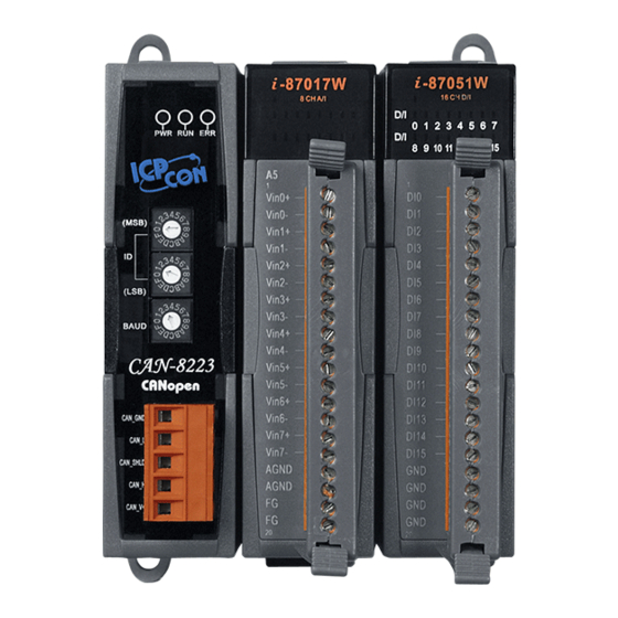
2 Hardware Specification 2.1 CAN-8123/CAN-8223 Hardware Structure CANopen Power LED Status LED Node ID and Baud rate rotary switch CAN Bus Connector 1 I/O Expansion Slot CAN-8123/CAN-8223/CAN-8423 user manual (ver. 2.00, July/26/2007) ------9... - Page 10 2 I/O Expansion Slots CAN-8123/CAN-8223/CAN-8423 user manual (ver. 2.00, July/26/2007) ------10...
-
Page 11: Can-8423 Hardware Structure
2.2 CAN-8423 Hardware Structure CANopen Status LED Node ID and Baud rate rotary switch Power LED RS-232 Port (connect to PC) Power Pin CAN Bus Connector 4 I/O Expansion Slots CAN-8123/CAN-8223/CAN-8423 user manual (ver. 2.00, July/26/2007) ------11... -
Page 12: Wire Connection
(meter) Cross Section Resistance (Ω) (Type) (mΩ/m) 0~40 0.25(23AWG)~ 124 (0.1%) 0.34mm (22AWG) 40~300 < 60 0.34(22AWG)~ 127 (0.1%) 0.6mm (20AWG) 300~600 < 40 0.5~0.6mm 150~300 (20AWG) 600~1K < 20 0.75~0.8mm 150~300 (18AWG) CAN-8123/CAN-8223/CAN-8423 user manual (ver. 2.00, July/26/2007) ------12... - Page 13 In the CAN-8123/CAN-8223/CAN-8423, the 120Ω terminal resistance is supplied. The JP2 for the CAN-8123/CAN-8223 is for terminal resistance. The JP2 location is shown in the following figure. CAN Connector Rotary Swtich Transciver CAN Controller 186 CPU I-8KCPS1/I-8KCPS2 Connector The JP1 on the CAN-8423 is used for adjusting terminal resistance, and its location is shown in the following figure.
- Page 14 10 K 5000 Note: When the bus length is greater than 1000m, the bridge or repeater devices may be needed. The pin assignment of both the CAN-8123/CAN-8223 and CAN-8423 CAN bus connectors are shown below. CAN_GND Pin 1 Pin 2...
-
Page 15: Power Led
CAN-8423 CAN bus connectors ping assignment 2.4 Power LED Power LED is yellow one. An CAN-8123/CAN-8223/CAN-8423 needs 10~30 VDC power input. The power consumption for an CAN-8123/CAN-8223/ CAN-8423 will correlate with the number of slot modules plugged into them. If the electronic power is enough, the Power LED will be turned on. -
Page 16: Canopen Status Led
Time (ms) CAN RUN LED State Description Single Flash Stopped The device is in Stopped state Blinking Pre-operational The device is in the pre-operational state Operational The device is in the operational state CAN-8123/CAN-8223/CAN-8423 user manual (ver. 2.00, July/26/2007) ------16... -
Page 17: Err Led
Guard messages). Each error event has different twinkling signal periods, and the signal periods and related meanings are displayed respectively in the following figure and table. Single Flash Double Flash Triple Flash 1200 1600 2000 1000 1400 1800 Time (ms) CAN-8123/CAN-8223/CAN-8423 user manual (ver. 2.00, July/26/2007) ------17... - Page 18 Note: If several errors are present at the same time, the error with the highest number will be indicated first. For example, if NMT Error (No. =3) and Sync Error (No. =4) occur, the SYNC error is indicated. CAN-8123/CAN-8223/CAN-8423 user manual (ver. 2.00, July/26/2007) ------18...
-
Page 19: Node Id And Baud Rate Rotary Switch
ID is set to exceed 127, the CANopen firmware will set the node ID to 1 automatically. For example, if the MSB rotary switch is turned to 3 and the LSB rotary switch is turned to 2, the CAN-8123/CAN-8223/CAN-8423 node ID is 0x32 and the decimal value is 50 (3*16+2=50). - Page 20 Since CAN-8123/CAN-8223 has no RS-232 COM Port, it is necessary to run the utility tool in the off-line mode if users want to get the EDS file of the CAN-8123/CAN-8223. Furthermore, when the CAN-8123/CAN-8223/CAN-8423 is started up, the CANopen firmware will check these rotary switches.
-
Page 21: Module Support
2.7 Module Support The CAN-8123/CAN-8223/CAN-8423 supports many kinds of DI, DO, AI and AO modules for the I-8000/I-87K series modules. When users want to apply these modules on the CANopen network, they only need to plug these modules into the CAN-8123/CAN-8223/CAN-8423 I/O expansion slots. Then, the CANopen firmware built in the CAN-8123/CAN-8223/CAN-8423 will search for them by organizing the corresponding CANopen entries automatically. -
Page 22: Canopen System
The functions and general concepts for each part are shown as follows. Object Communication Application Dicitionary State Application mechanism objcet Entry 1 Entry 2 Comm. Application objcet objcet Comm. objcet Entry n Comm. Application objcet objcet Bus System Process CAN-8123/CAN-8223/CAN-8423 user manual (ver. 2.00, July/26/2007) ------22... - Page 23 CANopen specification uses the 4-bit function code and 7-bit node ID to combine the 11-bit ID of CAN message, and name it as communication object ID (COB-ID). The COB-ID structure is displayed below. bit 10 bit 0 Function Code Node ID CAN-8123/CAN-8223/CAN-8423 user manual (ver. 2.00, July/26/2007) ------23...
- Page 24 The following list shows these reversed COB-IDs. Reversed COB-ID (Hex) Used by object Reserved SYNC 81~FF EMERGENCY TIME STAMP 101~180 reversed 581~5FF Default Transmit-SDO 601~67F Default Receive-SDO reversed 701~77F NMT Error Control 780~7FF reversed CAN-8123/CAN-8223/CAN-8423 user manual (ver. 2.00, July/26/2007) ------24...
- Page 25 Node ID SDO for transmission (TxSDO) 1100 Node ID SDO for reception (RxSDO) 1110 Node ID NMT Error Control Note: For the CAN-8123/CAN-8223/CAN-8423, we provide all communication objects except for the TIME STAMP. CAN-8123/CAN-8223/CAN-8423 user manual (ver. 2.00, July/26/2007) ------25...
- Page 26 0x6411. When the CANopen device obtains the input value, these values are stored in the 0x6000 and 0x6401 indexes. Furthermore, the values stored in the 0x6200 and 0x6411 indexes also output to the DO and AO channels. The basic concept is depicted as follows. CAN-8123/CAN-8223/CAN-8423 user manual (ver. 2.00, July/26/2007) ------26...
- Page 27 Take the CAN-8423 for example. There are some I-8000 or I-87K series modules plugged in the CAN-8423 I/O expansion slots. The related information for each module is shown below. Module Name Slot No DO (ch) AO (ch) DI (ch) AI (ch) I-8063 I-87053 I-8053 CAN-8123/CAN-8223/CAN-8423 user manual (ver. 2.00, July/26/2007) ------27...
- Page 28 CAN-8423 will go to the next slot number to continue. Each analog channel is stored by using 2 bytes. The number of digital channels of one module, which can’t be divided by 8 with no remainder, is stored with 1 byte. CAN-8123/CAN-8223/CAN-8423 user manual (ver. 2.00, July/26/2007) ------28...
- Page 29 The application objects handle all of the device functionalities, which respect to the interaction with the process environment. It is the bridge between the object dictionary and practical process, such as the analog I/O, digital I/O…. CAN-8123/CAN-8223/CAN-8423 user manual (ver. 2.00, July/26/2007) ------29...
-
Page 30: Sdo Introduction
The SDO has two kinds of the COB-IDs, which are RxSDOs and TxSDOs. They are viewed at point in the CANopen device. For example, from the view of the CAN-8123/CAN-8223/CAN-8423, if users want to send a SDO message, then the CAN-8123/CAN-8223/CAN-8423 needs to receive the SDO message transmitted from users. - Page 31 SDO server object dictionary which uses the read-only access type, then the abort SDO transfer protocol will be given and the SDO transmission will also stop. The CAN-8123/CAN-8223/CAN-8423 only supports the SDO server. Therefore, it can only be passive and wait for the client requirements. The general...
-
Page 32: Pdo Introduction
PDO consumers need to send out a remote transmit request to the PDO producer. According to this remote request message, the PDO producer responds the corresponding PDO message for each PDO consumer in the CAN bus. The PDO communication structure figure is shown below. CAN-8123/CAN-8223/CAN-8423 user manual (ver. 2.00, July/26/2007) ------32... - Page 33 CAN-8123/CAN-8223/CAN-8423, it needs to use the RxPDO COB-ID of the CAN-8123/CAN-8223/CAN-8423 because it is a PDO reception action viewed from the CAN-8123/CAN-8223/CAN-8423. Inversely, when some PDO consumers send remote transmit requests to the CAN-8123/CAN-8223/ CAN-8423, it must use the TxPDO COB-ID of the CAN-8123/CAN-8223/ CAN-8423 because it is a PDO transmission action viewed from the CAN-8123/CAN-8223/CAN-8423.
- Page 34 PDO transmissions are also triggered by the occurrence of a specific event for the device or if a specified time has elapsed without the occurrence of an event. For example, the PDO transmission of the CAN-8123/CAN-8223/ CAN-8423 can be triggered by the event timer of the PDO communication parameters, which is set by the user.
- Page 35 TxPDO message to the CANopen PDO consumers. For the RxPDO object, the CAN-8123/CAN-8223/CAN-8423 needs to receive the SYNC objects to actuate the RxPDO object, which is received before the SYNC object. The following figures indicate how the acyclic synchronous transmission type works on the RxPDO and the TxPDO.
- Page 36 3 SYNC objects, the CAN-8123/CAN-8223/CAN-8423 will feed back the TxPDO object after receiving 3 SYNC object. For the RxPDO, actuating the DO/AO channels by the RxPDO is independent of the number of SYNC objects. These concepts are shown in the figures below.
- Page 37 The RTR-only synchronous mode is activated when receiving a remote-transmit-request message and SYNC objects. This transmission type is only useful for TxPDO. In this situation, the CAN-8123/CAN-8223/CAN-8423 will update the DI/AI value when receiving the SYNC object. And, if the RTR object is received, the CAN-8123/CAN-8223/CAN-8423 will respond to the TxPDO object.
- Page 38 The other part of the asynchronous mode is the asynchronous transmission type. Under this transmission type, the TxPDO message can be triggered not only by receiving the RTR object but also by the occurrence of CAN-8123/CAN-8223/CAN-8423 user manual (ver. 2.00, July/26/2007) ------38...
- Page 39 CAN-8123/CAN-8223/CAN-8423 boots up. The concept of the asynchronous type is illustrated as follows. Inhibit Time Because of the arbitration mechanism of the CAN bus, the smaller CANopen communication object ID has a higher transmission priority than the bigger one.
- Page 40 There shall be up to 4 enabled TxPDO mapping objects and up to 4 RxPDO mapping objects with default mappings. 1st RxPDO and TxPDO mappings are used for digital outputs and inputs to each other. CAN-8123/CAN-8223/CAN-8423 user manual (ver. 2.00, July/26/2007) ------40...
- Page 41 CAN-8123/CAN-8223/CAN-8423, the first 8 DO object entries will be mapped to the first RxPDO mapping object because one DO object entry needs one byte space. The last 3 DO object entries will be assigned into the 5th RxPDO because of the 2nd and 3rd rule described above.
- Page 42 TxPDO message refer to the AI channel 0 value. The fifth and sixth bytes are the values link to AI channel 1. The relationships among the object dictionary, the PDO mapping object and the PDO message are given below. CAN-8123/CAN-8223/CAN-8423 user manual (ver. 2.00, July/26/2007) ------42...
- Page 43 Practical I/O Object Dictionary TxPDO mapping objects RxPDO mapping objects TxPDO RxPDO CAN-8123/CAN-8223/CAN-8423 user manual (ver. 2.00, July/26/2007) ------43...
-
Page 44: Emcy Introduction
Manufacturer specific Error Field All the fields in the emergency object data will be described in section 5.3. Take the CAN-8123/CAN-8223/CAN-8423 for an example, if any errors occur in the CAN-8123/CAN-8223/CAN-8423, the EMCY message will be sent out from the CAN-8123/CAN-8223/CAN-8423. Afterwards, the EMCY message will not be transmitted again if the same error occurs repeatedly. -
Page 45: Nmt Introduction
The error control protocol gives the user the way to detect the remote error in the network. It can confirm if the node still lives or not. CAN-8123/CAN-8223/CAN-8423 user manual (ver. 2.00, July/26/2007) ------45... -
Page 46: Module Control Protocols
At “Power on” the initialization state is entered autonomously Initialization finished enter Pre-Operational automatically (3),(6) “Start Remote Node” indication (4),(7) “Enter Pre-Optional State” indication (5),(8) “Stop Remote Node” indication “Reset Node” or “Reset Communication” indication CAN-8123/CAN-8223/CAN-8423 user manual (ver. 2.00, July/26/2007) ------46... -
Page 47: Error Control Protocols
According to the CANopen spec, one device is not allowed to use both error control mechanisms, Guarding Protocol and Heartbeat Protocol, at the same time. The CAN-8123/CAN-8223/CAN-8423 provides the salve function of the Node Guarding Protocol. Therefore, users can only use this protocol for the CAN-8123/CAN-8223/CAN-8423 in practical application. - Page 48 0x6443 can control the error mode value of the DO or AO channels to enable or disable when the “Lift Guarding Event” has been indicated. For more information about objects with index 0x6206, 0x6207, 0x6443, and 0x6444, please refer to chapter 6. CAN-8123/CAN-8223/CAN-8423 user manual (ver. 2.00, July/26/2007) ------48...
-
Page 49: Configuration & Getting Start
4 Configuration & Getting Start 4.1 CAN-8123/CAN-8223 Configuration Flowchart CAN-8123/CAN-8223/CAN-8423 user manual (ver. 2.00, July/26/2007) ------49... - Page 50 The following procedure is the general concept for off-line mode. This procedure can be applied in the both of the CAN-8123/CAN-8223 and CAN-8423. CAN-8123/CAN-8223/CAN-8423 user manual (ver. 2.00, July/26/2007) ------50...
-
Page 51: Can-8423 Configuration Flowchart
4.2 CAN-8423 Configuration Flowchart CAN-8123/CAN-8223/CAN-8423 user manual (ver. 2.00, July/26/2007) ------51... - Page 52 The following procedure is the general concept for on-line mode. This procedure can be only applied in the CAN-8423. CAN-8123/CAN-8223/CAN-8423 user manual (ver. 2.00, July/26/2007) ------52...
-
Page 53: Can Slave Utility Overview
CAN-8423 EDS file creation with on-line mode, That is to say that users can turn on the CAN-8123/CAN-8223/CAN-8423 and directly apply it in the CANopen network. If the EDS file is necessary, users can get the EDS file by using CAN Slave Utility. -
Page 54: Configuration With The Can Slave Utility
CD-ROM disk following the path of “CD:\CANopen\Slave\CAN-8x23\Utility\”. Step 2: Execute the CAN_SL_Setup.exe file to install the CAN Slave Utility. Step 3: A “Welcome” window pops up to prompt user to begin installation. CAN-8123/CAN-8223/CAN-8423 user manual (ver. 2.00, July/26/2007) ------54... - Page 55 Step 5: Click the “Next” button and start to install the CAN Slave Utility to the system. After finishing the process, the following figure will be displayed prompting users to “OK” the successful completion of the installation. CAN-8123/CAN-8223/CAN-8423 user manual (ver. 2.00, July/26/2007) ------55...
- Page 56 Step 6: After finishing the installation of the CAN Slave Utility, users can find the CAN_SL Utility as shown in the following screenshot. CAN-8123/CAN-8223/CAN-8423 user manual (ver. 2.00, July/26/2007) ------56...
- Page 57 Step 1: Click “Start” in the task bar, then click Setting/Control Panel as shown in the following figure. Step 2: Click the “Add/Remove” button Programs icon to open the dialog. CAN-8123/CAN-8223/CAN-8423 user manual (ver. 2.00, July/26/2007) ------57...
- Page 58 Step 3: Find out the CAN_SL Utility, and click the Change/Remove button. Step 4: Click the button “Yes” button to remove the software. Step 5: Finally, click the button “OK” button to finish the uninstall process. CAN-8123/CAN-8223/CAN-8423 user manual (ver. 2.00, July/26/2007) ------58...
-
Page 59: Can-8123/Can-8223 Configuration (Off-Line Mode)
123 and baud rate 1000Kbps. Fill the correct value of users’ CAN-8223 node ID and baud in the “NODE ID” and “CAN Baud rate” filed. Then, select the “Slot Number” to “2 Slot”. CAN-8123/CAN-8223/CAN-8423 user manual (ver. 2.00, July/26/2007) ------59... - Page 60 Step 4: If the I-8024 and I-8042 modules are plugged into slot 0 and slot 1 respectively, then, select 8024 in the list box, and click button “Apply Module” to save the configuration. CAN-8123/CAN-8223/CAN-8423 user manual (ver. 2.00, July/26/2007) ------60...
- Page 61 Step 6: Afterwards, repeat the step 4~5 to configure the slot 1 to I-8042 module. Then, click “Save Setting” button to finish the off-line parameter settings. CAN-8123/CAN-8223/CAN-8423 user manual (ver. 2.00, July/26/2007) ------61...
- Page 62 Also, users can check the default settings for each slot module by clicking this module. Or move the mouse pointer on the slot module to see the module name and module information in the “Module Information” frame. CAN-8123/CAN-8223/CAN-8423 user manual (ver. 2.00, July/26/2007) ------62...
- Page 63 Step 9: Users can click on the “PDO Information”, “Device Information “, and the “Slot Module Information” button to view the PDO objects, device profile and slot module configuration information. These information dialogs are shown below. CAN-8123/CAN-8223/CAN-8423 user manual (ver. 2.00, July/26/2007) ------63...
- Page 64 If everything is ok, click the “Finish” button to create the EDS file. CAN-8123/CAN-8223/CAN-8423 user manual (ver. 2.00, July/26/2007) ------64...
- Page 65 EEPROM. It may cause the mismatch between real input/output range setting and EDS file. By the way, CAN-8123/CAN-8223 needs to configure the input/output range settings by using CANopen SDO protocol. For more detail, please refer to the section 5.5 in CAN-8123/CAN-8223/CAN-8423 user manual.
-
Page 66: Can-8423 Configuration (On-Line Mode)
Step 2: Use the “Baud” rotary switch again to set the baud rate of CAN-8423. Here, use baud rate 1000Kbps for the demo. Therefore, set the “Baud” rotary switch to 7. BAUD Step 3: Execute the CAN_SL.exe file, and the figure will be displayed. Select a CAN-8123/CAN-8223/CAN-8423 user manual (ver. 2.00, July/26/2007) ------66... - Page 67 Step 5: Click the slot module 3 and select the output range in the list box of “Module Configuration” frame. Here, select -10.00V~+10.00V for demo. Because the feature of I-8024 slot module, each channel output range will be changed together after users select the output range of one channel. CAN-8123/CAN-8223/CAN-8423 user manual (ver. 2.00, July/26/2007) ------67...
- Page 68 For the detail information, please refer to the Step8 and Setp9 in section 4.5. Note: The CAN-8423 can also create the EDS file by using off-line mode, and set the analog input range or analog output range by using the CANopen SDO protocol. CAN-8123/CAN-8223/CAN-8423 user manual (ver. 2.00, July/26/2007) ------68...
-
Page 69: Canopen Communication Set
In the following section, several CANopen communication protocols are described. Each protocol description has one corresponding demo. Because the communication methods in the CAN-8123/CAN-8223 are similar with the ones in CAN-8423, therefore only the demo for CAN-8423 is given. Before starting the demo, users must have one CAN interface to send out the CAN command. -
Page 70: Sdo Communication Set
SDO upload protocol. That is to say, if the data upload is less enough to be transmitted in the initiate SDO upload protocol, then the upload SDO segment protocol will not be used. The communication method of this protocol is shown as follows. CAN-8123/CAN-8223/CAN-8423 user manual (ver. 2.00, July/26/2007) ------70... - Page 71 : not used, always 0 reserved : reserved for further use , always 0 CAN-8123/CAN-8223/CAN-8423 user manual (ver. 2.00, July/26/2007) ------71...
- Page 72 When the upload data length exceeds 4 bytes, the upload SDO segment protocol is needed. After finishing the transmission of the initiate SDO upload protocol, the SDO client starts to upload the data, and the upload segment protocol will follow the process shown below. CAN-8123/CAN-8223/CAN-8423 user manual (ver. 2.00, July/26/2007) ------72...
- Page 73 Bytes [8-n, 7] do not contain segment data. n = 0 if no segment size is indicated. : not used, always 0 reserved : reserved for further use , always 0 CAN-8123/CAN-8223/CAN-8423 user manual (ver. 2.00, July/26/2007) ------73...
- Page 74 0x1400 with sub-index 00. Also, users can get the string located in the object with index 0x1008 by using the initiate SDO upload protocol and the upload SDO segment protocol. CAN-8123/CAN-8223/CAN-8423 user manual (ver. 2.00, July/26/2007) ------74...
- Page 75 Func Code Node ID Length SDO server SDO client (CAN-8123/CAN-8223 /CAN-8423) 00 14 00 02 00 00 00 Because the n=3, only the 4th byte is valid. Therefore, the feedback value is 02. CAN-8123/CAN-8223/CAN-8423 user manual (ver. 2.00, July/26/2007) ------75...
- Page 76 Therefore, the data “09 00 00 00” means that users will upload 9 bytes data from CAN-8423. Step 3. Request the CAN-8123 to start the data transmission. CAN-8123/CAN-8223/CAN-8423 user manual (ver. 2.00, July/26/2007) ------76...
- Page 77 Users can check chapter 6 to see that the object entry with index 0x1008 and sub index 00 has the data type “VISIBLE_STRING”. Therefore, users need to transfer these data values to the corresponding ASCII character. After transformation, they are “CAN-842”. CAN-8123/CAN-8223/CAN-8423 user manual (ver. 2.00, July/26/2007) ------77...
- Page 78 33 00 00 00 00 00 00 seg-data Because the n=5, only the fisrt two bytes are valid. Transfer the value of 0x33 and 0x00 to the corresponding ASCII character. After transformation, it means “3 ”. CAN-8123/CAN-8223/CAN-8423 user manual (ver. 2.00, July/26/2007) ------78...
-
Page 79: Sdo Block Upload
Initiate SDO Block Upload Protocol The SDO Block Upload is usually used for large data transmission. At the beginning of the SDO Block Upload, the Initiate SDO Block Upload protocol is needed. This protocol is described below. CAN-8123/CAN-8223/CAN-8423 user manual (ver. 2.00, July/26/2007) ------79... - Page 80 LSB and byte 7 is the MSB. : number of segments per block with 0 < blksize < 128 blksize : not used, always 0 reserved : reserved for further use , always 0 CAN-8123/CAN-8223/CAN-8423 user manual (ver. 2.00, July/26/2007) ------80...
- Page 81 Upload SDO Block Segment protocol. The SDO server can send a maximum of 127 blocks by using 127 Upload SDO Block Segment protocols. Here is the structure of the Upload SDO Block Segment protocol. CAN-8123/CAN-8223/CAN-8423 user manual (ver. 2.00, July/26/2007) ------81...
- Page 82 : number of segments per block that has to be used by server for blksize the following block upload with 0 < blksize < 128 : not used, always 0 reserved : reserved for further use , always 0 CAN-8123/CAN-8223/CAN-8423 user manual (ver. 2.00, July/26/2007) ------82...
- Page 83 End SDO Block Upload Protocol The End SDO Block Upload protocol is used for finishing the SDO Block upload, and is shown in the following figure. CAN-8123/CAN-8223/CAN-8423 user manual (ver. 2.00, July/26/2007) ------83...
- Page 84 The algorithm for generating the CRC is as follows. x^16+x^12+x^5+1 CRC is only valid if in Initiate Block Upload cc and sc are set to Otherwise CAN-8123/CAN-8223/CAN-8423, it is not support CRC check mechanism. : not used, always 0 reserved : reserved for further use , always 0...
- Page 85 SDO Block Upload Example The following figure indicates the general procedure for applying the SDO Block upload. CAN-8123/CAN-8223/CAN-8423 user manual (ver. 2.00, July/26/2007) ------85...
- Page 86 8-byte Data (byte) Func Code Node ID Length SDO server SDO client (CAN-8x23) 08 10 00 09 00 00 00 size The CAN-8123 will response 9 bytes data during the SDO Block Upload. CAN-8123/CAN-8223/CAN-8423 user manual (ver. 2.00, July/26/2007) ------86...
- Page 87 Func Code Node ID Length SDO server SDO client (CAN-8x23) Step 4. The CAN-8123 responds to the first 7 bytes of data by using the Upload SDO Block Segment protocol. 11-bit COB-ID (bit) Data 8-byte Data (byte) Func Code Node ID...
- Page 88 Because this segment is the last one, not all of the data in the seg-data filed is useful. The valid data length will be indicated when the CAN-8123 send a message to finish the Block Upload protocol. Please refer to the value of n in the step 7.
- Page 89 00 00 Step 8. Users send a message to finish the End SDO Block Upload protocol. 11-bit COB-ID (bit) 8-byte Data (byte) Data Func Code Node ID Length SDO server SDO client (CAN-8x23) CAN-8123/CAN-8223/CAN-8423 user manual (ver. 2.00, July/26/2007) ------89...
-
Page 90: Download
If the download data length is less than 4 bytes, the download action will finish in the download initialization protocol. Or, the download segment protocol will be needed. These two protocols are shown below. CAN-8123/CAN-8223/CAN-8423 user manual (ver. 2.00, July/26/2007) ------90... - Page 91 : not used, always 0 reserved : reserved for further use , always 0 CAN-8123/CAN-8223/CAN-8423 user manual (ver. 2.00, July/26/2007) ------91...
- Page 92 The first segment will have the toggle-bit set to 0. The toggle bit will be equal for the request and the response message. : not used, always 0 reserved : reserved for further use , always 0 CAN-8123/CAN-8223/CAN-8423 user manual (ver. 2.00, July/26/2007) ------92...
- Page 93 Since all of those object entries, which can be written, in the CAN-8123/CAN-8223/CAN-8423 are equal or less than 4 bytes, we can only provide the demo for expedited transfer. CAN-8123/CAN-8223/CAN-8423 user manual (ver. 2.00, July/26/2007) ------93...
- Page 94 Afterwards, users can use upload methods mentioned before to read back the value for confirmation. 11-bit COB-ID (bit) 8-byte Data (byte) Data Func Code Node ID Length SDO server SDO client (CAN-8123/CAN-8223/ CAN-8423) 00 14 00 CAN-8123/CAN-8223/CAN-8423 user manual (ver. 2.00, July/26/2007) ------94...
-
Page 95: Sdo Block Download
After finishing the data transmission, the client and server will use the End SDO Block protocol to terminate the SDO Block Download. The following figures are the structures for the three protocols. Initiate SDO Block Download Protocol CAN-8123/CAN-8223/CAN-8423 user manual (ver. 2.00, July/26/2007) ------95... - Page 96 4 contains the LSB and byte 7 is the MSB. : number of segments per block with 0 < blksize < 128 blksize : not used, always 0 reserved : reserved for further use , always 0 CAN-8123/CAN-8223/CAN-8423 user manual (ver. 2.00, July/26/2007) ------96...
- Page 97 : number of segments per block that has to be used by client for blksize the following block download with 0 < blksize < 128 : not used, always 0 reserved : reserved for further use , always 0 CAN-8123/CAN-8223/CAN-8423 user manual (ver. 2.00, July/26/2007) ------97...
- Page 98 The algorithm for generating the CRC is as follows. x^16+x^12+x^5+1 CRC is only valid if in Initiate Block Download cc and sc are set Otherwise, CAN-8123/CAN-8223/CAN-8423, it is not support CRC check mechanism. : not used, always 0 reserved : reserved for further use , always 0...
- Page 99 In this demo, the value of the object entry with index 0x1400 and sub-index 0x02 will be changed to 5 by using the SDO Block Download communication method. When the SDO Block Download is running, the procedure is as follows. CAN-8123/CAN-8223/CAN-8423 user manual (ver. 2.00, July/26/2007) ------99...
- Page 100 Block Download protocol. Afterwards, the SDO client can start to download the object‘s data with index 0x1400 and sub-index 02 to CAN-8423. 11-bit COB-ID (bit) Data 8-byte Data (byte) Func Code Node ID Length SDO server SDO client (CAN-8123/CAN-8223/ CAN-8423) 00 14 02 blksize CAN-8123/CAN-8223/CAN-8423 user manual (ver. 2.00, July/26/2007) ------100...
- Page 101 If not, this block needs to be transmitted again. After finishing the data transmission, the Download SDO Block Segment protocol is terminated. 11-bit COB-ID (bit) 8-byte Data (byte) Data Func Code Node ID Length SDO server SDO client (CAN-8123/CAN-8223/ CAN-8423) ackseq blksize CAN-8123/CAN-8223/CAN-8423 user manual (ver. 2.00, July/26/2007) ------101...
- Page 102 Step 6. The CAN-8423 responds to the message to terminate the End SDO Block Download protocol. 11-bit COB-ID (bit) Data 8-byte Data (byte) Func Code Node ID Length SDO server SDO client (CAN-8123/CAN-8223/ CAN-8423) CAN-8123/CAN-8223/CAN-8423 user manual (ver. 2.00, July/26/2007) ------102...
-
Page 103: Abort Sdo Transfer Protocol
: command specifier 4: abort transfer request : not used, always 0 : multiplexer It represents index and sub-index of the SDO : contains a 4-byte “Abort Code” about the reason for the abort CAN-8123/CAN-8223/CAN-8423 user manual (ver. 2.00, July/26/2007) ------103... - Page 104 0800 0022h the present device state. Object dictionary dynamic generation fails or no object dictionary is 0800 0023h present (e.g. object dictionary is generated from file and generation fails because of an file error). CAN-8123/CAN-8223/CAN-8423 user manual (ver. 2.00, July/26/2007) ------104...
- Page 105 The object index 0x1008 doesn’t have the sub-index 01 entry. Therefore, if users read the object entry with index 0x1008 and sub-index 01, the CAN-8123/CAN-8223/CAN-8423 will response the Abort SDO Transfer message. We will also use this point as a demo to follow.
-
Page 106: Pdo Communication Set
No RTR allowed on this PDO 11-bit ID (CAN 2.0A) 29-bit ID (CAN 2.0B) 28-11 If bit 29=0 If bit 29=1: 28-11 bits of 29-bit COB-ID 10-0 (LSB) 10-0 bits of COB-ID Note: CAN-8123/CAN-8223/CAN-8423 only supports CAN 2.0A. CAN-8123/CAN-8223/CAN-8423 user manual (ver. 2.00, July/26/2007) ------106... - Page 107 3.1. When users want to define the COB-ID, it is important to avoid the conflict with the COB-ID used in the same node. 2. The PDO COB-ID parameters cannot be changed if the PDO is valid (bit 31 =0). CAN-8123/CAN-8223/CAN-8423 user manual (ver. 2.00, July/26/2007) ------107...
-
Page 108: Transmission Type
TxPDO. The PDO, which includes the DI value, will be sent when the DI value is changed. For the RxPDO, both of these two types mean that receiving the RxPDO will directly trigger an update of the mapped data. CAN-8123/CAN-8223/CAN-8423 user manual (ver. 2.00, July/26/2007) ------108... -
Page 109: Pdo Communication Rule
Besides, PDO communications can be only applied in the NMT operational state. Users can use the NMT module control protocol to change the NMT state of the CAN-8123/CAN-8223/CAN-8423. It is described in section 5.3. Incidentally, during communication via the PDO messages, the data length of the PDO message must match with the PDO mapping object. - Page 110 : the defautl PDO COB-ID, or the PDO COB-ID defined by user COB-ID : the data length about how many bytes the PDO message has PDO-msg : the real-time data or the data which can be mapped into the PDO mapping objects CAN-8123/CAN-8223/CAN-8423 user manual (ver. 2.00, July/26/2007) ------110...
- Page 111 125Kbps. Use CAN Slave Utility to set the I-8024 and I-87017 input/output range to -10V~+10V. During using the CAN Slave Utility, the following information can be seen. (CAN-8123/CAN-8223 can’t use the on-line mode to set the channel input/output range. Therefore, users can refer to section 5.5 to know how to use the SDO protocol to set the channel...
- Page 112 The function of the acyclic and synchronous TxPDO. The function of the cyclic and synchronous TxPDO. The function of the synchronous and RTR-only TxPDO. The function of the asynchronous and RTR-only RxPDO. Dynamic PDO mapping for DI/AI/DO/AO channels CAN-8123/CAN-8223/CAN-8423 user manual (ver. 2.00, July/26/2007) ------112...
- Page 113 CAN-8423 first, because the PDO communication can only run under the NMT Operational state. 11-bit COB-ID (bit) 8-byte Data (byte) Data Func Code Node ID Length NMT slave NMT master (CAN-8123/CAN-8223/ CAN-8423) Node ID CAN-8123/CAN-8223/CAN-8423 user manual (ver. 2.00, July/26/2007) ------113...
- Page 114 RxPDO contains only two bytes. According to the PDO mapping table shown above, the first byte is the DO0~DO7 channel values of the I-8057. The second byte is the DO8~DO15 channel values of the I-8057. CAN-8123/CAN-8223/CAN-8423 user manual (ver. 2.00, July/26/2007) ------114...
- Page 115 DI value is 1 if the DI is OFF, because of the character of the I-8053 DI channels. Therefore, the first byte indicates that the DI2, DI4, and DI5 of the I-8053 are ON. The second byte shows that the DI9 and DI12 of the I-8053 are ON. CAN-8123/CAN-8223/CAN-8423 user manual (ver. 2.00, July/26/2007) ------115...
- Page 116 “3F”. All the other AI channels are set to 0V, therefore, give value “00 00” for these channels. For more details about how to transfer the value between the hex and float, please refer to section 6.3. CAN-8123/CAN-8223/CAN-8423 user manual (ver. 2.00, July/26/2007) ------116...
- Page 117 0x8000 (-32768) to 0x7FFF (32767). The value 0x4000 (16384) can be transferred by using the following equation. ⎛ ⎞ − − 16384 32768 ⎜ ⎜ ∗ ⎟ ⎟ − − − FloatValue − − ⎝ ⎠ 32767 32768 ≈ CAN-8123/CAN-8223/CAN-8423 user manual (ver. 2.00, July/26/2007) ------117...
- Page 118 Step 7. The CAN-8423 will response the message to finish the data download. 11-bit COB-ID (bit) Data 8-byte Data (byte) Func Code Node ID Length SDO server SDO client (CAN-8123/CAN-8223/ CAN-8423) 00 18 05 CAN-8123/CAN-8223/CAN-8423 user manual (ver. 2.00, July/26/2007) ------118...
- Page 119 CAN-8423) 0x281 COB-ID 06 40 FF FF FF FF FF FF PDO-msg The value of 0x4006 is equal to 5.002V. The AI value is changed because of the noise disturbance or other factors. CAN-8123/CAN-8223/CAN-8423 user manual (ver. 2.00, July/26/2007) ------119...
- Page 120 Step 11. Set the event timer to 0 to finish the event timer test. 11-bit COB-ID (bit) Data 8-byte Data (byte) Func Code Node ID Length SDO server SDO client (CAN-8123/CAN-8223/ CAN-8423) 00 18 05 00 00 00 00 CAN-8123/CAN-8223/CAN-8423 user manual (ver. 2.00, July/26/2007) ------120...
- Page 121 11-bit COB-ID (bit) Data 8-byte Data (byte) Func Code Node ID Length SDO server SDO client (CAN-8123/CAN-8223/ CAN-8423) 00 18 05 CAN-8123/CAN-8223/CAN-8423 user manual (ver. 2.00, July/26/2007) ------121...
- Page 122 Node ID Length SDO server SDO client (CAN-8123/CAN-8223/ CAN-8423) 00 14 02 11-bit COB-ID (bit) 8-byte Data (byte) Data Func Code Node ID Length SDO server SDO client (CAN-8123/CAN-8223/ CAN-8423) 00 14 02 CAN-8123/CAN-8223/CAN-8423 user manual (ver. 2.00, July/26/2007) ------122...
- Page 123 CAN-8423) 0x80 COB-ID The message of the SYNC object is always fixed as the format described above. The COB-ID of the SYNC object can be changed arbitrarily. It follows the producer/consumer relationship. CAN-8123/CAN-8223/CAN-8423 user manual (ver. 2.00, July/26/2007) ------123...
- Page 124 Step 16. Set the transmission type of the 1st RxPDO to 255 to finish the test. 11-bit COB-ID (bit) 8-byte Data (byte) Data Func Code Node ID Length SDO server SDO client (CAN-8123/CAN-8223/ CAN-8423) 00 14 02 FF 00 00 00 CAN-8123/CAN-8223/CAN-8423 user manual (ver. 2.00, July/26/2007) ------124...
- Page 125 11-bit COB-ID (bit) Data 8-byte Data (byte) Func Code Node ID Length SDO server SDO client (CAN-8123/CAN-8223/ CAN-8423) 00 14 02 CAN-8123/CAN-8223/CAN-8423 user manual (ver. 2.00, July/26/2007) ------125...
- Page 126 SDO server SDO client (CAN-8123/CAN-8223/ CAN-8423) 00 18 02 00 00 00 00 11-bit COB-ID (bit) Data 8-byte Data (byte) Func Code Node ID Length SDO server SDO client (CAN-8123/CAN-8223/ CAN-8423) 00 18 02 CAN-8123/CAN-8223/CAN-8423 user manual (ver. 2.00, July/26/2007) ------126...
- Page 127 0. The SYNC message is needed to trigger the action of the 1st TxPDO. 11-bit COB-ID (bit) Data 8-byte Data (byte) Func Code Node ID Length SYNC consumer SYNC (CAN-8123/CAN-8223/ producer CAN-8423) 0x80 COB-ID CAN-8123/CAN-8223/CAN-8423 user manual (ver. 2.00, July/26/2007) ------127...
- Page 128 0 and 1. At transmission type 1, the TxPDO is always transmitted no matter whether the DI values are changed or not, when the CAN-8423 receives the SYNC object. CAN-8123/CAN-8223/CAN-8423 user manual (ver. 2.00, July/26/2007) ------128...
- Page 129 SDO server SDO client (CAN-8123/CAN-8223/ CAN-8423) 00 18 02 03 00 00 00 11-bit COB-ID (bit) 8-byte Data (byte) Data Func Code Node ID Length SDO server SDO client (CAN-8123/CAN-8223/ CAN-8423) 00 18 02 CAN-8123/CAN-8223/CAN-8423 user manual (ver. 2.00, July/26/2007) ------129...
- Page 130 Step 25. The SYNC message needs to be transmitted 3 times because of the character of transmission type 3. 11-bit COB-ID (bit) 8-byte Data (byte) Data Func Code Node ID Length SYNC consumer SYNC (CAN-8123/CAN-8223/ producer CAN-8423) 0x80 COB-ID CAN-8123/CAN-8223/CAN-8423 user manual (ver. 2.00, July/26/2007) ------130...
- Page 131 TxPDO is triggered, and users can receive the 1st TxPDO from CAN-8423. 11-bit COB-ID (bit) Data 8-byte Data (byte) Func Code Node ID Length PDO producer (CAN-8123/CAN-8223/ consumer CAN-8423) 0x181 COB-ID EF CD 00 00 00 00 00 00 PDO-msg CAN-8123/CAN-8223/CAN-8423 user manual (ver. 2.00, July/26/2007) ------131...
- Page 132 SDO server SDO client (CAN-8123/CAN-8223/ CAN-8423) 00 18 02 FC 00 00 00 11-bit COB-ID (bit) 8-byte Data (byte) Data Func Code Node ID Length SDO server SDO client (CAN-8123/CAN-8223/ CAN-8423) 00 18 02 CAN-8123/CAN-8223/CAN-8423 user manual (ver. 2.00, July/26/2007) ------132...
- Page 133 Step 29. The 1st TxPDO will not be transmitted immediately, because of transmission type 252. Send the RTR message of the 1st TxPDO. 11-bit COB-ID (bit) 8-byte Data (byte) Data Func Code Node ID Length PDO producer (CAN-8123/CAN-8223/ consumer CAN-8423) 0x181 COB-ID CAN-8123/CAN-8223/CAN-8423 user manual (ver. 2.00, July/26/2007) ------133...
- Page 134 CAN-8423) 0x80 COB-ID Step 32. Send the RTR message of the 1st TxPDO again. 11-bit COB-ID (bit) 8-byte Data (byte) Data Func Code Node ID Length PDO producer (CAN-8123/CAN-8223/ consumer CAN-8423) 0x181 COB-ID CAN-8123/CAN-8223/CAN-8423 user manual (ver. 2.00, July/26/2007) ------134...
- Page 135 Step 33. The feedback DI values are the practical DI values. 11-bit COB-ID (bit) 8-byte Data (byte) Data Func Code Node ID Length PDO producer (CAN-8123/CAN-8223/ consumer CAN-8423) 0x181 COB-ID 34 12 00 00 00 00 00 00 PDO-msg CAN-8123/CAN-8223/CAN-8423 user manual (ver. 2.00, July/26/2007) ------135...
- Page 136 SDO server SDO client (CAN-8123/CAN-8223/ CAN-8423) 00 18 02 FD 00 00 00 11-bit COB-ID (bit) 8-byte Data (byte) Data Func Code Node ID Length SDO server SDO client (CAN-8123/CAN-8223/ CAN-8423) 00 18 02 CAN-8123/CAN-8223/CAN-8423 user manual (ver. 2.00, July/26/2007) ------136...
- Page 137 (CAN-8123/CAN-8223/ consumer CAN-8423) 0x181 COB-ID 11-bit COB-ID (bit) Data 8-byte Data (byte) Func Code Node ID Length PDO producer (CAN-8123/CAN-8223/ consumer CAN-8423) 0x181 COB-ID 78 56 00 00 00 00 00 00 PDO-msg CAN-8123/CAN-8223/CAN-8423 user manual (ver. 2.00, July/26/2007) ------137...
- Page 138 SDO server SDO client (CAN-8123/CAN-8223/ CAN-8423) 00 18 02 FF 00 00 00 11-bit COB-ID (bit) 8-byte Data (byte) Data Func Code Node ID Length SDO server SDO client (CAN-8123/CAN-8223/ CAN-8423) 00 18 02 CAN-8123/CAN-8223/CAN-8423 user manual (ver. 2.00, July/26/2007) ------138...
- Page 139 SDO server SDO client (CAN-8123/CAN-8223/ CAN-8423) 05 18 01 82 01 00 00 11-bit COB-ID (bit) Data 8-byte Data (byte) Func Code Node ID Length SDO server SDO client (CAN-8123/CAN-8223/ CAN-8423) 05 18 01 CAN-8123/CAN-8223/CAN-8423 user manual (ver. 2.00, July/26/2007) ------139...
- Page 140 Standardize object mapping table described above. It is mapped according to the DI0~DI7 of the I-8053. 11-bit COB-ID (bit) Data 8-byte Data (byte) Func Code Node ID Length SDO server SDO client (CAN-8123/CAN-8223/ CAN-8423) 05 1A 01 CAN-8123/CAN-8223/CAN-8423 user manual (ver. 2.00, July/26/2007) ------140...
- Page 141 SDO server SDO client (CAN-8123/CAN-8223/ CAN-8423) 05 1A 02 08 02 00 60 11-bit COB-ID (bit) 8-byte Data (byte) Data Func Code Node ID Length SDO server SDO client (CAN-8123/CAN-8223/ CAN-8423) 05 1A 02 CAN-8123/CAN-8223/CAN-8423 user manual (ver. 2.00, July/26/2007) ------141...
- Page 142 0x6401 with sub-index 01. It is a 16-bit data unit. User can check this object in the Standardize object mapping table described above. It is mapped according to AI0 of the I-87017. In CAN-8123/ CAN-8223/CAN-8423, all analog channels are presented by 16-bit value.
- Page 143 SDO server SDO client (CAN-8123/CAN-8223/ CAN-8423) 05 1A 00 03 00 00 00 11-bit COB-ID (bit) Data 8-byte Data (byte) Func Code Node ID Length SDO server SDO client (CAN-8123/CAN-8223/ CAN-8423) 05 1A 00 CAN-8123/CAN-8223/CAN-8423 user manual (ver. 2.00, July/26/2007) ------143...
- Page 144 SDO server SDO client (CAN-8123/CAN-8223/ CAN-8423) 05 14 01 02 02 00 00 11-bit COB-ID (bit) Data 8-byte Data (byte) Func Code Node ID Length SDO server SDO client (CAN-8123/CAN-8223/ CAN-8423) 05 14 01 CAN-8123/CAN-8223/CAN-8423 user manual (ver. 2.00, July/26/2007) ------144...
- Page 145 Standardize object mapping table described above. It is mapped to the DO0~DO7 for I-8057. 11-bit COB-ID (bit) Data 8-byte Data (byte) Func Code Node ID Length SDO server SDO client (CAN-8123/CAN-8223/ CAN-8423) 05 16 01 CAN-8123/CAN-8223/CAN-8423 user manual (ver. 2.00, July/26/2007) ------145...
- Page 146 SDO server SDO client (CAN-8123/CAN-8223/ CAN-8423) 05 16 02 08 02 00 62 11-bit COB-ID (bit) Data 8-byte Data (byte) Func Code Node ID Length SDO server SDO client (CAN-8123/CAN-8223/ CAN-8423) 05 16 02 CAN-8123/CAN-8223/CAN-8423 user manual (ver. 2.00, July/26/2007) ------146...
- Page 147 Standardize object mapping table described above. It is mapped according to the AO0 of the I-8024. 11-bit COB-ID (bit) Data 8-byte Data (byte) Func Code Node ID Length SDO server SDO client (CAN-8123/CAN-8223/ CAN-8423) 05 16 03 CAN-8123/CAN-8223/CAN-8423 user manual (ver. 2.00, July/26/2007) ------147...
- Page 148 SDO server SDO client (CAN-8123/CAN-8223/ CAN-8423) 05 16 00 03 00 00 00 11-bit COB-ID (bit) Data 8-byte Data (byte) Func Code Node ID Length SDO server SDO client (CAN-8123/CAN-8223/ CAN-8423) 05 16 00 CAN-8123/CAN-8223/CAN-8423 user manual (ver. 2.00, July/26/2007) ------148...
- Page 149 DI values has changed. 11-bit COB-ID (bit) Data 8-byte Data (byte) Func Code Node ID Length PDO producer (CAN-8123/CAN-8223/ consumer CAN-8423) 0x181 COB-ID AB 90 00 00 00 00 00 00 PDO-msg CAN-8123/CAN-8223/CAN-8423 user manual (ver. 2.00, July/26/2007) ------149...
- Page 150 The first two bytes are value 0x90AB for the DI0~DI15 of the I-8053. The 3rd and 4th bytes are the value 0xFFFF for the AI0 of the I-87017. After transferring, the input value of the AI0 is -0.001V. CAN-8123/CAN-8223/CAN-8423 user manual (ver. 2.00, July/26/2007) ------150...
-
Page 151: Emcy Communication Set
EMCY does not exist (EMCY is not valid) reserved (always 0) 11-bit ID (CAN 2.0A) 29-bit ID (CAN 2.0B) 28-11 If bit 29=0 If bit 29=1: 28-11 bits of 29-bit COB-ID 10-0 (LSB) 10-0 bits of COB-ID CAN-8123/CAN-8223/CAN-8423 user manual (ver. 2.00, July/26/2007) ------151... -
Page 152: Emcy Communication
EMCY message, the object with index 0x1003 will record this EMCY event. Therefore, users can check this object to understand the history of the error’s occurrences. The CAN-8123/CAN-8223/CAN-8423 supports a max of 5 records stored in the index 0x1003 object. Sub-index 1 of this object stores the last EMCY event, and sub-index 5 records the oldest EMCY event. - Page 153 Emergency Error Code Error register Manufacturer specific Error Field Each error register defined follows. CAN-8123/CAN-8223/CAN-8423 only supports bit 0, bit 4 and bit 7. Meaning generic error current voltage temperature communication error (overrun, error state) device profile specific reserved (always 0) manufacturer specific CAN-8123/CAN-8223/CAN-8423 user manual (ver.
- Page 154 0x1003, and the error register of the emergency object data will be mapped to object 0x1001. Therefore, users can use these two objects to view what has happened in the CAN-8123/CAN-8223/CAN-8423 and check the error history.
- Page 155 The last five bytes “09 00 00 00 00” are the manufacturer specific error fields. This emergency message means that the data length of TxPDO doesn’t match the practical value defined in the PDO mapping object. CAN-8123/CAN-8223/CAN-8423 user manual (ver. 2.00, July/26/2007) ------155...
- Page 156 Step 4. The CAN-8423 responds the ending message. 11-bit COB-ID (bit) 8-byte Data (byte) Data Func Code Node ID Length SDO server SDO client (CAN-8123/CAN-8223/ CAN-8423) 03 10 01 10 82 09 00 CAN-8123/CAN-8223/CAN-8423 user manual (ver. 2.00, July/26/2007) ------156...
- Page 157 Step 6. The communication and generic errors on the error register are indicated in the received message. 11-bit COB-ID (bit) 8-byte Data (byte) Data Func Code Node ID Length SDO server SDO client (CAN-8123/CAN-8223/ CAN-8423) 01 10 00 11 00 00 00 CAN-8123/CAN-8223/CAN-8423 user manual (ver. 2.00, July/26/2007) ------157...
- Page 158 00 00 00 00 00 00 00 00 EMCY-msg The data “00 00 00 00 00 00 00 00” are the error reset EMCY message. It means that the CAN-8423 has no error now. CAN-8123/CAN-8223/CAN-8423 user manual (ver. 2.00, July/26/2007) ------158...
- Page 159 SDO server SDO client (CAN-8123/CAN-8223/ CAN-8423) 03 10 01 11-bit COB-ID (bit) Data 8-byte Data (byte) Func Code Node ID Length SDO server SDO client (CAN-8123/CAN-8223/ CAN-8423) 03 10 01 00 00 00 00 CAN-8123/CAN-8223/CAN-8423 user manual (ver. 2.00, July/26/2007) ------159...
- Page 160 SDO server SDO client (CAN-8123/CAN-8223/ CAN-8423) 03 10 02 11-bit COB-ID (bit) 8-byte Data (byte) Data Func Code Node ID Length SDO server SDO client (CAN-8123/CAN-8223/ CAN-8423) 03 10 02 10 82 09 00 CAN-8123/CAN-8223/CAN-8423 user manual (ver. 2.00, July/26/2007) ------160...
- Page 161 SDO server SDO client (CAN-8123/CAN-8223/ CAN-8423) 01 10 00 11-bit COB-ID (bit) Data 8-byte Data (byte) Func Code Node ID Length SDO server SDO client (CAN-8123/CAN-8223/ CAN-8423) 01 10 00 00 00 00 00 CAN-8123/CAN-8223/CAN-8423 user manual (ver. 2.00, July/26/2007) ------161...
-
Page 162: Nmt Communication Set
NMT slave. The following figure shows how to change the different NMT statuses for the CAN-8123/CAN-8223/CAN-8423. Start Remote Node Protocol : NMT command specifier 1: start : the node ID of the NMT slave device Node ID CAN-8123/CAN-8223/CAN-8423 user manual (ver. 2.00, July/26/2007) ------162... - Page 163 2: stop : the node ID of the NMT slave device Node ID Enter Pre-Operational Protocol : NMT command specifier 128: enter PRE-OPERATIONAL : the node ID of the NMT slave device Node ID CAN-8123/CAN-8223/CAN-8423 user manual (ver. 2.00, July/26/2007) ------163...
- Page 164 129: Reset_Node : the node ID of the NMT slave device Node ID Reset Communication Protocol : NMT command specifier 130: Reset_Communication : the node ID of the NMT slave device Node ID CAN-8123/CAN-8223/CAN-8423 user manual (ver. 2.00, July/26/2007) ------164...
- Page 165 Step3. Send the NMT module control protocol to command the CAN-8423 to enter the operational state. 11-bit COB-ID (bit) 8-byte Data (byte) Data Func Code Node ID Length NMT slave NMT master (CAN-8123/CAN-8223/ CAN-8423) Node ID CAN-8123/CAN-8223/CAN-8423 user manual (ver. 2.00, July/26/2007) ------165...
-
Page 166: Error Control Protocol
0x100D is the life time factor. The node life time is the guard time multiplied by the life time factor. The Node Guarding timer of the CAN-8123/CAN-8223/CAN-8423 will start to count, after receiving the first RTR message for the guarding identifier. The communication set of the Error Control protocol is displayed below. - Page 167 FA 00 00 00 Step 3. The CAN-8423 will respond the ending message. 11-bit COB-ID (bit) 8-byte Data (byte) Data Func Code Node ID Length SDO server SDO client (CAN-8123/CAN-8223/ CAN-8423) 0C 10 00 CAN-8123/CAN-8223/CAN-8423 user manual (ver. 2.00, July/26/2007) ------167...
- Page 168 SDO server SDO client (CAN-8123/CAN-8223/ CAN-8423) 0D 10 00 04 00 00 00 11-bit COB-ID (bit) 8-byte Data (byte) Data Func Code Node ID Length SDO server SDO client (CAN-8123/CAN-8223/ CAN-8423) 0D 10 00 CAN-8123/CAN-8223/CAN-8423 user manual (ver. 2.00, July/26/2007) ------168...
- Page 169 11-bit COB-ID (bit) Data 8-byte Data (byte) Func Code Node ID Length NMT slaver NMT master (CAN-8123/CAN-8223/ CAN-8423) 0x701 COB-ID The value 7F means that the CAN-8423 is in the NMT state pre_operational. CAN-8123/CAN-8223/CAN-8423 user manual (ver. 2.00, July/26/2007) ------169...
- Page 170 The first two bytes “30 81” are for the emergency error code. The 3rd byte “11” is for the error register. The last five bytes “07 00 00 00 00” are the manufacturer specific error fields. This emergency message indicates a life guard error. CAN-8123/CAN-8223/CAN-8423 user manual (ver. 2.00, July/26/2007) ------170...
-
Page 171: Special Functions For Can-8123/Can-8223/Can-8423
0x2004~0x200B is mapping to the input/output range for slot 0 to 8. But the entry is dynamic. If users use CAN-8123, there is only one entry, “0x2004”, in the Manufacturer Specific Profile Area. If users use CAN-8423, there are 4 entries, “0x2004”, “0x2005”, “0x2006”... - Page 172 Step 2. Send the SDO message to confirm the output range value of the I-8024 AO channel 0. 11-bit COB-ID (bit) Data 8-byte Data (byte) Func Code Node ID Length SDO server SDO client (CAN-8123/CAN-8223/ CAN-8423) 06 20 01 CAN-8123/CAN-8223/CAN-8423 user manual (ver. 2.00, July/26/2007) ------172...
- Page 173 Step 4. Send the SDO message to confirm the input range value of the I-87017 AI channel 0. 11-bit COB-ID (bit) Data 8-byte Data (byte) Func Code Node ID Length SDO server SDO client (CAN-8123/CAN-8223/ CAN-8423) 07 20 01 CAN-8123/CAN-8223/CAN-8423 user manual (ver. 2.00, July/26/2007) ------173...
- Page 174 Func Code Node ID Length SDO server SDO client (CAN-8123/CAN-8223/ CAN-8423) 07 20 01 00 00 00 00 Because the n=3, only the 4th byte is valid. Therefore, the feedback value is 00. CAN-8123/CAN-8223/CAN-8423 user manual (ver. 2.00, July/26/2007) ------174...
- Page 175 RTR message from the 2nd TxPDO to read back the AI value. 11-bit COB-ID (bit) Data 8-byte Data (byte) Func Code Node ID Length PDO consumer (CAN-8123/CAN-8223/ consumer CAN-8423) 0x281 COB-ID CAN-8123/CAN-8223/CAN-8423 user manual (ver. 2.00, July/26/2007) ------175...
- Page 176 0x8000 (-32768) to 0x7FFF (32767). The value 0x5980 (22912) can be transferred by using the following equation. ⎛ − − ⎞ 22912 32768 ⎜ ⎜ ∗ ⎟ ⎟ − − − FloatValue − ⎝ ⎠ 32767 32768 ≈ CAN-8123/CAN-8223/CAN-8423 user manual (ver. 2.00, July/26/2007) ------176...
- Page 177 Afterwards, users can use upload methods mentioned before to read back the value for confirmation. 11-bit COB-ID (bit) Data 8-byte Data (byte) Func Code Node ID Length SDO server SDO client (CAN-8123/CAN-8223/ CAN-8423) 07 20 01 CAN-8123/CAN-8223/CAN-8423 user manual (ver. 2.00, July/26/2007) ------177...
- Page 178 The feedback AI0 value is 0x7FFF. This value is the max limit to the range. Because the input range is changed to -5V~+5V, therefore the 7V is over the max input range. So, the AI0 value is 5V. CAN-8123/CAN-8223/CAN-8423 user manual (ver. 2.00, July/26/2007) ------178...
-
Page 179: Object Dictionary Of Can-8123/Can-8223/Can-8423
6.1 Communication Profile Area The following information lists each entry into the communication profile area defined in CAN-8123/CAN-8223/CAN-8423. In order to look these up conveniently, all communication entries are divided into several tables. They are “General Communication Entries”, “RxPDO Communication Entries”, “RxPDO Mapping Communication Entries”, “TxPDO Communication Entries”, and “TxPDO... - Page 180 17, 18, 19 present the DI, DO, AI, AO respectively. For example, if bit 16 is 1, it means that the CAN-8123/CAN-8223/CAN-8423 has DI channels. If both bit 16 and 17 are 1, the CAN-8123/CAN-8223/CAN-8423 has both DI and DO channels. Bit 23 ~ bit 19 is always 0.
- Page 181 4.The object with index 0x1008, 0x1009 and 0x100A record the CAN-8423 product information. When interpreting these objects, the ASCII table may be needed. 5.The range of the 0x100c is 0~32767 in CAN-8123/CAN-8223/CAN-8423. For more information of the object with index 0x100C and 0x100D, please refer to section 5.4.2.
- Page 182 COB-ID used by PDO (Rx) UNSIGNED 32 80000000h transmission type UNSIGNED 8 140Fh largest sub-index supported for UNSIGNED 8 “receive PDO parameter” COB-ID used by PDO (Rx) UNSIGNED 32 8000 0000h transmission type UNSIGNED 8 CAN-8123/CAN-8223/CAN-8423 user manual (ver. 2.00, July/26/2007) ------182...
- Page 183 Ah UNSIGNED 16 6411 0A10h write analog output Bh UNSIGNED 16 6411 0B10h write analog output Ch UNSIGNED 16 6411 0C10h 1604h largest sub-index supported for UNSIGNED 8 “receive PDO mapping” CAN-8123/CAN-8223/CAN-8423 user manual (ver. 2.00, July/26/2007) ------183...
- Page 184 160Fh largest sub-index supported for UNSIGNED 8 “receive PDO mapping” CAN-8123/CAN-8223/CAN-8423 user manual (ver. 2.00, July/26/2007) ------184...
- Page 185 UNSIGNED 16 reversed event timer UNSIGNED 16 1804h largest sub-index supported for UNSIGNED 8 “receive PDO parameter” COB-ID used by PDO (Tx) UNSIGNED 32 80000000h transmission type UNSIGNED 8 inhibit time UNSIGNED 16 reversed CAN-8123/CAN-8223/CAN-8423 user manual (ver. 2.00, July/26/2007) ------185...
- Page 186 UNSIGNED 16 180Fh largest sub-index supported for UNSIGNED 8 “receive PDO parameter” COB-ID used by PDO (Tx) UNSIGNED 32 80000000h transmission type UNSIGNED 8 inhibit time UNSIGNED 16 reversed event timer UNSIGNED 16 CAN-8123/CAN-8223/CAN-8423 user manual (ver. 2.00, July/26/2007) ------186...
- Page 187 Ah UNSIGNED 16 6401 0A10h read analog input Bh UNSIGNED 16 6401 0B10h read analog input Ch UNSIGNED 16 6401 0C10h 1A04h largest sub-index supported for UNSIGNED 8 “transmit PDO mapping” CAN-8123/CAN-8223/CAN-8423 user manual (ver. 2.00, July/26/2007) ------187...
- Page 188 1A0Fh largest sub-index supported for UNSIGNED 8 “transmit PDO mapping” CAN-8123/CAN-8223/CAN-8423 user manual (ver. 2.00, July/26/2007) ------188...
-
Page 189: Manufacturer Specific Profile Area
6.2 Manufacturer Specific Profile Area In the following table, there is information about some special functions for the CAN-8123/CAN-8223/CAN-8423. Index 0x2004 to 0x200B records the analog input/output range parameters. The number of these entries will be decided automatically when the CAN-8123/CAN-8223/CAN-8423 boot up. Take an example. -
Page 190: Standardized Device Profile Area
CAN-8123/CAN-8223/CAN-8423. These device entries will match the channel types and numbers of the slot modules plugged into the CAN-8123/CAN-8223/ CAN-8423. In order to look them up conveniently, these entries are divided into four tables, “Digital Input Devices Entries”, “Digital Output Devices Entries”,... - Page 191 1h to UNSIGNED 8 Note: 1. When the bus-off is detected or the node guarding fails, the CAN-8123/CAN-8223/ CAN-8423 will check the value of the object with index 0x6206. If the bit of this value sets to 1, the CAN-8123/CAN-8223/CAN-8423 will output the error mode digital output value to the corresponding DO channel.
- Page 192 “read analog input 16-bit” read analog input 1h UNSIGNED 16 Note: 1. Because the CAN-8123/CAN-8223/CAN-8423 only supports the hex format, all of the AI channels need to transfer to the hex format when storing into this object. The transformation equation is shown below.
- Page 193 User can find out the Fmax, Fmin, Hmax, and Hmin in the appendix B. 2. When the bus-off is detected or the node guarding fails, the CAN-8123/CAN-8223/ CAN-8423 will check the value of the object with index 0x6443. If this value sets to 1, the CAN-8123/CAN-8223/CAN-8423 will output the error mode digital output value to the corresponding AO channel.
-
Page 194: Appendix A: Dimensions
Appendix A: Dimensions CAN-8123/CAN-8223/CAN-8423 user manual (ver. 2.00, July/26/2007) ------194... - Page 195 CAN-8123/CAN-8223/CAN-8423 user manual (ver. 2.00, July/26/2007) ------195...
-
Page 196: Appendix B: Analog I/O Transformation Table
(-32768) Input Range +1.0000V -1.0000V % of FSR +100.00 -100.00 0x7FFF 0x8000 2's Complement HEX (+32767) (-32768) Input Range +500.00mV -500.00mV % of FSR +100.00 -100.00 0x7FFF 0x8000 2's Complement HEX (+32767) (-32768) CAN-8123/CAN-8223/CAN-8423 user manual (ver. 2.00, July/26/2007) ------196... - Page 197 Platinum 100 +175.84 +100.00 a = 0.00385 0x7FFF 2's Complement HEX (+32767) +600.00℃ +000.00℃ Input Range % of FSR +100.00 +000.00 Platinum 100 +313.59 +100.00 a = 0.00385 0x7FFF 2's Complement HEX (+32767) CAN-8123/CAN-8223/CAN-8423 user manual (ver. 2.00, July/26/2007) ------197...
- Page 198 +000.00 Nickel 120 +200.64 +120.60 0x7FFF 2's Complement HEX (+32767) +600.00℃ -200.00℃ Input Range % of FSR +100.00 -033.33 Platinum 1000 +3137.1 +0185.2 a = 0.00385 0x7FFF 0xD556 2's Complement HEX (+32767) (-10922) CAN-8123/CAN-8223/CAN-8423 user manual (ver. 2.00, July/26/2007) ------198...
- Page 199 Input Range +2.5000V -2.5000V % of FSR +100.00 +100.00 0x7FFF 0x8000 (Default) 2's Complement HEX (+32767) (-32768) Input Range +20.000mA -20.000mA % of FSR +100.00 +100.00 0x7FFF 0x8000 2's Complement HEX (+32767) (-32768) CAN-8123/CAN-8223/CAN-8423 user manual (ver. 2.00, July/26/2007) ------199...
- Page 200 Input Range (Celsius) % of FSR +100.00 +000.00 B Type 0x7FFF 2's Complement HEX (+32767) +1300.0℃ -0270.0℃ Input Range (Celsius) % of FSR +100.00 -020.77 N Type 0x7FFF 0xE56B 2's Complement HEX (+32767) (-6805) CAN-8123/CAN-8223/CAN-8423 user manual (ver. 2.00, July/26/2007) ------200...
- Page 201 2's Complement HEX (+4095) Output Range +20.000mA +04.000mA % of Span +100.00 +000.00 0xFFF 2's Complement HEX (+4095) Output Range +10.000V +00.000V % of Span +100.00 +000.00 0xFFF (Default) 2's Complement HEX (+4095) CAN-8123/CAN-8223/CAN-8423 user manual (ver. 2.00, July/26/2007) ------201...
- Page 202 Max Value Min Value (Hex) Output Range +20.000mA +00.000mA % of FSR +100.00 -100.00 0xFFFF 2's Complement HEX (+65535) Output Range +20.000mA +04.000mA % of FSR +100.00 -100.00 0xFFFF 2's Complement HEX (+65535) CAN-8123/CAN-8223/CAN-8423 user manual (ver. 2.00, July/26/2007) ------202...
- Page 203 I-8024 Range Data Format Max Value Min Value Code (Hex) Output Range +10.000V -10.000V 0x7FFF 0x8000 (Default) 2's Complement HEX (+32767) (-32768) Output Range +20.000mA +00.000mA 0x7FFF 0x8000 2's Complement HEX (+32767) (-32768) CAN-8123/CAN-8223/CAN-8423 user manual (ver. 2.00, July/26/2007) ------203...
Need help?
Do you have a question about the CAN-8123 and is the answer not in the manual?
Questions and answers