Gira G1 Assembly And Operating Instructions Manual
Hide thumbs
Also See for G1:
- Installation and operating instructions for the installer (65 pages) ,
- Installation manual (36 pages) ,
- Installation instructions (2 pages)

Related Manuals for Gira G1


Summary of Contents for Gira G1
- Page 1 Gira G1 230 V 2067 05 / 2067 12 PoE 2069 05 / 2069 12 24 V 2077 05 / 2077 12 [EN] Assembly and operating instructions for the installer Important: Please read carefully before use. Please retain for future reference.
-
Page 2: Table Of Contents
Initial commissioning ..............p. Configuring KNX devices ............. p. KNX functions ................p. PoE topology ................p. 10 2.4.1 Gira G1 in main line ..............p. 10 2.4.2 Gira G1 in area line ............... p. 12 WLAN topology ................p. 14 2.5.1 Connecting the commissioning PC via KNX IP router (recommended) ................ - Page 3 Contents Configuring the Gira X1 Client ............p. 43 Initial commissioning ..............p. 43 Gira X1 Client settings ..............p. 44 System menu ................p. 46 6.1.1 Select direct function ..............p. 46 6.1.2 System ..................p. 47 6.1.2.1 Connection to Gira X1 ..............p. 48 6.1.2.2...
- Page 4 Internally activating a security area ..........p. 88 10.6 Deactivating a security area ............p. 88 10.7 Viewing and acknowledging alarms and messages ....p. 89 Configuring the Gira HomeServer Client/eNet Client ....p. 90 11.1 Initial commissioning ..............p. 90 11.2 Navigation bar ................p. 91 11.3...
- Page 5 Configuring door communication ..........p. 109 15.1 Connecting the Gira G1 to the door communication system ..p. 109 15.2 Connecting to the DCS-IP gateway ..........p. 110 15.2.1 Access data .................. p. 111 Operating door communication ........... p. 112 16.1...
-
Page 6: Configuring The Gira G1
Run update Before initial commissioning of the Gira G1, check if a firmware update is avail- able for the Gira G1 and carry out the update using the Gira Project Assistant if necessary. A free version of the Gira Project Assistant can be downloaded at: www.down- load.gira.de H. -
Page 7: System And Applications
For more information on commissioning as a KNX device, [see 2]. Gira X1 and security system In this mode, the Gira G1 is used as a Client for the Gira X1 or the Gira Alarm Connect security system. The corresponding devices (Gira X1 and Gira Alarm Connect security system) are configured via the Gira Project Assistant. -
Page 8: Configuring The Gira G1 (Knx)
2 In system settings you can check and configure the network settings [see 3.1.2.3] and the network connection type (LAN or WLAN) [see 3.1.2.4]. 3 Transfer the previously created KNX project to the Gira G1 using the ETS, see "KNX programming mode" [see 3.1.2]. -
Page 9: Configuring Knx Devices
Configuring the Gira G1 (KNX) Configuring KNX devices The Gira G1 is a product of the KNX system and complies with the KNX guide- lines. Detailed specialist knowledge is required. The Gira G1 can serve as a mul- tifunctional room operating device for an existing or newly installed KNX system. -
Page 10: Knx Functions
Display time and date Display indoor and outdoor temperature The Gira G1 can manage up to 150 functions: 6 function folders or rooms with up to 25 functions each. For most functions, the Gira G1 offers weekly timers with 10 switching times Timer each. -
Page 11: Poe Topology
Configuring the Gira G1 (KNX) PoE topology The Gira G1 is integrated into either the main line or area line of the KNX system via a KNX IP router. For this, the Gira G1 can either be integrated into the main line or area line. - Page 12 Configuring the Gira G1 (KNX) When installing the Gira G1 in the main line, the configuration in ETS4 or ETS5 would be as follows: ETS4: ETS5: Figure 2 ETS screenshot: Gira G1 in main line Left: Gira ETS4 Right: Gira ETS5...
-
Page 13: Gira G1 In Area Line
2.4.2 Gira G1 in area line The following topology illustrates how the Gira G1 is operated in the area line. In this case the KNX IP router is used as an area coupler and the area/line coupler is used as a line coupler. - Page 14 Configuring the Gira G1 (KNX) When installing the Gira G1 in the area line, the configuration in ETS4 or ETS5 would be as follows: ETS4: ETS5: Figure 4 ETS screenshot: Gira G1 in area line Left: Gira ETS4 Right: Gira ETS5...
-
Page 15: Wlan Topology
Connecting the commissioning PC via KNX IP router (recommended) When you establish a tunneling connection (KNXnet/IP), the KNX telegrams from the Gira KNX IP router (Article no. 2167 00, from firmware version 3.0) are also reliably transmitted in the WLAN. Activate the "Reliable communication"... -
Page 16: Connecting The Commissioning Pc Via Knx Usb Interface
2.5.2 Connecting the commissioning PC via KNX USB interface You can also commission the Gira G1 (WLAN) via a KNX USB interface. All tele- grams are reliably transmitted if the "Reliable communication" function is acti- vated on the Gira KNX IP router (Article no. 2167 00, from firmware version 3.0) and on the Gira G1. -
Page 17: Gira G1 (Knx) Settings
Gira G1 (KNX) settings Basic settings of the Gira G1 can be made in the [Settings] view. 1 Open the [Settings] view by tapping the gear symbol in the navigation bar. F This takes you to the [Settings] view with the following subcategories:... - Page 18 Gira G1 (KNX) settings The following image shows the menu structure of the [Settings] view: System menu Figure 8 Menu structure Select direct function [see 3.1.1] [Settings] System [see 3.1.2] Date/time [see 3.1.2.1] Configure WLAN* [see 3.1.2.2] Configure network [see 3.1.2.3] Network connection type [see 3.1.2.4]...
-
Page 19: System Menu
Gira G1 (KNX) settings System menu The following functions are available in the system menu: Select direct function [see 3.1.1] System [see 3.1.2] PIN protection [see 3.1.3] View configuration [see 3.1.4] 3.1.1 Select direct function The direct function is a function that can be operated from any view by placing the palm of the hand on the screen. -
Page 20: System
Gira G1 (KNX) settings 3.1.2 System 1 Tap the [System] button in the system menu. F The [System] page opens. Figure 10 System settings The following menu items are available: Date/time [see 3.1.2.1] Configure WLAN [see 3.1.2.2] Configure network [see 3.1.2.3] Network connection type [see 3.1.2.4]... -
Page 21: Date/Time
Gira G1 (KNX) settings 3.1.2.1 Date/time Here you can set the time and date format in the status bar. Figure 11 Time/date 1 Time: Select 12-hour or 24-hour format. 2 Date: Set the desired date format and accept by tapping [OK]. -
Page 22: Configure Wlan
WLAN network. All WLAN networks in the vicinity of the Gira G1 are displayed under "Available Available WLAN net- WLAN networks". If you wish to connect the Gira G1 to one of the listed WLAN works networks, proceed as follows: 1 Tap the WLAN network with which you wish to connect the Gira G1. -
Page 23: Configure Network
F The data is saved. The system menu opens. Important: Static IP via ETS If you specify a static IP address via ETS, you need to manually enter the DNS server on the Gira G1. It is not possible to enter the DNS server via ETS. Gira G1... -
Page 24: Network Connection Type
Gira G1 (KNX) settings 3.1.2.4 Network connection type Specify here if you want to connect the Gira G1 to the network via LAN or WLAN. Figure 14 Network connection type 1 Select the desired connection type (LAN or WLAN) and confirm with [OK]. -
Page 25: Reliable Knx Communication
KNX communication" is an extension of the KNXnet/IP protocol that serves to minimise data loss in communication via potentially unreliable connections (e.g. WLAN). Please activate this function if the Gira G1 is connected to the network via WLAN. To use the "Reliable KNX communication" function, suitable peripheral compo- nents with activated reliable KNX communication (e.g. -
Page 26: Calibrate Sensor
The "Calibrate sensor" menu item is displayed on the Gira G1 only if the "Sensor selection" parameter is set to the value "Internal sensor only" or "Internal sensor + received temperature value"... -
Page 27: Pin Protection
3 Enter a PIN in the upper box and repeat it in the second box. 4 Confirm the entry with [OK]. F The system menu of the Gira G1 can now only be opened after the PIN is en- tered. -
Page 28: View Configuration
Gira G1 (KNX) settings 3.1.4 View configuration In the view configuration, you define the functions displayed and the order of the functions for the action area. 1 Tap the [View configuration] button. F The [View configuration] page opens. Figure 19... -
Page 29: Define Favourites
8 Close and save your settings: Tap [OK]. F A message informs you that changes have been made. 9 Confirm this by tapping [OK]. F The Gira G1 restarts. The defined favourites then appear in the action area. Gira G1... -
Page 30: Sort Functions
Tap [OK]. F A message informs you that changes have been made. 7 Confirm this by tapping [OK]. F The Gira G1 restarts. The favourites then appear in the action area in the order defined by you. 3.1.4.4 Restore defaults Here you can restore the action area view to the original state set during ETS configuration. -
Page 31: Information
Here you will see the currently installed version of the Gira Smart Home app installed on the Gira G1. Available versions If an update is available for the Gira Smart Home app, it will be displayed here. To install the app update, simply tap the new version. Gira G1... -
Page 32: Operating The Gira G1 (Knx)
Structure of the user interface Figure 24 User interface The user interface of the Gira G1 is divided into 5 areas: [1] Status bar [see 4.2] [2] Information bar (displays which application is open) [3] Navigation bar [see 4.3] [4] Action area [see 4.4]... -
Page 33: Status Bar
[5] "Forwarding" is displayed if door call forwarding is activated on a mobile phone. [6] The warning symbol in the status bar shows that the Gira G1 is no longer functioning. If you tap the warning symbol, the relevant error message is displayed. -
Page 34: Action Area
The action area is the central working area through which you can operate and adjust the settings of the Gira G1. Here you can operate all of the applications, e.g. the weather forecast, the Gira door communication system, the function folders and the KNX functions. -
Page 35: Tile View
Operating the Gira G1 (KNX) Tile view Tile view is one of the two view options of the action area, along with detail view. All the building functions can be displayed here as tiles. In addition, individual functions can be bundled in a function folder, e.g. for all functions in one room. -
Page 36: Detail View
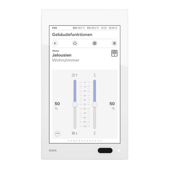
Note Hold finger on start position Before moving the finger, briefly rest it (approx. 1 s) on the start position of the scale to allow the Gira G1 to carry out the position correction. Gira G1... - Page 37 Operating the Gira G1 (KNX) Blinds or shutters can be controlled using the slide control in the detail view. To Blind/shutters move blinds or shutters up or down or adjust the slats, slide the controller to the Operation using slide desired position.
-
Page 38: Scene Auxiliary Unit
"TV" scene, for example, and to activate it with a function of the Gira G1. If this scene is activated, the blinds move to a certain position, the lighting is dimmed to a defined value, the screen is lowered and the projector switched on. -
Page 39: Room Temperature Presence Button And Mode
Operating the Gira G1 (KNX) Room temperature presence button and mode The presence button can be used to activate the comfort temperature from night Presence button mode or frost/heat protection. This function can be used to raise the room tem-... -
Page 40: Timer
"Heating" or "Cooling" operating mode. When the Gira G1 is used as a room temperature controller, the setpoint temper- Changing the set- atures of the "Comfort", "Standby" and "Night" operating modes can be point temperatures changed in the [Operating mode] view. -
Page 41: Creating A Switching Time
Operating the Gira G1 (KNX) 4.10.1 Creating a switching time • 1 Tap the [Timer] button in the detail view of the relevant function. F The [Timer overview] page opens. Figure 32 Overview Timer 2 Tap the [+] button. F The [Timer] page opens. -
Page 42: Deleting A Switching Time
Operating the Gira G1 (KNX) 4.10.2 Deleting a switching time 1 Open the [Timer overview] page. 2 Tap the [Edit] button. 3 Mark the switching time to be deleted. You can also mark and delete several switching times here. F A red tick appears in front of the switching time. The red [Delete] button is shown. -
Page 43: Function Folder
Operating the Gira G1 (KNX) 4.11 Function folder Functions are stored in function folders. Individual functions can be bundled in a function folder, e.g. all the light func- tions, to provide a better overview. Function folders also offer the possibility of mapping a simple building structure, e.g. -
Page 44: Configuring The Gira X1 Client
Figure 36 View [Settings] 1 If the Gira G1 is connected to the network via LAN and DHCP, you can pro- ceed directly to step 2. If the Gira G1 is connected to the network via WLAN and/or without DHCP, you must first connect to the network before you can connect to the Gira X1. -
Page 45: Gira X1 Client Settings
Gira X1 Client settings Basic settings of the Gira G1 can be made in the [Settings] view. 1 Open the [Settings] view by tapping the gear symbol in the navigation bar. F This takes you to the [Settings] view with the following subcategories:... - Page 46 Figure 38 Menu structure Select direct function [see 6.1.1] [Settings] System [see 6.1.2] Connection to the Gira device [see 6.1.2.1] Change password [see 6.1.2.2] Date/time [see 6.1.2.3] Configure WLAN* [see 6.1.2.4] Configure network [see 6.1.2.5] Network connection type [see 6.1.2.6] Set proximity sensor [see 6.1.2.7]...
-
Page 47: System Menu
It is recommended to choose one of the main functions of the room in which the Gira G1 is positioned here, e.g switching the ceiling light. 1 Tap the [Select direct function] button in the system menu. -
Page 48: System
F The [System] page opens. Figure 40 System settings The following menu items are available: Connection to Gira X1 [see 6.1.2.1] Change password [see 6.1.2.2] Date/time [see 6.1.2.3] Configure WLAN [see 6.1.2.4] (only displayed if "WLAN" was selected as the network connection type) Configure network [see 6.1.2.5]... -
Page 49: Connection To Gira X1
Connection to Gira X1 Figure 41 Connection to Gira X1 To connect the Gira G1 to the Gira X1, proceed as follows: 1 Enter the IP address of the Gira X1. 2 Enter the user name and password. 3 Confirm your entries with OK. -
Page 50: Date/Time
Gira X1 Client settings 6.1.2.3 Date/time Here you can set the time and date format in the status bar. Figure 43 Time/date 1 Time: Select 12-hour or 24-hour format. 2 Date: Set the desired date format and accept by tapping [OK]. -
Page 51: Configure Wlan
WLAN network. All WLAN networks in the vicinity of the Gira G1 are displayed under "Available Available WLAN net- WLAN networks". If you wish to connect the Gira G1 to one of the listed WLAN works networks, proceed as follows: 1 Tap the WLAN network with which you wish to connect the Gira G1. -
Page 52: Configure Network
When configuring the network access of the Gira G1, you can choose between DHCP automatic (DHCP) and manual configuration of the network. DHCP is selected in the factory settings of the Gira G1. In this case, the network parameters are automatically specified by the router. Figure 45... -
Page 53: Network Connection Type
Gira X1 Client settings 6.1.2.6 Network connection type Specify here if you want to connect the Gira G1 to the network via LAN or WLAN. Figure 46 Network connection type 1 Select the desired connection type (LAN or WLAN) and confirm with [OK]. -
Page 54: Pin Protection
3 Enter a PIN in the upper box and repeat it in the second box. 4 Confirm the entry with [OK]. F The system menu of the Gira G1 can now only be opened after the PIN is en- tered. -
Page 55: View Configuration
Gira X1 Client settings 6.1.4 View configuration In the view configuration, you define the functions displayed and the order of the functions for the action area. 1 Tap the [View configuration] button. F The [View configuration] page opens. Figure 49... -
Page 56: Define Favourites
8 Close and save your settings: Tap [OK]. F A message informs you that changes have been made. 9 Confirm this by tapping [OK]. F The application on the Gira G1 restarts. The defined favourites then appear in the action area. Gira G1... -
Page 57: Sort Functions
F A message informs you that changes have been made. 7 Confirm this by tapping [OK]. F The application on the Gira G1 restarts. The favourites then appear in the ac- tion area in the order defined by you. 6.1.4.4... -
Page 58: Information
Here you will see the currently installed version of the Gira Smart Home app installed on the Gira G1. Available versions If an update is available for the Gira Smart Home app, it will be displayed here. To install the app update, simply tap the new version. Gira G1... -
Page 59: Operating The Gira X1 Client
[3] [Automatic door opener] appears when automatic door opening has been ac- tivated. [4] The warning symbol in the status bar shows that the Gira G1 is no longer functioning. If you tap the warning symbol, the relevant error message is displayed. -
Page 60: Direct Function
In this way, the Gira G1 becomes a simple switch with which the ceiling lamp can be switched on and off, for example. The main function is superimposed over the screen that is currently active and automatically disappears again after a certain period of time. -
Page 61: Detail View
Note Hold finger on start position Before moving the finger, briefly rest it (approx. 1 s) on the start position of the scale to allow the Gira G1 to carry out the position correction. Gira G1... - Page 62 Operating the Gira X1 Client Blinds or shutters can be controlled using the slide control in the detail view. To Blind/shutters move blinds or shutters up or down or adjust the slats, slide the controller to the Operation using slide desired position.
-
Page 63: Scene Auxiliary Unit
"TV" scene, for example, and to activate it with a function of the Gira G1. If this scene is activated, the blinds move to a certain position, the lighting is dimmed to a defined value, the screen is lowered and the projector switched on. -
Page 64: Room Temperature Presence Button And Mode
Operating the Gira X1 Client Room temperature presence button and mode The presence button can be used to activate the comfort temperature from night Presence button mode or frost/heat protection. This function can be used to raise the room tem-... -
Page 65: Timer
Operating the Gira X1 Client Night Activate night mode during night hours or during a long absence. This adjusts the room temperature to cooler temperatures in heating systems (e.g. in bed- rooms). In this case, cooling systems can be set to higher temperature values when air conditioning is not necessary (e.g. -
Page 66: Creating A Switching Time
Operating the Gira X1 Client 7.8.1 Creating a switching time • 1 Tap the [Timer] button in the detail view of the relevant function. F The [Timer overview] page opens. Figure 61 Overview Timer 2 Tap the [+] button. F The [Timer] page opens. -
Page 67: Deleting A Switching Time
Operating the Gira X1 Client 7.8.2 Deleting a switching time 1 Open the [Timer overview] page. 2 Tap the [Edit] button. 3 Mark the switching time to be deleted. You can also mark and delete several switching times here. F A red tick appears in front of the switching time. The red [Delete] button is shown. -
Page 68: Function Folder
Operating the Gira X1 Client Function folder Functions are stored in function folders. Individual functions can be bundled in a function folder, e.g. all the light func- tions, to provide a better overview. Function folders also offer the possibility of mapping a simple building structure, e.g. -
Page 69: Recording A Simulation
Operating the Gira X1 Client 7.10.1 Recording a simulation Before you can use the simulation function, the building functions to be played during your absence have to be recorded for 7 days. For this, please proceed as follows: 1 Open the [Occupancy simulation] page. -
Page 70: Sonos Audio Function
Operating the Gira X1 Client 7.11 Sonos audio function You can control the Sonos sound systems via the Gira Smart Home app using the "Sonos audio" function. The following functions are available: Play/pause track, change volume, mute, switch between tracks (previous and next track), display track, artist, album and playlist and change playlists (previous and next playlist). -
Page 71: Configuration Of The Playlists
An option is available that lets you adapt the sequence or the number of Sonos playlists for the Gira Smart Home app. This is done on the diagnostic page of the Gira X1: 1 Open the Gira X1's diagnostic page: To do so, open Windows Explorer on your PC and open the “Network”... -
Page 72: Behaviour Of The Playlists After Using The Save Function
KNX pushbutton sensor is not changed accidentally by the addition of a playlist in the Sonos app. If a playlist from the Sonos app should be copied into the saved list of the Gira Smart Home app, then this needs to be carried out on the diagnostic page of the Gira X1. -
Page 73: Configuring The Alarm Connect Security System
Figure 67 View [Settings] 1 If the Gira G1 is connected to the network via LAN and DHCP, you can pro- ceed directly to step 2. If the Gira G1 is connected to the network via WLAN and/or without DHCP, you must first connect to the network before you can connect to the security system. -
Page 74: Alarm Connect Security System Settings
Gira G1. The following examples always show the complete version. If, for example, you do not want to operate a Gira door communication system, the respective con- figuration options are not displayed. Gira G1... - Page 75 Figure 69 Menu structure Select direct function [see 9.1.1] [Settings] System [see 9.1.2] Connection to the Gira device [see 9.1.2.1] Change password [see 9.1.2.2] Date/time [see 9.1.2.3] Configure WLAN* [see 9.1.2.4] Configure network [see 9.1.2.5] Network connection type [see 9.1.2.6] Set proximity sensor [see 9.1.2.7]...
-
Page 76: System Menu
It is recommended to choose one of the main functions of the room in which the Gira G1 is positioned here, e.g switching the ceiling light. 1 Tap the [Select direct function] button in the system menu. -
Page 77: System
F The [System] page opens. Figure 71 System settings The following menu items are available: Connection to the Gira device [see 9.1.2.1] Change password [see 9.1.2.2] Date/time [see 9.1.2.3] Configure WLAN [see 9.1.2.4] (only displayed if "WLAN" was selected as the network connection type) Configure network [see 9.1.2.5]... -
Page 78: Connection To The Gira Device
Figure 72 Connection to the Gira device To connect the Gira G1 to the security system, proceed as follows: 1 Enter the IP address of the alarm control unit Connect. 2 Enter the user name and password. 3 Confirm your entries with OK. -
Page 79: Date/Time
Here you can set the time and date format in the status bar. Figure 74 Time/date 1 Time: Select 12-hour or 24-hour format. 2 Date: Set the desired date format and accept by tapping [OK]. F The selected formats are directly displayed in the status bar. Gira G1... -
Page 80: Configure Wlan
WLAN network. All WLAN networks in the vicinity of the Gira G1 are displayed under "Available Available WLAN net- WLAN networks". If you wish to connect the Gira G1 to one of the listed WLAN works networks, proceed as follows: 1 Tap the WLAN network with which you wish to connect the Gira G1. -
Page 81: Configure Network
When configuring the network access of the Gira G1, you can choose between DHCP automatic (DHCP) and manual configuration of the network. DHCP is selected in the factory settings of the Gira G1. In this case, the network parameters are automatically specified by the router. Figure 76... -
Page 82: Network Connection Type
Alarm Connect security system settings 9.1.2.6 Network connection type Specify here if you want to connect the Gira G1 to the network via LAN or WLAN. Figure 77 Network connection type 1 Select the desired connection type (LAN or WLAN) and confirm with [OK]. -
Page 83: Pin Protection
3 Enter a PIN in the upper box and repeat it in the second box. 4 Confirm the entry with [OK]. F The system menu of the Gira G1 can now only be opened after the PIN is en- tered. -
Page 84: View Configuration
Here you can define whether the Home view is displayed in tile or detail view when the Home button is tapped. Figure 81 Select Home 1 Select the desired view for the Home view. 2 Tap the [OK] button. Gira G1... -
Page 85: Define Favourites
8 Close and save your settings: Tap [OK]. F A message informs you that changes have been made. 9 Confirm this by tapping [OK]. F The application on the Gira G1 restarts. The defined favourites then appear in the action area. Gira G1... -
Page 86: Sort Functions
F A message informs you that changes have been made. 7 Confirm this by tapping [OK]. F The application on the Gira G1 restarts. The favourites then appear in the ac- tion area in the order defined by you. 9.1.4.4... -
Page 87: Operating The Alarm Connect Security System
[2] [Automatic door opener] appears when automatic door opening has been ac- tivated. [3] The warning symbol in the status bar shows that the Gira G1 is no longer functioning. If you tap the warning symbol, the relevant error message is displayed. -
Page 88: Externally Activating A Security Area
[2] External activation not possible 10.4 Externally activating a security area To externally activate a security area via the Gira G1, proceed as follows: 1 Tap the operation unit tile of the security area that you would like to externally activate. -
Page 89: Internally Activating A Security Area
Operating the Alarm Connect security system 10.5 Internally activating a security area To internally activate a security area via the Gira G1, proceed as follows: 1 Tap the operation unit tile of the security area that you would like to internally activate. -
Page 90: Viewing And Acknowledging Alarms And Messages
F If the right PIN has been entered, the message will be removed from the list. Figure 92 Alarms and messages Building functions Operating unit Apartment Kleve Messages confirm cancel PIN confirmation required for the following event: Sabotage alarm to alarm control unit Gira G1... -
Page 91: Configuring The Gira Homeserver Client/Enet Client
Initial commissioning Once you have selected the “Gira HomeServer/eNet Server” option in the basic configuration of the Gira G1 and tapped [Start], the Gira G1 launches the initial commissioning configuration, then displays a start page in which you can imple- ment the settings. -
Page 92: Navigation Bar
Configuring the door communication system [see 15]. Configuring the weather forecast [see 17]. If you activate the “Select as main application” setting for an app, the Gira G1 Select as main appli- displays this app when you reactivate it from idle state. You can only use this cation option for one app. -
Page 93: Settings
Gira G1. You can also view technical information and license texts here. 11.4 Wireless & Networks You can connect the Gira G1 to the network either per LAN or WLAN. Warning Failure of Gira G1 The network connection can fail when network settings are changed. This can lead to functional disturbances of the Gira G1. -
Page 94: Configure Lan Network
Configure LAN network Note Deactivate WLAN The WLAN function must be switched off if you wish to connect the Gira G1 to the network via LAN. When configuring the network access of the Gira G1, you can choose between DHCP automatic (DHCP) and manual configuration of the network. -
Page 95: Configure Wlan
11.4.2 Configure WLAN Note No WLAN with PoE connection module If the Gira G1 is run with a PoE connection module, operation via a WLAN con- nection is not possible. Figure 97 Configure WLAN If you have activated the WLAN function using the slider switch, all WLAN net- Available WLAN net- works located in the Gira G1 environment are displayed in the "WLAN"... -
Page 96: Establish Wlan Connection Via Wps
3 Tap the entry [WPS Push Button] in the menu which opens. F The connection to the WLAN network is established automatically. Connect the Gira G1 to the WLAN as follows via the "WPS with PIN entry" func- WPS with... -
Page 97: Advanced Wlan Settings
Configuring the Gira HomeServer Client/eNet Client 11.4.3 Advanced WLAN settings To open the menu of advanced WLAN settings, please tap the menu symbol in the top right corner of the Gira G1 within the WLAN settings. Figure 98 Advanced WLAN settings... -
Page 98: Device
Device 11.5.1 Set proximity sensor Here you can set the distance at which the Gira G1 is activated from sleep mode when a hand approaches. 1 Tap [Proximity sensor], then [Set proximity sensor]. F The [Set proximity sensor] page opens. -
Page 99: System
3 Enter a PIN in the upper box and repeat it in the second box. 4 Confirm the entry with [OK]. F The settings menu of the Gira G1 can now only be opened after the PIN is en- tered. -
Page 100: Information
Configuring the door communication system [see 15]. Configuring the weather forecast [see 17]. If you activate the “Select as main application” setting for an app, the Gira G1 Select as main appli- displays this app when you reactivate it from idle state. You can only use this cation option for one app. -
Page 101: Configuring The Gira Homeserver App
The following prerequisites must be fulfilled for commissioning to be successful: The Gira HomeServer must be configured to be functional. A user is configured for the Gira G1 in the QuadConfig of the HomeServer ex- pert. Please select the design "0" in the QuadConfig for the Gira G1. - Page 102 XYZ123.giradns.com from the Gira device portal, you can also enter this in the address field. Access data: Enter here the user name and password for the connection to the Gira Home- Server. 3 After entering all the data, tap [Save].
-
Page 103: Operating The Gira Homeserver App
Operating the Gira HomeServer app Start the Gira HomeServer app by tapping the icon with the Gira symbol on the start screen. The Gira HomeServer app is divided into three areas, which can be opened by tapping on the corresponding tab: Menu [see 13.1] Favourites [see 13.2]... -
Page 104: Favourites
Operating the Gira HomeServer app 13.2 Favourites The favourites make frequently used functions even more easily accessible in a view. Figure 103 Favourites view You can easily create your own list of favourites. Before adding functions to the favourites list, or editing the existing favourites list, first activate favourites configuration mode [see 13.3.3]. -
Page 105: System
Operating the Gira HomeServer app 13.3 System Settings for the HomeServer app can be made in the "System" view. Please note that several settings on the Gira G1 have no function. Figure 104 System The following settings are available: Profiles [see 13.3.1] Profile settings [see 13.3.2]... -
Page 106: Profiles
HomeServer expert. Addresses: The IP addresses or URLs of the HomeServer are entered here. If you have received an address in the form of XYZ123.giradns.com from the Gira device portal, you can also enter this in the address field. Access data: Enter here the user name and password for the connection to the HomeServ- 3 After entering all the data, tap [Save]. -
Page 107: Profile Settings
Operating the Gira HomeServer app 13.3.2 Profile settings You can determine here the behaviour of the HomeServer app when starting. Figure 106 Profile settings You can choose here between the following functions: Select profile If you select this option, the HomeServer app displays the "Profiles" view af- ter starting, and you can select the profile that should be displayed. -
Page 108: Configure Favourites
Operating the Gira HomeServer app 13.3.3 Configure favourites You can store the functions most frequently used in the favourites list. Using the function "Configure favourites", you can edit or transfer functions from the menu to the favourites list. Figure 107... -
Page 109: Configuring The Enet Client
The following prerequisites must be fulfilled for commissioning to be successful: The Gira eNet server must be configured to be functional. The Gira G1 and the Gira eNet server are within the same network. The “HomeServer / eNetClient” option has been selected in the Gira G1’s ba- sic configuration. -
Page 110: Configuring Door Communication
When combined with the Gira DCS-IP gateway and a video door station, the Gira G1 can be used as a home station. The camera image of the door station auto- matically appears in the display of the Gira G1 when the doorbell rings. Commu- nication can be initiated, the door can be opened or the light can be switched on at the touch of a finger. -
Page 111: Connecting To The Dcs-Ip Gateway
DCS-IP gateway (see documentation for DCS-IP gateway at www.download.gira.de H). For set-up on the Gira G1, the access data for the DCS-IP gateway must be en- tered. Open the system menu and enter the access data for the Gira door com- munication system. -
Page 112: Access Data
The access data for the door communication system is entered in this view. For this, a DCS communicator for the Gira G1 must first be set up using the TCS-IP gateway assistant. The user name and password data specified there are en- tered into the respective fields. -
Page 113: Operating Door Communication
Accepts an incoming call. More details [see 16.2]. Note Freely configurable buttons During configuration, various functions can be assigned to the two central but- tons of the user interface. ("Switch lights" and "Activate automatic mode" in this example). Gira G1... -
Page 114: Operating Calls
An active automatic door opener is indicated in the status bar. Execute switching action Triggers a switching action via a DCS switching actuator. Call DCS communicator Triggers a call to a different DCS communicator (e.g. on an additional Gira G1). Call door station Triggers a call to a door station. -
Page 115: Resuming A Call
In case of several cameras, the camera taught-in first will be displayed. You can switch between camera images by swiping horizontally. 2 Tap the [Camera] button again to switch the camera off. F The camera has been switched off. Gira G1... -
Page 116: Door Communication System Menu
Forwarding This function enables you to activate door call forwarding on a mobile phone. Note The forwarding function is only available on a Gira TCS-IP gateway of version 4.0 or higher. 1 Tap the [Forwarding] button. F The [Activate forwarding] page opens. Here you can find a list of the call for- wardings set up and assigned to the Gira G1. -
Page 117: Call Door Station
1 Tap the [Call door station] button. F The [Call door station] page opens. Here you can find a list of the door sta- tions assigned to the Gira G1. 2 Tap the door station you want to call. F The call to the door station is established. -
Page 118: Automatic Door Opener
The access data for the door communication system is entered here. For this, a DCS communicator for the Gira G1 must first be set up using the TCS-IP gateway assistant. The user name and password data specified there are entered into the respective fields. -
Page 119: Voice Volume
Gira G1. Carry out setting the volume with 2 people To check the volume level, one person should be at the Gira G1 and another per- son at the door station. 1 Tap the [Voice volume] button. -
Page 120: Weather Forecast
The weather forecast draws its data from Gira’s online weather service. The Gira G1 must be connected to the internet in order for you to be able to use the weather forecast. The weather forecast function is configured and set on the Gira G1. -
Page 121: Changing The Order Of Weather Stations
F A red tick mark will appear in the check box. The red [Delete] button is shown. 5 Tap the [Delete] button. F The weather station will be deleted. 6 Tap the [OK] button. F Shifting points will be displayed again instead of activation check boxes. Gira G1... -
Page 122: Reading Weather Data
Figure 115 Reading weather data 2 Tap the [i] button for more detailed information on the weather. 3 Swipe horizontally to view the data for the other selected weather stations. Gira G1... -
Page 123: Firmware Update
Adding firmware Firmware updates for the Gira G1 are performed using the Gira Project Assistant. The new firmware must be added to the Gira Project Assistant before it can be loaded onto the Gira G1. You can store different firmware versions for your devices in the Gira Project As- sistant so that you can then load them onto the corresponding devices in the "Action Center"... -
Page 124: Adding Firmware Automatically
4 Click the gear symbol and then "Select firmware" to select the firmware ver- sion. 5 Select the desired firmware version. 6 To load the firmware onto the device, click "Start update". F After installation, the Gira G1 restarts and shows the start screen of the Gira Gira G1... -
Page 125: Appendix
Should the Gira G1 stop reacting, you can restart the Gira G1 using a commer- cially available magnet: 1 Place the magnet in front of the Gira logo of the Gira G1 for approx. 3 s. F The Gira G1 restarts, the configuration is retained. -
Page 126: List Of Available Symbols
Hotel Open door Exercise room Heating Workshop Gas-fired boiler Garage Gas flame Loading ramp Temperature Garden Socket outlet Flower Dining room Tool Kitchen Swimming pool Hall Whirlpool Children's room Sauna Playroom Staircase Baby-care room Poolroom Wine cellar Laundry Gira G1... - Page 127 Adjoining building Presentation Parking deck RGB colour picker Parking place Electric iron Wardrobe Forklift Conference room Lift Helicopter Solar collector Camera House Emergency exit Factory Escape Office building Holiday Weather station Consumption values Barrier Diagrams Shopping cart Bell Gira G1...
- Page 128 Internet Rain Globe Eco mode Memory card Automation Email Receiver User profile On-off switch Information Outdoor area Save Part of building Calculator Switch cabinet Cellar Ground floor Warning Storey High rack Attic Message Room Smoking area Break room Gira G1...
- Page 129 Tested, selected Caps Lock key Change colour LED signal light Note Important information I/O module Main menu I/O module input Context menu I/O module output Change sequence Motion detector Project scope Motion detector with Rename camera Power supply Delete Gira G1...
- Page 130 PID controller Draft Random generator Note Separating plate Quick Send-by-change Slow Covering Keypad Timer folder Logic Staircase light Value generator Type converter Counter Sunrise Telegram delayer Press, touch Demultiplexer User Lock-out User group Edge detector Administrator Heating/Cooling Installer Gira G1...
- Page 131 Internally activated Medal Internally and exter- Manual alarm nally activated Alarm Security guard Outgoing call Device in building Externally activated Alarm in building event Internally activated Help video event Externally activated Marked corner alarm Bell Alarm system settings Gira G1...
- Page 132 Changeover switch Arrow / redo NC contact Arrow / undo NO contact Scene set 12V output Information, mes- 0V output sages Subsystems Gira G1 Urgent technical Percent alarm Roof window Green tick Server Question Bluetooth Download Selection / jump to...
-
Page 133: Gira G1 Design
Appendix 19.4 Gira G1 design Figure 118 Front view [1] Touch screen [2] LED [3] Proximity sensor [4] Microphone Figure 119 Side view [1] Unlocking opening [2] Sound channel Gira G1... -
Page 134: Gira G1 Dimensions
Appendix 19.5 Gira G1 dimensions Figure 120 97 mm Dimensions 48,5 mm 48,5 mm Gira G1 Gira G1... -
Page 135: Poe Connection Module Terminal Assignment
The warranty is provided in accordance with statutory requirements via the re- tailer. Please submit or send faulty devices postage paid and with an error description to your sales representative (retailer / installation company / electrical contrac- tor). They will forward the devices to the Gira Service Centre. Gira G1...
Need help?
Do you have a question about the G1 and is the answer not in the manual?
Questions and answers