Gira G1 Installation And Operating Instructions For The Installer
Hide thumbs
Also See for G1:
- Installation manual (36 pages) ,
- Assembly and operating instructions manual (135 pages) ,
- Installation instructions (2 pages)

Related Manuals for Gira G1


Summary of Contents for Gira G1
- Page 1 Gira G1 230 V 2067 05 / 2067 12 PoE 2069 05 / 2069 12 24 V 2077 05 / 2077 12 [EN] Installation and operating instructions for the installer Important: Before use, please read carefully. Please keep for subsequent reading.
-
Page 2: Table Of Contents
Project planning KNX devices ............P. 22 KNX functions ................P. 23 Topology PoE ................P. 24 5.3.1 Gira G1 in main line ..............P. 24 5.3.2 Gira G1 in area line ............... P. 26 Topology WLAN ................P. 28 5.4.1... - Page 3 Activating and deactivating all switching times of a function ..P. 46 6.12 Function folder ................P. 47 Setting up door communication ..........P. 48 Connecting Gira G1 with the door communication system ..P. 48 Establishing connection to the TKS-IP gateway ......P. 49 7.2.1 Access data .................. P. 50 Operating door communication ...........
- Page 4 Manual device restart using magnet ..........P. 60 10.3 List of symbols that can be selected ..........P. 61 10.4 Dimensions of Gira G1 ..............P. 64 10.5 Terminal assignment of PoE connection module ......P. 65 Warranty ..................P. 65...
-
Page 5: Structure Of The Gira G1
Structure of the Gira G1 Figure 1 Front view [1] Touchscreen [2] LED [3] Proximity sensor [4] Microphone Figure 2 Side view [1] Unlocking opening [2] Sound duct Gira G1 installation and operating instructions 0.258 21/2015... -
Page 6: User Interface
User interface Structure of the user interface Figure 3 User interface The user interface of the Gira G1 is divided into 5 areas: [1] Status bar [see 2.2] [2] Information bar (shows which application is open) [3] Navigation bar [see 2.3] [4] Action area [see 2.4]... -
Page 7: Status Bar
[2] The display [automatic door opener] is shown if the automatic door opener is activated. [3] The warning symbol in the status bar shows that the Gira G1 is no longer functioning. If you touch the warning symbol with your finger, the corresponding error message is displayed. -
Page 8: Action Area
The action area is the central working area by means of which you can operate and set the Gira G1. Here, you can operate all applications such as the weather forecast, the Gira door communication system, the function folder and the KNX functions. -
Page 9: Direct Function
This turns the Gira G1 into a simple switch, for example, that can be used for switching the ceiling light on and off. The main function is shown over the currently active display, and disappears automatically again after a certain length of time. -
Page 10: Setting Up Gira G1
The start-up program starts automatically when the operating voltage is switched on. 2 A start-up wizard is displayed when the Gira G1 is set up for the first time. Follow the instructions on the screen. 3 Define the language setting for the Gira G1. -
Page 11: Settings
The number of menu entries in the [Settings] view depends on the applications that you want to operate on the Gira G1. The examples below always show the full range of features. For example, if you do not want to operate a Gira door communication system, the corresponding setting options are not displayed. - Page 12 Ring tone volume** [see 8.6.7] Weather stations Selecting weather station [see 9.1.1] Information License agreements * Only appears if WLAN is selected as the connection type ** Only appears after successful connection with the TKS-IP gateway Gira G1 installation and operating instructions 0.258 21/2015...
-
Page 13: System Menu
3 Activate the selection box after the function that should be used as the direct function. 4 Touch the [OK] button. The data is saved. The system menu is opened. Gira G1 installation and operating instructions 0.258 21/2015... -
Page 14: System
Figure 12 Time/date 1 Time: Select between 12 and 24-hour format. 2 Date: Set the required date format and confirm with [OK]. The selected formats are displayed directly in the status bar. Gira G1 installation and operating instructions 0.258 21/2015... -
Page 15: Configuring Wlan
The “Available WLAN networks” area displays all WLAN networks that are in the Available WLAN net- vicinity of the Gira G1. If you want to connect the Gira G1 to one of the listed works WLAN networks, proceed as follows: 1 Touch the WLAN network that you want to connect with the Gira G1. -
Page 16: Configuring Network
When you configure the network access for the Gira G1, you can choose DHCP between automatic (DHCP) and manual configuration of the network. DHCP is selected in the factory settings of the Gira G1. In this case, the network param- eters are automatically specified by the router. Figure 14... -
Page 17: Network Connection Type
Setting proximity sensor 2 Select between the settings of the proximity sensor: Off (the proximity sensor is deactivated, i.e. to switch on the Gira G1 it is nec- essary to touch the surface), Near (sensor responds at a close distance),... -
Page 18: Reliable Knx Communication
KNX communication” is an expansion to the KNXnet/IP protocol to minimize data losses in communication via potentially unreliable connections (e.g. WLAN). Please activate this function if the Gira G1 is connected to the network via WLAN. To use the “Reliable KNX communication” function, it is necessary to use suit- able peripheral components in the system (e.g. -
Page 19: Selecting Home
Defining favorites Here, you can select functions that are displayed directly in the action area. The Gira G1 can display a maximum of 25 functions as favorites in the action area. 1 Touch the [Define favorites] button. The [Define favorites] page is opened and shows all available function folders. -
Page 20: Sorting Functions
The [View configuration] page is opened. 7 Finish and save your settings: Touch [OK] to do this. A message appears telling you that changes are being saved and the Gira G1 is restarting. 8 Confirm this information with [OK]. The Gira G1 is restarted. Then, the defined favorites appear in the action area. -
Page 21: Restoring Defaults
A message appears telling you that changes are being saved and the Gira G1 is restarting. 7 Confirm this information with [OK]. The Gira G1 is restarted. Then, the favorites appear in the action area in the sequence you have defined. 4.1.3.4... -
Page 22: Setting Up Knx Building Functions
Setting up KNX building functions Project planning KNX devices The Gira G1 is a product in the KNX system and corresponds to the KNX guide- lines. Detailed technical knowledge is a prerequisite for correct understanding. The Gira G1 can be used as a multifunctional room control unit for an existing or newly installed KNX system. -
Page 23: Knx Functions
The Gira G1 can manage up to 125 functions: 5 function folders or rooms, each with up to 25 functions. The Gira G1 offers weekly timer switches each with 10 switching times for the... -
Page 24: Topology Poe
Setting up KNX building functions Topology PoE The Gira G1 is integrated into either the main or area line of the KNX system via a KNX IP router. At the same time, the Gira G1 can be integrated into either the main or area line. - Page 25 Setting up KNX building functions When the Gira G1 is installed in the main line, project planning in the ETS4 or ETS5 would be like this: ETS4: ETS5: Figure 24 ETS screenshot: Gira G1 in main line Left: ETS4 Right: ETS5 Gira G1 installation and operating instructions 0.258 21/2015...
-
Page 26: Gira G1 In Area Line
5.3.2 Gira G1 in area line The following topology shows how the Gira G1 is operated in the area line. In this case, the KNX IP router is used as an area coupler and the area/line couple as a line coupler. - Page 27 When the Gira G1 is installed in the area line, project planning in the ETS4 or ETS5 would be like this: ETS4: ETS5: Figure 26 ETS screenshot: Gira G1 in area line Left: ETS4 Right: ETS5 Gira G1 installation and operating instructions...
-
Page 28: Topology Wlan
If you establish a tunneling connection (KNXnet / IP), the KNX telegrams will be transferred reliably by the Gira KNX IP router (article no. 2167 00, from firmware version 3.0 onwards), even in the WLAN. Please activate the “Reliable commu- nication”... -
Page 29: Connecting Start-Up Pc Via Knx Usb Interface
5.4.2 Connecting start-up PC via KNX USB interface You can also take the Gira G1 (WLAN) into operation via a KNX USB interface. All telegrams will be transferred reliably if the “Reliable communication” func- tion is activated on the Gira KNX IP router (article no. 2167 00, from firmware version 3.0 onwards) and on the Gira G1. -
Page 30: Operating Knx Building Functions
6.1.1 Tile view 1 Touch the corresponding button to switch the lighting on or off. Switching The load is switched on or off, and the corresponding status is shown on the tile. Gira G1 installation and operating instructions 0.258 21/2015... -
Page 31: Detailed View
The load is switched on or off, and the corresponding status is shown. 6.2.2 Detailed view 1 Touch the button to switch the lighting on or off. Switching The load is switched on or off, and the corresponding status is shown. Gira G1 installation and operating instructions 0.258 21/2015... -
Page 32: Dimming
If you want to change the brightness value, you first need to switch to the detailed view by touching the tile. Gira G1 installation and operating instructions 0.258 21/2015... -
Page 33: Detailed View
Hold your finger at the start position Hold your finger briefly in position at the start before dragging (approx. 1 s) to allow the Gira G1 to carry out the position correction. A timer switch can be configured for the “dimming” function [see 6.11]. -
Page 34: Blind / Roller Shutter (Step Move)
1 To adjust the slats of the blind, touch the up or down button for less than one Adjusting slats second. The slat position changes in the required direction. A timer switch can be configured for the “blind/roller shutter” function [see 6.11]. Timer switch Gira G1 installation and operating instructions 0.258 21/2015... -
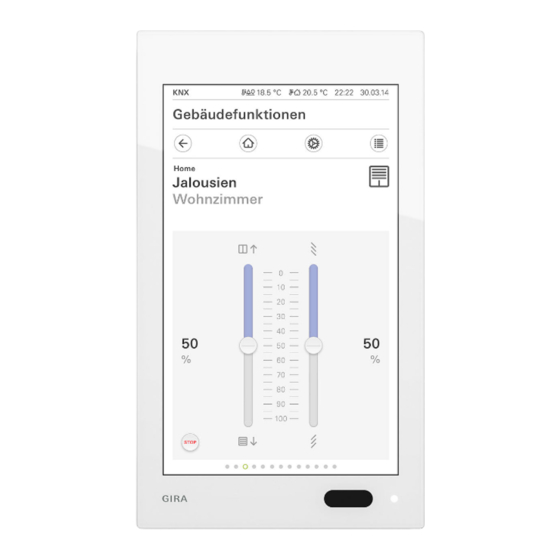
Page 35: Blind Positioning
Adjusting slats Adjusting slats is not possible in the tile view Adjusting slats is not possible in the tile view. To do this, switch to the detailed view by touching the tile. Gira G1 installation and operating instructions 0.258 21/2015... -
Page 36: Detailed View
Stop key or a slat adjustment directly. The activated curtain then stops directly in its cur- rent position. A timer switch can be configured for the “blind” function [see 6.11]. Timer switch Gira G1 installation and operating instructions 0.258 21/2015... -
Page 37: Roller Shutter Positioning
By touching the “STOP” button, you can stop an active movement of the curtain Stop key directly. The activated curtain then stops directly in its current position. A timer switch can be configured for the “roller shutter” function [see 6.11]. Timer switch Gira G1 installation and operating instructions 0.258 21/2015... -
Page 38: Scene Extension Unit
For example, you can create the “TV” scene and call it up with a function of the Gira G1. When this scene is activated, for example, the blinds move to a particular position, the lighting is dimmed to a defined value, the projector screen is lowered and the project is switched on. -
Page 39: Detailed View
A message appears. 4 Touch the [OK] button. The [Scene setting] page is opened. The scene is saved. A timer switch can be configured for the “scene extension unit” function [see Timer switch 6.11]. Gira G1 installation and operating instructions 0.258 21/2015... -
Page 40: Encoder
The value displayed next to the button is sent to the KNX system. 6.8.2 Detailed view 1 Set the required value. Setting and sending 2 Touch OK. value The set value is sent to the KNX system. Gira G1 installation and operating instructions 0.258 21/2015... -
Page 41: Status Display
This display is only used for information about particular statuses. It is not possible to operate or change the values here. Figure 37 Status display Left: Tile view Right: Detailed view Gira G1 installation and operating instructions 0.258 21/2015... -
Page 42: Room Temperature Controller Extension Unit
Operating KNX building functions 6.10 Room temperature controller extension unit The Gira G1 can be used as an extension unit for activating a KNX room tem- perature controller (absolute). Figure 38 Room temperature controller extension unit Left: Tile view Right: Detailed view 6.10.1... - Page 43 Standby Activate standby if a room is not used during the day. This controls the room temperature at a standby value, thereby saving heating or cooling energy. Gira G1 installation and operating instructions 0.258 21/2015...
-
Page 44: Timer Switch
28 switching times. 6.11.1 Creating switching time • 1 Touch the [Timer switch] button in the detailed view of the corresponding function. The [Timer switch overview] page opens. Figure 40 Timer switch overview Gira G1 installation and operating instructions 0.258 21/2015... -
Page 45: Deleting Switching Time
A red tick appears in front of the switching time. The red [Delete] button is displayed. 4 Touch the [Delete] button. The [Timer switch overview] page is opened. The selected switching time is deleted. Gira G1 installation and operating instructions 0.258 21/2015... -
Page 46: Activating And Deactivating All Switching Times Of A Function
All switching times of this function are activated or deactivated. Temporarily deactivating switching times If you want to deactivate individual switching times of a function temporarily, you can simply deactivate all days (set them to gray). Gira G1 installation and operating instructions 0.258 21/2015... -
Page 47: Function Folder
Function folders also offer the opportunity of rep- resenting a simple building structure, e.g. all functions in one room. A function folder can contain a maximum of 25 functions. Figure 43 Function folder Gira G1 installation and operating instructions 0.258 21/2015... -
Page 48: Setting Up Door Communication
Setting up door communication The Gira G1 can be used as a home station in conjunction with the Gira TKS-IP gateway and a video door station. If the doorbell rings, the display of the Gira G1 automatically shows the picture from the door station camera. Communication can be started, the door opened or the light switched on with a touch of a finger. -
Page 49: Establishing Connection To The Tks-Ip Gateway
Establishing connection to the TKS-IP gateway Note Prerequisites For the door communication function to be set up on the Gira G1, there must be a functioning Gira door communication system, a TKS-IP gateway and a com- puter with network access available. -
Page 50: Access Data
For this purpose, it is first necessary to use the wizard of the TKS-IP gateway to set up a TKS communicator for the Gira G1. The data defined there for the user name and password are entered in the corresponding boxes here. -
Page 51: Operating Door Communication
Buttons with programmable functions The two buttons in the middle of the user interface can have different functions assigned to them in the project planning. In this example, “Switch light” and “Switch on automatic function”). Gira G1 installation and operating instructions 0.258 21/2015... -
Page 52: Operating Calls
The [Door call] button lights up red during voice communication. 1 Touch the [Door call] button to terminate the call. The call is terminated. The [Door call] button lights up green. The conversation can be resumed within 30 seconds. Gira G1 installation and operating instructions 0.258 21/2015... -
Page 53: Resuming Call
You can switch between the camera images by means of a horizontal swipe. 2 Touch the [Camera] button again to switch off. The camera is switched off. Gira G1 installation and operating instructions 0.258 21/2015... -
Page 54: Door Communication System Menu
The [Select camera] page is opened. Here, you can find the list of the cameras installed in your system. 2 Touch the camera that you want to select. The door communication view opens and the image from the selected cam- era is displayed. Gira G1 installation and operating instructions 0.258 21/2015... -
Page 55: Ring Tone Melody
TKS-IP gateway to set up a TKS communicator for the Gira G1. The data defined there for the user name and password are entered in the corresponding boxes here. -
Page 56: Speech Volume
The speech volume is a volume used for the conversation with the door station on the Gira G1. Set the volume with 2 people To check the volume, one person should stand in front of the Gira G1 and another person in front of the door station. 1 Touch the [Speech volume] button. -
Page 57: Weather Forecast
The weather forecast obtains data from the online weather service of Gira. The Gira G1 must be connected to the Internet so that the weather forecast can be used. The parameters and settings for the weather forecast are programmed on the Gira G1. -
Page 58: Changing Sequence Of Weather Stations
A red tick is displayed in the checkbox. The red [Delete] button is displayed. 5 Touch the [Delete] button. The weather station is deleted. 6 Touch the [OK] button. Movement points are displayed again instead of the checkboxes. Gira G1 installation and operating instructions 0.258 21/2015... -
Page 59: Reading Out Weather Data
Reading out weather data 2 Touch the [i] button to obtain more precise information about the weather. 3 With a horizontal swipe, you can view the data for the other selected weather stations. Gira G1 installation and operating instructions 0.258 21/2015... -
Page 60: Appendix
If the Gira G1 no longer responds, you can restart the Gira G1 using a conven- tional magnet: 1 Hold the magnet in front of the Gira logo on the Gira G1 for about 3 s. The Gira G1 restarts, the configuration is retained. -
Page 61: List Of Symbols That Can Be Selected
Escape route Child's room Cloakroom Factory Clock Favorites Closed lock Film Cloudy Fitness room Comfort Floor Conference room Floor plan Consumption val- Flower Cooling Forklift truck Cooling/heating Frost protection Corridor Function folder Funnel Gira G1 installation and operating instructions 0.258 21/2015... - Page 62 High rack Multistorey car park Music Nappy-changing Holiday room Hotel Night House No smoking Important Off switch Information Office building Internet Open door Iron Open lock Outbuilding Kitchen Parking space Laundry room Party Gira G1 installation and operating instructions 0.258 21/2015...
- Page 63 Sauna Watering can Save Watering system Scene Settings Weather station Shopping basket Whirlpool Shower Window Smoking area Wine cellar Snooker room Women's WC Socket Workroom Solar collector Stairwell Standby Swimming pool Tablet Gira G1 installation and operating instructions 0.258 21/2015...
-
Page 64: Dimensions Of Gira G1
Appendix 10.4 Dimensions of Gira G1 Figure 51 97 mm Dimensions of 48,5 mm 48,5 mm Gira G1 Gira G1 installation and operating instructions 0.258 21/2015... -
Page 65: Terminal Assignment Of Poe Connection Module
Please bring faulty devices, or send them post-paid, to the outlet where you make your purchase (specialist retailer/installation company/electrical retailer). You should also provide a description of the fault. The devices will be forwarded to the Gira Service Center. Gira G1 installation and operating instructions 0.258 21/2015...
Need help?
Do you have a question about the G1 and is the answer not in the manual?
Questions and answers