
Subscribe to Our Youtube Channel
Related Manuals for MSG Equipment MS002 COM


Summary of Contents for MSG Equipment MS002 COM
- Page 1 2017.05.16 MSG MS002 COM TEST BENCH FOR DIAGNOSTICS OF ALTERNATORS, STARTERS AND VOLTAGE REGULATORS USER MANUAL...
-
Page 2: Table Of Contents
User Manual - Test Bench MSG MS002 COM CONTENTS 1. DESCRIPTION ............................... 2. TECHNICAL CHARACTERISTICS ......................... 3. RECEIPT AND INSPECTION ..........................4. TEST BENCH DESCRIPTION ..........................Mounting Face ............................4.2 Sockets ................................. 4.3 Adjustment Knobs ............................ 4.4 Buttons ................................ 4.5 Display. Data Output .......................... -
Page 3: Description
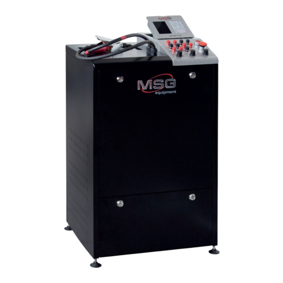
User Manual - Test Bench MSG MS002 COM 1. DESCRIPTION Test Bench MSG MS002 COM is a high power multifunctional test bench. The equipment includes the following diagnostic functions: testing of starters, alternators and voltage regulators without applying any additional measuring devices. -
Page 4: Technical Characteristics
User Manual - Test Bench MSG MS002 COM 2. TECHNICAL CHARACTERISTICS Supply voltage, V 380±10% Supply type Three-phases Battery model (not concluded in the set) Any, up to 60 A*Hr Battery charge 1 Уеs Battery charge 2 Dimensions, mm (length, width, height) -
Page 5: Receipt And Inspection
User Manual - Test Bench MSG MS002 COM - Voltage Measured parameters - Alternating current - Constant current Testing of voltage regulators Voltage, V 12/24 - Stabilizing voltage - Current through rotor winding Tested parameters - COM voltage regulators: protocol,... - Page 6 User Manual - Test Bench MSG MS002 COM Fig. 3. MS002 COM - Control panel Fig. 2. MS002 COM - Mounting face The chain fixer (1) is used to latch the chain (2). The belts (3) and (4) are used to transfer engine torque of the bench on a tested pulley of an alternator.
-
Page 7: Sockets
User Manual - Test Bench MSG MS002 COM 4.2 Sockets • D+: used for testing alternators and voltage regulators with L, D+, I, IL, 61 terminals. LAMP indicator (control lamp simulation on instrument cluster) is lightened next to D+ socket. -
Page 8: Buttons
User Manual - Test Bench MSG MS002 COM 4.4 Buttons • Alternator & starter tester: on/off switch of the testing mode of starters and alternators. The button is lightened in active mode with option to choose voltage and connection to an alternator. -
Page 9: Display. Data Output
User Manual - Test Bench MSG MS002 COM • REGULATION GC: ensures adjustment of output parameters of a voltage regulator, used when a voltage regulator is plugged into GC connection port. Parameters reset after a short pressing. • ELECTRICAL LOAD: the knob for adjusting electrical load on an alternator (simulates vehicle electrical consumers). - Page 10 User Manual - Test Bench MSG MS002 COM Fig. 6. Display data output when Fig. 7. Display data output when testing an alternator with D+ testing an alternator with terminal or a starter P-D terminal Fig. 8. Display data output when Fig.
- Page 11 User Manual - Test Bench MSG MS002 COM Fig. 10. Display data output when Fig. 11. Display data output when testing an alternator with testing an alternator with SIG terminal COM (LIN, BSS) terminal Fig. 12. Display data output when...
- Page 12 User Manual - Test Bench MSG MS002 COM Display Data Output when Testing an Alternator or Starter Display Indicators • VOLTAGE, DC: stabilizing voltage indicator of a voltage regulator. • DFM,%: indicator of load on a voltage regulator. • AMP, DC: indicator of constant current through winding of simulated rotor.
- Page 13 User Manual - Test Bench MSG MS002 COM Fig. 13. MS004COM Fig.14. MS004COM Display data output when testing a voltage Display data output when testing a voltage regulator with L/D+ terminal regulator with P-D terminal Fig. 15. MS004COM Fig. 16. MS004COM...
-
Page 14: Setting Into Operation
User Manual - Test Bench MSG MS002 COM Fig. 17. MS004COM Fig. 18. MS004COM Display data output when testing a voltage Display data output when testing a voltage regulator with SIG terminal regulator with COM terminal 5. SETTING INTO OPERATION 5.1 Connection... -
Page 15: Step-By-Step Instruction
User Manual - Test Bench MSG MS002 COM 6. STEP-BY-STEP INSTRUCTION Before testing the unit, make sure that all bolts are tightened, the test bench is not damaged and has no cracks. 6.1 Alternator Testing • Install the unit must on the mounting face. -
Page 16: Starter Testing
User Manual - Test Bench MSG MS002 COM WARNING! Generation voltage must correspond to the technical data of a tested alternator. WARNING! Discharged batteries may consume up to 50 A of generated current. On finishing testing of an alternator: • Reset the set load by short pressing the adjustment knob ELECTRICAL LOAD. -
Page 17: Test Certificate
7. TEST CERTIFICATE Test Bench MSG MS002 COM for diagnostics of starters, alternators and voltage regulators meets technical requirements of Directive 2014/30/EU - Electromagnetic Compatibility (EMC) EN Directive 2014/35/EU - Low voltage (LVD) Directive 2006/42/EC - Machinery (MD) and is qualified for exploitation. -
Page 18: Appendix 1
User Manual - Test Bench MSG MS002 COM APPENDIX 1 Connection Terminals of Alternators Symbols Functional purpose Connection Battery (+) (Ignition) Input for switch starting Alternator Sense Battery Voltage Sense (Sense) Input for voltage comparison at control point Battery (-) - Page 19 User Manual - Test Bench MSG MS002 COM (Regulated Voltage Control) Similar to SIG, but voltage change ranges RVC(L) from 11.0 V to 15.5 V. Control signal is sent to L terminal (Communication) Voltage regulator input to control engine operation block.
-
Page 20: Appendix 2
User Manual - Test Bench MSG MS002 COM APPENDIX 2 Sockets of Alternators Bosch Denso... - Page 21 User Manual - Test Bench MSG MS002 COM Ford/Lucas Hitachi Magneti Marelli Mitsubishi...
- Page 22 User Manual - Test Bench MSG MS002 COM Delco Remy Valeo...
-
Page 23: Appendix 3
User Manual - Test Bench MSG MS002 COM APPENDIX 3 Connection of Voltage Regulators to the Test Bench... - Page 24 User Manual - Test Bench MSG MS002 COM...
- Page 25 User Manual - Test Bench MSG MS002 COM...
- Page 26 User Manual - Test Bench MSG MS002 COM...
- Page 27 User Manual - Test Bench MSG MS002 COM...
- Page 28 User Manual - Test Bench MSG MS002 COM...
- Page 29 User Manual - Test Bench MSG MS002 COM...
- Page 30 User Manual - Test Bench MSG MS002 COM...
- Page 31 User Manual - Test Bench MSG MS002 COM...
Need help?
Do you have a question about the MS002 COM and is the answer not in the manual?
Questions and answers