Table of Contents
Advertisement
Quick Links
Advertisement
Table of Contents

Related Manuals for Adash VA5 Pro


Summary of Contents for Adash VA5 Pro
- Page 1 USER MANUAL VA5 Pro A4404 SAB Virtual Unit Version 2.69 – July 01, 2019...
-
Page 2: Table Of Contents
ADASH Adash 4500 – VA5Pro Content: VA5 Pro vs. A4404 SAB..................12 VA5 Pro........................... 12 A4404 SAB (Signal Analyzer Box)................... 12 Before Switching On....................13 General Warnings ......................13 General Information....................14 Front View ........................14 Top View ......................... 14 Rear View........................ - Page 3 ADASH Adash 4500 – VA5Pro Units Frequency unit Speed unit Power/Line Frequency Phase range Displayed Spectra in Cascade Align Graphs Graph Grid Cursor Type Record analysis speed Record Analysis Start Touchscreen ........................30 Enable Touchscreen Keyboard......................... 30 Keyboard Backlight Language ........................30 Language Brightness ........................
- Page 4 ADASH Adash 4500 – VA5Pro Sensor Properties for Records AC Sensors ........................37 Sensitivity[mV/unit] Unit Position DC gap channel ISO Machine Group Bearing Type ISO 10816 Machine Groups .................... 38 Bearing Settings ......................38 Bearing type Rotating Race DC Sensors........................38...
- Page 5 ADASH Adash 4500 – VA5Pro Graph Max/Min........................ 52 Graphs Control ........................ 52 Set Menu......................... 54 Save data Notes Clear Data Enter speed / Cancel speed View Trend / View Actual Clear Last Data Meas Menu ........................55 New Basic New Advanced...
- Page 6 ADASH Adash 4500 – VA5Pro Axe Y Axe Z Order Z Detect Type Peaks List Synch Table Bearing Faults Orders Table Statistics Table Primary Cursor View (for center line) View (for frf) View (for 1x amp+phase) View (for phase shift)
- Page 7 ADASH Adash 4500 – VA5Pro Creation of the route tree....................87 Route Measurement......................87 Reference Values......................89 Manual Entry ........................89 Enter Speed ........................90 Cancel Speed........................90 Notes..........................90 Speed in the Route......................92 Speed entered in the instrument...
- Page 8 ADASH Adash 4500 – VA5Pro Balancer Settings ......................105 Basic Settings ....................... 105 Planes Image Look Rotation Inputs Channel Channel A, Channel B Balancing Masses Blades Meas Mode Resolution Units Settings ........................ 107 Amplitude Detect Type Speed Mass Rotor Settings ....................... 107...
- Page 9 ADASH Adash 4500 – VA5Pro The delay of audio output ....................125 Playback Settings......................125 Playback speed Stereo Lubri - the greasing control ................. 127 Two Possible Ways How to Measure ................127 Procedure........................128 Octave Analysis ....................130 Measurement settings ....................130...
- Page 10 Virtual Unit Installation License file Update .......................... 148 Operation ........................148 VA5_DISC........................149 VA5 Virtual unit and VA5 Pro connection............... 149 Copying projects to the instrument Projects and records copy from the instrument Appendix A: Technical Specification ..............150 Inputs ..........................150...
- Page 11 ADASH Adash 4500 – VA5Pro Tacho Channel Static Channels (DC or 4-20mA) Measurement Functions ....................150 Recording:........................151 Balancing: ........................151 General: ........................151 Appendix B : Phase measurement conventions ..........152 Single channel measurement with tacho ............... 152 Dual channel measurement................... 155 Last reminder ........................
-
Page 12: Va5 Pro Vs. A4404 Sab
A4404 SAB is a pocket size vibration analyzer which contains input connectors for sensors. It uses the same DSP board as VA5 Pro but it doesn't contain keyboard and screen. It must be connected with computer via USB. You need to install Virtual Unit application which is the same software used in VA5 Pro. Almost all functions described in this manual work both in the instrument and in the Virtual Unit. -
Page 13: Before Switching On
ADASH Adash 4500 – VA5Pro Before Switching On Ignoring any recommendations mentioned below may cause failure of the device. Operating with a power higher then 24 V can cause an accident. General Warnings Only suitable ICP powered sensors can be connected to the AC signal inputs. -
Page 14: General Information
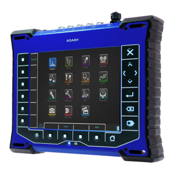
ADASH Adash 4500 – VA5Pro General Information Front View Top View Rear View For further technical and contact information visit www.adash.com or email: info@adash.com... -
Page 15: Battery Charging
ADASH Adash 4500 – VA5Pro Battery Charging Charge the battery only at 0 - 40°C (30 - 100 °F)! The POWER socket for external charger is on the top panel. The battery LED diode lights orange during charging and lights green when fully charged. -
Page 16: Sleep Mode
ADASH Adash 4500 – VA5Pro Sleep Mode Use the POWER button (described in the "Switch on" chapter) to switch the instrument into a sleep mode. The screen is off and power consumption is lower in the sleep mode. Use the same POWER button to wake up again. -
Page 17: Vax_Disc
ADASH Adash 4500 – VA5Pro Until you are not on main screen, the VA5_DISC remains to be connected to the instrument processor and you cannot see it on your PC. The correct connection with PC is announced by the message box. -
Page 18: Input Channels
ADASH Adash 4500 – VA5Pro Input Channels All input sockets are in the top panel. The input sockets IN1, IN2, IN3, IN4 are used for AC and DC signals. The TRIG input socket is used for trigger signals, usually tacho. All sockets have several pins. It enables to connect more signals to one socket (see wire diagrams). -
Page 19: In3 Socket
ADASH Adash 4500 – VA5Pro IN3 Socket 1 – GND 2 – DC2 3 – DC3 4 – DC4 5 – SHLD 6 – DC1 7 – GND 8 – AC3 Pay attention to possibility of connecting all four DC channels to IN3. -
Page 20: Standard Cable Wiring
ADASH Adash 4500 – VA5Pro Standard Cable Wiring The standard cable, which are the part of the VA5 set, have the sensor signal connected to the pin number 8. The second sensor wire is connected to the ground (pin 7). -
Page 21: A4409 - Bnc Box
ADASH Adash 4500 – VA5Pro A4409 - BNC Box This box can simplify the connection of more cables to VA5 inputs. The BNC input connectors are used on the top panel for connection of 4 AC channels and 4 DC channels. On the side panel are two connectors, which enable to connect all 4 AC channels to IN2 input and all 4 DC channels to IN3 input. -
Page 22: Instrument Control
ADASH Adash 4500 – VA5Pro Instrument Control You can control the instrument by buttons around the display or by touch-screen. Buttons on right side have these meanings. Escape / Cancel / Stop / No Up Arrow Left Arrow Right Arrow... -
Page 23: Value Selection
ADASH Adash 4500 – VA5Pro Value Selection Select one item. Then push the right arrow or OK button to display available values. For example for Sensitivity you see this picture: User Defined Values You can select predefined sensitivity or you can enter the user sensitivity (for example 96,8 mV/g). Select the user and push OK. -
Page 24: Item Value Saving
ADASH Adash 4500 – VA5Pro You can also enter a decimal point or minus symbol by several pushes of zero button. Use Backspace button to delete entered characters. Use Ok button to confirm the value or Escape button to leave without any change. -
Page 25: Main Screen
ADASH Adash 4500 – VA5Pro Main Screen After the switching on the main screen appears. Modules The VA5 instrument contains many modules. Each module has an icon on the main screen. Use arrows or double tap the icon to open the module. Each module will be described in separated chapter. -
Page 26: Pc Connection Indication
ADASH Adash 4500 – VA5Pro Battery lifetime 75 – 100 % Battery lifetime 50 – 75 % Battery lifetime 20 – 50 % Battery lifetime 8 – 20 % Battery lifetime 7 % Battery lifetime under 7 %. Instrument is switched off under 3%. -
Page 27: Menu
ADASH Adash 4500 – VA5Pro MENU Press the MENU button. Two parts SETTINGS and RUN appears. All MENU items will be explained. The underlined values are the default values (factory settings). For further technical and contact information visit www.adash.com or email: info@adash.com... -
Page 28: Menu / Settings
ADASH Adash 4500 – VA5Pro MENU / SETTINGS Global Settings Display Route Values on, off When you want to go faster during the route and you do not want to look at measurement results after each point, then set it off. -
Page 29: Frequency Unit
ADASH Adash 4500 – VA5Pro Units available in measurement setup. Frequency unit Hz, RPM, CPS, CPM Speed unit Hz, RPM, CPS, CPM Power/Line Frequency It is used for Elect value in Synch table, which is displayed for spectra Phase range... -
Page 30: Touchscreen
ADASH Adash 4500 – VA5Pro These options are used when the record is selected for analysis. It would be better to use example for explanation. For example we use record which length is 60 sec. We define time signal measurement which length is 8 sec. It means when we push Start button, the reading takes 8 sec and position of cursor moves of 8 sec in record. -
Page 31: Save Settings To "Just Opened Profile Name
ADASH Adash 4500 – VA5Pro Save settings to "just opened profile name" Save the parameters to the currently opened profile (updates the profile). Note! You have to create and open a profile otherwise this item is not visible. Save settings as new profile Save the parameters to the new profile (after name entry). -
Page 32: Date/Time
ADASH Adash 4500 – VA5Pro If you want to create your own note, then push Edit text button. Enter your note manually. Each line in text is one note. Press Enter button to add new line. Press Escape button to skip back to the Factory notes list. -
Page 33: Signal Source
ADASH Adash 4500 – VA5Pro Signal Source The measurement can be taken from LIVE channels ( AC 1-4 or DC 1-4 ) or from RECORD (see Recorder chapter for understanding). All records saved in the memory are displayed for selection. Select required item and press OK button. -
Page 34: Use Ampl Tacho
ADASH Adash 4500 – VA5Pro manual sequential Similar to manual, but every measurement for averaging must be start separately. For example when AVG=10, then the START button must be used 10 times. amplitude The taking of measured data begins when the signal level exceed the Ampl Trig Level, which is set by user also in this menu. -
Page 35: Runup
ADASH Adash 4500 – VA5Pro Usually the taking of measurement (for example time signal) begins exactly from the trigger moment. But in some applications you are interested also to know the signal before trigger. The required time should be define in seconds, but in signal Analyzers is usually defined as percent part of the total signal length. -
Page 36: Sensor Properties For Records
ADASH Adash 4500 – VA5Pro Axe X lin, log Axe Y lin, log, dB Peaks list on, off Graph Lines continuous, discrete Sensors When you connect the sensors to the instrument, you have to tell what kind of sensors you use. Select the Sensors item. -
Page 37: Ac Sensors
ADASH Adash 4500 – VA5Pro Tacho setting of tacho channel properties Settling Prolongation if you need longer time for sensor settling, use this item AC Sensors AC (alternate current) sensors are used for signals, for example vibrations. on, off Select of required setting accordingly the sensor type... -
Page 38: Iso 10816 Machine Groups
ADASH Adash 4500 – VA5Pro ISO 10816 Machine Groups You can set the appropriate machine group according the ISO 10816 for each channel separately or for all channels together. ISO 10816 Classification of machinery. These parameters are used for limit values according to machine type, nominal power or shaft height. -
Page 39: Position
The correct reference value has to be set for speed measurement. For example when the standard tacho level is 0.5V and the pulses rich the 1.5V, then the value 1V should be correct. The negative pulses are not allowed, you need to use Adash converter for them. Pulses per rotation This value has to be set for correct speed evaluation, when more pulses are generated during one rotation. -
Page 40: Menu / Run
ADASH Adash 4500 – VA5Pro MENU / RUN Camera Runs the Camera module. This is next option how to run it. The basic option is to run it from main screen. IR Camera Runs the IR Camera module. Gallery Opens the Gallery module. This is next option how to open it. The basic option is to open it from main screen. -
Page 41: Power Off
ADASH Adash 4500 – VA5Pro Power Off Switch off the instrument. For further technical and contact information visit www.adash.com or email: info@adash.com... -
Page 42: Speed Detection
ADASH Adash 4500 – VA5Pro Speed detection You need to know the speed of the measured machine in some cases. Usually the route readings has set the Detected speed from DDS. We will describe here how the speed detection works. -
Page 43: Analyzer
ADASH Adash 4500 – VA5Pro Analyzer The Analyzer module is the basic module for signal analysis. If you have not prepared the Route measurement, then you use the Analyzer for analysis. All required parameters must be set by hand or you can use the saved measurement parameters from memory. -
Page 44: Project List
ADASH Adash 4500 – VA5Pro Project List The first Analyzer screen contains the list of Projects saved in the memory or the empty list, when no Projects were saved. The time and date of last saving of selected project is displayed in top right corner. Each item in project list has a note on right side, S (means Set), L1 or L2. -
Page 45: New Project - L1/Set Creation
ADASH Adash 4500 – VA5Pro Enter the name of new set. Then press OK. Your new item appears in the displayed Project list (alphabetical order). The S letter after the name is the Set type indication. Date and time of project last modification (here creation) is displayed in status bar right corner. -
Page 46: Copy
ADASH Adash 4500 – VA5Pro The L2 letter after the name is the Level 2 type indication. Open the Project by OK. The empty list of L1 items appears. Press L1 button and select New. Enter the name of new Level 1 item. -
Page 47: Measurement Definition In The Set
ADASH Adash 4500 – VA5Pro The Set screen contains graphs of set's measurements (now empty). The status bar contains several texts. The set's name (Meas_Point_A) takes place in the top left corner. The Actual indicator informs you are working with actual data. The Trend/History alternates the Actual if you are watching saved data. - Page 48 ADASH Adash 4500 – VA5Pro The Type parameter displays current trigger settings as a note under the value. If you need to create same measurement on all channels set the All channels to yes. The Band fmax parameter determines measurement's required sampling frequency. Therefore the fs note is displayed under the Band fmax value.
- Page 49 ADASH Adash 4500 – VA5Pro Create the second measurement. Use the Meas / New Advanced item again. Change the Unit to g, the Band fmin to 500 Hz , the Band fmax to 25600 Hz and the Samples to 65536. Confirm the dialog and the second graph will be ready.
- Page 50 ADASH Adash 4500 – VA5Pro The Set screen contains five graphs of just defined measurements. The graphs don't contain data yet. The Graph 3 / 5 text in the status bar top right corner says that the third graph is selected (you see the red frame) and there are five graphs on the screen.
- Page 51 ADASH Adash 4500 – VA5Pro When the measurements definition is made everything is ready to make the real measurement. Push the Start button. The Device Initialization count down appears in the bottom right corner before the measurement begins. The Measuring indication is in the bottom right corner of the status bar. The RT note means Real Time (see the Input Buffering chapter).
-
Page 52: Input Buffering
ADASH Adash 4500 – VA5Pro When graph contains data the averages and speed notification appear in the graph's top right corner. See the graph 4. The 3/4 means the 3 of 4 averages has been taken and 17.7Hz is the speed on the beginning of the reading. - Page 53 ADASH Adash 4500 – VA5Pro If you tap the selected graph, the cursor moves to the place you tapped (more precisely it will move to the nearest place on signal). Another control functions are available under the side buttons. Press the Zoom button. The buttons mode will change.
-
Page 54: Set Menu
ADASH Adash 4500 – VA5Pro Next available functions of the Control mode are Trend, Delta X, Zoom Z and Move Z. These functions are hidden now and will be shown in certain situations. The Backspace button restores side buttons again. -
Page 55: View Trend / View Actual
ADASH Adash 4500 – VA5Pro View Trend / View Actual Loads saved data of the set. The screen looks like this while looking the saved data. Notice the overall values are displayed as trends. The status bar contains Trend/History notification with the data and time of the beginning of the history. -
Page 56: New Advanced
ADASH Adash 4500 – VA5Pro New Advanced Creates new advanced measurement, where all parameters are available. You can edit type and parameters of the measurement as you need. Then press the Ok button and new measurement's graph will appear on the Set screen. -
Page 57: Export To Csv
ADASH Adash 4500 – VA5Pro Export to csv Exports data of selected measurement to the csv file format. The file is saved to csv folder on the VA5_DISC. The measurement data are saved in individual lines. Each line contains values depending of type of measurement. -
Page 58: Result Type
ADASH Adash 4500 – VA5Pro it is average value of all samples (total sum of absolute values divided by number of samples) Crest it is equal True 0-P/ RMS Kurtosis standard statistical formula for Kurtosis Result Type H1, H2, H3, PAS... -
Page 59: Input Channel
ADASH Adash 4500 – VA5Pro Input channel Required only for response functions Output channel Required only for response functions FFT Window Rectangular, Hanning, Transient, Exponential The standard offer of FFT windows functions. When you select the Transient or the Exponential window you need to define it's Shift and Length, both in miliseconds. -
Page 60: Zoom Spectrum
ADASH Adash 4500 – VA5Pro Now when the window is well set change the view back to the spectrum and take your final reading. In case of the frequency response function you setup two FFT windows for input and output signal. Then a Shift2, Length2 and Shift12 functions are available moreover. -
Page 61: Samples
ADASH Adash 4500 – VA5Pro Samples value Number of samples ( Speed control = off). The signal time length is displayed under this item. Lines value Number of lines. The signal time length is displayed under this item. Orders (1/2,1-5), (1-5), (1/2,1-10), (1-10) -
Page 62: Graph Properties
ADASH Adash 4500 – VA5Pro Graph Properties The list of properties is displayed for properties selection. The scale ranges and types (lin, log,...) definitions are the typical use. !!! Important notice: All available values will be described for every item. But these all values are not visible always. -
Page 63: Detect Type
ADASH Adash 4500 – VA5Pro Axe X lin, log Axe Y lin, log, dB Axe Z time scale according time of measurements speed scale according the speed of machine (tacho must be used) regular regular scale Order Z first in front, last in front... -
Page 64: Orders Table
ADASH Adash 4500 – VA5Pro If the tacho was not used (the measurement does not contain the speed information), then move the cursor to the speed position. The bearing fault frequencies will be displayed according the cursor position. Orders Table... -
Page 65: View (For 1X Amp+Phase)
ADASH Adash 4500 – VA5Pro time amplitudes View (for 1x amp+phase) available only for trend aps_t the trends of amplitude, phase and speed related to time of measurement ap_s the trends of amplitude and phase related to speed ad_s the trends of amplitude (upper graph) and difference amplitude (lower graph) related to speed, the difference is related to the trend cursor position (in that point is always zero). -
Page 66: View (For Phase Shift)
ADASH Adash 4500 – VA5Pro polar 2D complex view trend3D_t the 3D "tube" view, it is the nyquist graph expanded to Z axe (time scale) View (for phase shift) available only for trend linear graph of phase shift, amplitude ratio and coherence related to the time scale... -
Page 67: View (For Spectrum)
ADASH Adash 4500 – VA5Pro View (for spectrum) available for trend amplitude one spectrum amplitude graph cascade waterfall graph spectrograph 2D view of amplitudes vs. time phase one spectrum phase graph View (for spectrum) available for actual amplitude one spectrum amplitude graph... -
Page 68: Fft Output (For Spectrum)
ADASH Adash 4500 – VA5Pro orders FFT Output (for spectrum) amplitude spectrum power spectrum amplitude spectral density power spectral density (PSD) energy spectral density (ESD) Speed Period on, off the speed time period is displayed FTF Period on, off the FTF time period is displayed... -
Page 69: Fasit
ADASH Adash 4500 – VA5Pro FASIT There is detailed description in the FASIT module chapter. If the FASIT is measured, the speed detection is done before the measurement itself (see the Speed detection chapter). Overall This is typical example of overall measurement. The RMS value of vibration velocity in frequency range 10-1000 Hz is measured. -
Page 70: Iso 10816 Overall Measurement
ADASH Adash 4500 – VA5Pro RMS and true peak measurement are generally independent. The only rule is that the peak value is always bigger then RMS value. Let's change the Avg to 8. The eight individual values (1 sec length) will be taken and the result will be the linear average of them ( RV = (V1+V2+...+V8)/8). -
Page 71: Spectrum
ADASH Adash 4500 – VA5Pro If you want to use this function you need to define the correct measurement parameters (RMS velocity measurement in 10-1000Hz range) and the group for machine. The ISO Machine Group is defined in the sensor dialog for the measured AC channel. - Page 72 ADASH Adash 4500 – VA5Pro Note! Cursor is displayed on both sides. Different colors are used. Both cursor values are displayed. Attention! The correct setting of channel A and B is critical for correct result. If this setting is wrong then the negative and positive side are interchanged.
-
Page 73: Time
ADASH Adash 4500 – VA5Pro The vibration (orbit arrow) has the same direction as rotation. The vibration (orbit arrow) has the opposite direction as rotation. Time Similar parameter like for overall is used. The orange short vertical lines at the top of graph indicates the tacho inputs. -
Page 74: Time Signal Averaging
ADASH Adash 4500 – VA5Pro Time signal averaging For averaging you need to set some trigger source in the Trigger Setting dialog, because only triggered time signals can be triggered. Then define the number of averages. You see the effect of averaging in decreasing of signal noise. The speed frequency is better seen. With the cursor values are displayed also totRMS and tot0P values. -
Page 75: G-Demod Spectrum
ADASH Adash 4500 – VA5Pro G-demod Spectrum The signal is filtered in (DEMOD fmin, DEMOD fmax) range and demodulated then. Only the acceleration or voltage unit can be used. No integration of signal is enabled. Example: the demodulated frequency 92Hz with harmonics. -
Page 76: G-Demod Overall
ADASH Adash 4500 – VA5Pro G-demod Overall The signal is filtered in (DEMOD fmin, DEMOD fmax) range and demodulated then. Only the acceleration or voltage unit can be used. No integration of signal is enabled. 1x amp+phase The amplitude and phase on speed frequency. -
Page 77: Orbit
ADASH Adash 4500 – VA5Pro Orbit The A1 means, that the channel 1 is used for A orbit channel, similarly B2 means channel 2 is used as B. The position of A1 and B2 matches the sensor angles used for measurement (see Sensors definition). The knowledge of those angles enables to draw the correct shape of the orbit. -
Page 78: Filtered Orbit
ADASH Adash 4500 – VA5Pro Filtered Orbit Filtered orbit is built up from two order analysis readings. Correct sensors positions (angles) must be set for correct calculations as for standard orbit graph (see Sensors definition). You can switch displayed orders on or off in Graph Properties menu. -
Page 79: Acmt
ADASH Adash 4500 – VA5Pro The speed measurement is taken 8 times in every second. The value is evaluated from 3 tacho events in time signal. When the averaging is required, then more values is used. But keep in mind that only 8 values is taken in one second. -
Page 80: Orders
ADASH Adash 4500 – VA5Pro Orders The amplitude and phase on speed frequency, harmonic frequencies and possibly subharmonic frequency. Order Spectrum (Order Tracking Analysis) The Band fmax defines the range of spectrum. All frequencies over this range will be equal zero. To define this range is necessary, when you need high number of orders. -
Page 81: Order Full Spectrum
ADASH Adash 4500 – VA5Pro Order full spectrum Set Full Spectrum to yes. Remember to set correct angles of both sensors. It influences the calculation. The FFT is applied to complex signal, first channel is real part and second channel is imaginary part. -
Page 82: Frf - Frequency Response Function
ADASH Adash 4500 – VA5Pro If you want to enter the value manually, then select Manual Entry to yes. All manual inputs are required before the measurement. The new window for each one appears. Frf - Frequency Response Function The coherence displayed in the amplitude graph. The short horizontal line on Y axe is on position of value = 1 for coherence. -
Page 83: Octave Spectrum, Sound Level And Equivalent Sound Level
ADASH Adash 4500 – VA5Pro When you set the Frf view to time, you see the time signals from both channels. When you use the hammer, then remember to set the Trigger Settings / Trigger Source to amplitude, the Pretrig to for example 25%, select Ampl Trig Channel number and the Ampl Trig Level value. -
Page 84: S-Max
ADASH Adash 4500 – VA5Pro The Center line is related to the orbit measurement. We also need two sensors with known angles of mounting. Correct dc sensors positions (angles) must be set for correct calculations (see Sensors definition). While in orbit we see the shape around the (0,0) position, in the center line we see the position of shaft center without shape of orbit. -
Page 85: Cepstrum
ADASH Adash 4500 – VA5Pro Cepstrum Used algorithm is cepstrum(x) = inv (fft(log10(abs(fft(x))))) signal fourier transform absolute value log10 common logarithm inverse function Ultrasound Two values are displayed. The Level of sound in dB (30-50kHz range) and Shock Factor. The Shock factor is defined as Peak value divide by RMS value. -
Page 86: Record
ADASH Adash 4500 – VA5Pro Record Creates and saves the record. After the download to PC it is ready for using with VA5 Virtual Unit (see the VA5 Virtual Unit chapter). There is detailed description in the Recorder chapter. For further technical and contact information visit www.adash.com... -
Page 87: Creation Of The Route Tree
ADASH Adash 4500 – VA5Pro Route Loading of the route to the instrument The cooperation with DDS software is required for the route measurement. See also the DDS user manual for more details. We do not describe all details about DDS function in this guide. - Page 88 ADASH Adash 4500 – VA5Pro In this moment you can start the measurement or by right arrow display the list of measurements, which are defined for this point. The channel number is displayed in front of name of measurement. By left arrow button you will close the displayed list and you return back to the previous level.
-
Page 89: Reference Values
ADASH Adash 4500 – VA5Pro If the Route Auto Forward parameter in the Global Settings is defined as on then the Set screen will be automatically closed, otherwise use the Escape to return back to the Point List. The measured point is labeled by the symbol √... -
Page 90: Enter Speed
ADASH Adash 4500 – VA5Pro Enter Speed This function is available by pushing the bottom left button. This button can have various names depending of mode (Analyzer, Route) and displayed screen (Project, Machine, Set, Point, Meas). The manual entered speed value will be saved to all next readings. It is saved to the same position in the head of data as the speed measured by tacho. - Page 91 ADASH Adash 4500 – VA5Pro Press Add button to create new note. New window appears. In the upper half area you can directly type the note. The User notes list is displayed in the bottom. The several ways how to create new note exist.
-
Page 92: Speed In The Route
ADASH Adash 4500 – VA5Pro Speed in the Route There are various ways how to get the speed and transfer it to DDS. The ways are described here in the order from the lowest priority to the highest priority. Speed entered in the instrument The speed can be entered manually with the function Enter Speed (described before in the Analyzer module). -
Page 93: Runup
ADASH Adash 4500 – VA5Pro Runup Measurement Control When you need to measure Run Up or Coast Down of the machines, then you should use the Runup module. It enables the same measurements as in Analyzer mode, but controlled by speed, time or uncontrolled. -
Page 94: Trends
ADASH Adash 4500 – VA5Pro Push the Start button to start the measurement. The Measuring indicator contains additional information during the Runup measurement, the number of saved values (15) and the free memory size (35.6GB). The Set screen looks same as in the Analyzer module. But there is one difference. The values are saved during the measurement. - Page 95 ADASH Adash 4500 – VA5Pro Select one item in the list and open it by pressing the Ok button. The selected trend will be loaded. The date and time after the Trend/History indicator means the beginning of the measurement. The time stamp in the bottom right corner of the status bar means the actual trend cursor position and the 119/150 means the index and the total number of values in the trend.
-
Page 96: Trend Menu
ADASH Adash 4500 – VA5Pro the default setup for the Runup module. If you want absolute date and time change the Trend Time Axe parameter in the MENU / Runup to a real time value. Trend Menu When the list of trends is displayed, then the Trend button is available. It contains next functions: Delete Delete selected trends. -
Page 97: Recorder
ADASH Adash 4500 – VA5Pro Recorder Many of older engineers remember the past time, when the signal was recorded to the tape-recorder and consequently analyzed in Analyzer. Such approach had one important benefit. You can analyze the signal again and again. When you need to make all required analysis in real-time, you are under time pressure. If additionally the for example runup can be run only once, the pressure is extreme. -
Page 98: New
ADASH Adash 4500 – VA5Pro Create a new record and add it to a Project List. Copy The Copy functions copies only the parameters of the selected record, no recorded signals will be copied. Rename Rename the record. Delete Delete record from memory. -
Page 99: Record Settings
ADASH Adash 4500 – VA5Pro Record Settings The Records Settings dialog opens automatically when you open a record without data. You can also open the dialog by pressing the Recorder button when any record is opened. You don't lose any measured data by editing the settings. -
Page 100: Pretrig
ADASH Adash 4500 – VA5Pro Pretrig When the Start of Rec event occurs the recording is started. But you are able to save a signal before the event be defining the Pretrig length. Recording Remember to setup all sensors properties before recording. Use the Sensors menu. When the Sensors and Record parameters are set, use the Start button to start the recording. -
Page 101: Record Preview
ADASH Adash 4500 – VA5Pro Record Preview After the record is taken the preview of recorded signals is displayed. The record date, time and length are displayed behind the record's name in the status bar. The selection cursor is displayed over the signals. The Cursor label shows the beginning of the selection, relatively according to the beginning of the record and also absolutely. -
Page 102: Ac1 - Ac4
ADASH Adash 4500 – VA5Pro AC1 – AC4 All channels can be mixed to one channel into wav file (like in music studio). The gain factor can be defined for each channel. When the zero is used, then this channel will not be used for mixing. -
Page 103: Balancer
ADASH Adash 4500 – VA5Pro Balancer Introduction The balancing process is based on standard measurements of amplitude and phase on the speed frequency. The VA5 balancer includes many special internal functions, which remove the influence of noise, speed changes etc. If you are not familiar with field balancing method, please see any special literature. -
Page 104: New
ADASH Adash 4500 – VA5Pro Also next functions for projects managing are enabled. Open the Project menu by pushing the Project button. Create a new project with default properties. Copy Create a new project as the copy of selected project. Only the header data are saved. No measured data are saved. -
Page 105: Clear Data
ADASH Adash 4500 – VA5Pro Clear Data Erase all measured data, only the project header remains. Export Export selected project to VA5_DISC. New project Push the Project button and select the New item. Enter the name of project. The new project is added to the list of projects and it is selected. -
Page 106: Image
ADASH Adash 4500 – VA5Pro Image Selection of machine image, different images are available for single and dual plane balancing Look left, right view direction (only for single plane balancing) Rotation CW, CCW clockwise or counterclockwise Inputs single, dual one or two AC inputs (sensors) can be used (only for dual planes balancing) -
Page 107: Units Settings
ADASH Adash 4500 – VA5Pro Units Settings Amplitude Selection from available units for used sensor Detect Type RMS, 0-P, P-P Speed Selection from available units for speed Mass Selection of unit for mass Rotor Settings All parameters are optional. It enables to calculate balancing quality factor according ISO1940. -
Page 108: Single Plane Balancing
ADASH Adash 4500 – VA5Pro Single Plane Balancing RUN 1 Screen The red bearing house is the recommended point for sensor mounting. But you can use any other place, which is suitable for measurements. Press Start button and measurement will be taken. - Page 109 ADASH Adash 4500 – VA5Pro Push the Enter Trial button and enter the weight of trial. Confirm by Ok. The weight can be negative, it represents removing of mass (for example dismounting of old balancing mass). The recommended weight is displayed only if the Rotor Settings parameters are entered.
-
Page 110: Run 2 - Result Screen
ADASH Adash 4500 – VA5Pro Use the down arrow to move to the next screen. The trial mass can be left on the rotor or can be removed from the rotor after trial run. Before the RESULT screen you will be asked for that. - Page 111 ADASH Adash 4500 – VA5Pro You can split correction mass to two arbitrary angles (in case if it is not possible to place the correction mass into calculated position). Go to menu Balancer / Split Balancing mass Enter the value of the first angle.
- Page 112 ADASH Adash 4500 – VA5Pro The balancing mass will be recalculated (split) into two required angles. Select Balancer / Set Default Angle to return back to the original calculation. If the number of blades was defined, the final mass is divided between the two nearest blades. The blade number is always counted from the position of the trial mass.
-
Page 113: Run 3 Screen
ADASH Adash 4500 – VA5Pro Enter the number of the first blade. Then enter the number of the second blade. New balancing masses will be displayed. Select Balancer / Set Default Blades menu item to return to the original masses. -
Page 114: Dual Plane Balancing
ADASH Adash 4500 – VA5Pro The recommended trim mass is displayed. After the mounting press the down arrow. The TRIM 1 screen appears. It is the same screen as RUN 3 screen. Run the measurement or enter the values. Then the new results, effect and quality value are displayed. -
Page 115: Run 2 With Trial Mass In Plane 1
ADASH Adash 4500 – VA5Pro Press START button and measurement will be taken. If you press the Edit button, then you can manually enter all values (balancing calculator function). Use the Tab for shift between values. Use the down arrow to move to the next screen. - Page 116 ADASH Adash 4500 – VA5Pro Use the Enter Trial button for re-entering of the trial mass, if it is required. The corresponding plane for trial mass mounting is demonstrated by the red disc. After the measurement of plane 1 take the measurement on plane 2 (or take them at once, when you use 2 channels). The trial mass remain in the plane 1.
-
Page 117: Run 2 With Trial Mass In Plane 2
ADASH Adash 4500 – VA5Pro RUN 2 with trial mass in plane 2 The same two measurements we have to take with trial mass on plane 2. The screen for those measurement looks similarly like previous screen. Only the red disc is in the plane 2. Press down arrow button after both measurements. -
Page 118: Run 2 - Result Screen
ADASH Adash 4500 – VA5Pro RUN 2 - Result Screen Mount the final masses to both planes. The angle is counted from trial mass position, which represents the 0 (zero) degrees. Each balancing mass can be split into two angles (blades) or into two blades as in one plane balancing. -
Page 119: The Effect Of Trial Weight Is Low
ADASH Adash 4500 – VA5Pro The effect of trial weight is low This message informs you that the effect of the trial mass is low. The percentual value is derived from ratio (amplitude of change vector/ amplitude of RUN1 vector). -
Page 120: Total Mass
ADASH Adash 4500 – VA5Pro Total Mass Display the total balancing mass. It is a vector sum of all masses mounted to the rotor (basic + all trims). For further technical and contact information visit www.adash.com or email: info@adash.com... -
Page 121: Fasit
ADASH Adash 4500 – VA5Pro FASIT The FASIT means the FAult Source Identification Tool. This mode should help beginners to determine the machine condition. Setup Select the FASIT module. The menu appears. The menu can be repeatedly opened by pressing FASIT Settings button. -
Page 122: Fasit Screen
The standards should be rather determined for a narrow range of machines. The instrument uses the Adash limit values. These limits are not rewritten from any existing standard. It’s a result of 20 years of Adash engineering team experiences. It’s difficult to invent critical value definition which would be simple (that means not many parameters such as speed, power, bearing type, machine type and so on) and reliable. -
Page 123: Machine Limits
ADASH Adash 4500 – VA5Pro On the figures below is clear how we derived limit values. Three levels of machine condition are defined: GOOD, ALERT (Machines lays in this range are not acceptable for a long period operation, they could be operated till time when could be repaired) and DANGER (Vibration values in this range are considered as very dangerous and they can cause a damage of the machine). -
Page 124: Bearing Limits
ADASH Adash 4500 – VA5Pro Bearing Limits The roller bearing limits are used for acceleration RMS value in 500-25600Hz frequency range. 1000 2000 3000 4000 5000 6000 7000 8000 speed [RPM] ----> Unbalance, Misalignment and Looseness The FASIT module also advises you, what the most probable source of vibration is. The three individual bars are displayed. -
Page 125: Stethoscope
ADASH Adash 4500 – VA5Pro Stethoscope This module enables listening of vibrations. Use the standard headphones and connect them to the audio output on top panel. Enter the Stethoscope module. The 4 displays appear. Push Start. Each input signal level will be displayed. -
Page 126: Stereo
ADASH Adash 4500 – VA5Pro Stereo yes, no It enables to define two channels for playback, one channel for the right headphone and second for the left one. The current setting of left/right output is displayed on status line on the left top (L: AC 1, R: AC 2). The Left note in the bottom left corner says that you setup the left channel in this moment. -
Page 127: Lubri - The Greasing Control
ADASH Adash 4500 – VA5Pro Lubri - the greasing control There is an increasing demand for an instrument which is able to simply check lubrication of rolling bearings and also the condition of these bearings. Every machine does have in its specifications how much lubricant every one of its bearings uses in a specific amount of operational hours. -
Page 128: Procedure
ADASH Adash 4500 – VA5Pro Sensor mounted near to lubrication point If vibration diagnostic measurements are performed on a machine, then a measurement pad is already mounted. This pad can be used also for lubrication measurements. Procedure 1. Mount the sensor near to the bearing. Prepare the greasing gun for use. - Page 129 ADASH Adash 4500 – VA5Pro You need to slowly start adding lubricant, while monitoring the height of the column on the display. Usually there is not much going on in the beginning, which means that the lubricant is pushed toward the bearing, however it is not there yet.
-
Page 130: Octave Analysis
ADASH Adash 4500 – VA5Pro Octave Analysis The Octave Analysis module is a subset of the Analyzer module. It enables only sound measurements. Unlike the Analyzer, the Octave analysis enables the exponential averaging. Measurement settings Type octave spectrum sound level... -
Page 131: Averaging
ADASH Adash 4500 – VA5Pro with the same level would not be heard, it lies below the threshold of hearing. The unit of loudness is phon. The loudness level in phons of any sound is defined as being numerically equal to the intensity level in dB of a 1000Hz tone. -
Page 132: Bump Test
ADASH Adash 4500 – VA5Pro Bump Test It enables to find the resonance frequency of machine body. Set the used channel and the number of hits for averaging. Test contains two parts. The level of amplitude trigger is found in the first part. The response spectrum is developed in the second part. -
Page 133: Response Spectrum
ADASH Adash 4500 – VA5Pro Response Spectrum In part 2 continue with hits. The spectrum is displayed after first hit and the the average is used for next hits. Look at the top right corner and make the hit only when the message Waiting for trigger is displayed. You can stop the test anytime by Stop button. -
Page 134: Analysis
ADASH Adash 4500 – VA5Pro Analysis Using of the Graph Properties / Peaks list helps you to detect required frequencies. Buttons Start Repeat part 2 (the same trigger level) New test Start new test including the trigger level initialization. Export Export spectrum to VA5_DISC an analyzer project. -
Page 135: Ads Project
ADASH Adash 4500 – VA5Pro The Adash Deflection Shapes modul enables to measure operating deflection shapes of the machine. ADS project The project must be created on the computer. The ADS software enables to create the geometry of the machine (points, lines and directions). -
Page 136: Copy
ADASH Adash 4500 – VA5Pro Copy Copy selected project to new project. Rename Rename selected project. Delete Delete selected project. Clear Data All readings (measurements) will be deleted. Export Data Export of readings (measurements) to VA5_DISC. File with dsd extension will be saved to VA4ads folder. It is prepared for download to the computer now. -
Page 137: Measurement Definition
ADASH Adash 4500 – VA5Pro Measurement Definition The 1x amp+phase, orders and frf are available measurement for ADS. All parameters are the same as in the Analyser mode. You can change the settings any time later, use the ADS Settings button. -
Page 138: Measurement View
ADASH Adash 4500 – VA5Pro Measurement View A standard graph with measurement is displayed. The number of selected direction is displayed in front of measurement type (2 frf ….) For further technical and contact information visit www.adash.com or email: info@adash.com... -
Page 139: Machine+Measurement View
ADASH Adash 4500 – VA5Pro Machine+Measurement View Both previous screens are displayed together. The user can select one of them (the red border) with the View button and to work with it. Different buttons are displayed for each view. Automatic change of view When the measurement starts, the machine view is replaced by measurement view. -
Page 140: Zoom
ADASH Adash 4500 – VA5Pro Zoom Switch buttons to the Zoom mode. Press the Tab or Backspace button to return the initial mode. Left / Right Arrow - Direction Change the direction number (on the selected point). The new direction for measurement can be manually entered by the Enter Direction button. -
Page 141: Ultrasound
Higher frequency energy above 20 kHz is best detected with an ultrasonic sensor. Most useful information is found between 30 and 50 kHz. The Adash ultrasonic module enables monitoring ultrasonic energy. Ultrasound utilizes a solid, liquid or gas to transmit (will not exist in a vacuum), and is a very directional and short waveform. -
Page 142: Measurement
ADASH Adash 4500 – VA5Pro Measurement Press Start button. Two values are displayed, the Level of sound in dB and Shock Factor. The Shock factor is defined as Peak value divided by RMS value. It means value 1.4 for pure sine. Higher value means that transient shock events are in the sound signal. -
Page 143: Camera
ADASH Adash 4500 – VA5Pro Camera The VA5 instrument is equipped with the optical camera. The picture from the camera is automatically on the screen a few seconds after opening the module. Buttons Pause / Run Freeze a picture from the camera and then run it again. -
Page 144: Ir Camera
ADASH Adash 4500 – VA5Pro IR Camera The IR camera can be connected to the micro USB slot on the instrument's top panel. The IR camera is not a part of the standard VA5 instrument set. You can order it at your vendor. -
Page 145: Graph Properties
ADASH Adash 4500 – VA5Pro Graph Properties Unit Choose the temperature unit. Emissivity The emissivity value of the observed place is needed to calculate the right temperature. Color spectrum Choose the colors of the images, colored or black and white. -
Page 146: Gallery
ADASH Adash 4500 – VA5Pro Gallery The images from the camera, IR camera and also all screenshots (MENU / Screenshot) can be watched in the Gallery. You can watch the images as icons or one image on screen. Use the Enter button or double tap an image to maximize it. -
Page 147: Buttons For Maximized Ir Camera Picture
ADASH Adash 4500 – VA5Pro Buttons for maximized IR Camera picture Note! The thm file doesn´t contain an image from optical camera. Cursor When a picture from IR camera is maximized you can also move the cursor. Press the Cursor button to switch arrows into a cursor mode. -
Page 148: A4404 Sab And Virtual Unit
A4404 SAB and Virtual Unit Virtual Unit is the same software used in VA5 Pro vibration analyzer. You can use the Virtual Unit in Demo mode and see the VA5 Pro vibration analyzer working environment. In other words, you can download and install the Virtual Unit free of charge and see all the measurement capabilities of the instrument. -
Page 149: Va5_Disc
1) Connect the instrument with the computer. 2) VA5_DISC removable storage device appears. Open VA4analyser folder on this device. 3) Open workdir\Data\Va4analyser folder. Find Power Station folder in this folder. Copy it into the VA5 Pro VA5_DISC. 4) Create the empty file script.dds in VA5 Pro VA5_DISC\VA4analyser\Power Station folder. -
Page 150: Tacho Channel
ADASH Adash 4500 – VA5Pro Appendix A: Technical Specification Inputs Dynamic Channels (AC) Number of synchronous parallel channels (AC): 4 AC Frequency range (-3dB): 0.35 - max 90000 Hz (196 kHz sampling frequency) Input range: +/- 12V (only one range, no gains) -
Page 151: Recording
ADASH Adash 4500 – VA5Pro tacho amplitude (positive or negative) external (voltage) Signal Range: full, No Auto ranging Data acquisition: TRUE RMS, TRUE PEAK, TRUE PEAK-PEAK overall or band values user defined high, low and band pass filters for band measurement... -
Page 152: Appendix B : Phase Measurement Conventions
ADASH Adash 4500 – VA5Pro Appendix B : Phase measurement conventions Single channel measurement with tacho Let’s assume the time signal defined as y=cos(ωt). We use the cosine function because FFT uses it too. It simplifies the calculations and understanding. - Page 153 ADASH Adash 4500 – VA5Pro Now we assume the tacho signal. The tacho pulse we put to the T0 position. Corresponding time signal with tacho pulses is on the following picture. Now we begin to assume the phase shift (marked as φ) of time signal vs. tacho signal. The signal formula changes to y=cos(ωt + φ).
- Page 154 ADASH Adash 4500 – VA5Pro On the next picture is the corresponding time signal with tacho pulses. The time signal foreruns (gets ahead of) the tacho signal of the 45°. The 45° appears on instrument screen in this case. Now we assume the φ=-45°.
-
Page 155: Dual Channel Measurement
ADASH Adash 4500 – VA5Pro Dual channel measurement We must always define the channels of A and B. For example we use channel 1 as A and channel 2 as B. You have to always assign the channel numbers of A and B. The A represents the input channel and B the output channel. -
Page 156: Appendix C: Symbols And Abbreviations
ADASH Adash 4500 – VA5Pro Appendix C: Symbols and Abbreviations Abbreviations in Graphs channel, input number of samples number of revolutions number of lines frequency band frequency range FS, fs sampling frequency y value on cursor's position cursor position on time axe...
Need help?
Do you have a question about the VA5 Pro and is the answer not in the manual?
Questions and answers