Ricoh Pro C901S Replacement Manual
Hide thumbs
Also See for Pro C901S:
- Operating instructions manual (280 pages) ,
- Manual (82 pages) ,
- Technical bulletin (586 pages)

Related Manuals for Ricoh Pro C901S


Summary of Contents for Ricoh Pro C901S
-
Page 1: Model Name
Replacement Guide: TCRU/ORU Model Name: Pro C901S/Pro C901 Read this manual carefully before using this machine and keep it handy for future reference. -
Page 2: How To Read This Manual
How to Read This Manual Introduction This manual contains detailed instructions and notes on the operation and use of this machine. For your safety and benefit, read this manual carefully before using the machine. Keep this manual in a handy place for quick reference. Symbols This manual uses the following symbols: WARNING... - Page 3 Important • In no event will the company be liable for direct, indirect, special, incidental, or consequential damages as a result of handling or operating the machine. • The manufacturer shall not be responsible for any damage or expense that might result from use of other than genuine parts with this machine.
-
Page 4: Power Switch Symbols
Power Switch Symbols Where symbols are used on or near switches on machines for Europe and other areas, the meaning of each symbol conforms with IEC60417. STANDBY Power Plug and Power Cord Always make sure that the power plug is fully completely into the wall outlet. A partially inserted plug could lead to heat generation (due to a power surge caused by high resistance) that can result in fire and other problems. -
Page 5: Safety Information
Safety Information When using this machine, the following safety precautions should always be followed. Safety Precautions to be Followed This section explains safety precautions that should always be followed when using this machine. Environments where the machine can be used This section explains safety precautions about environments where the machine can be used. - Page 6 Handling the machine's interior This section explains safety precautions about handling the machine's interior. WARNING • Do not allow paper clips, staples, or other small metallic objects to fall inside the machine. • The inside of this machine gets very hot. Do not touch the parts with a label indicating the “hot surface”.
- Page 7 SAFETY AND ECOLOGICAL NOTES FOR DISPOSAL 1. Do not incinerate toner bottles or used toner. Toner dust may ignite suddenly when exposed to an open flame. 2. Dispose of used toner, developer, and organic photoconductors in accordance with local regulations. (These are non-toxic supplies.) 3.
-
Page 8: Table Of Contents
Table of Contents How to Read This Manual ................... 2 Safety Information ....................5 1. Before You Begin................10 What You Need ..................10 Names of Components ................11 Control Panel .................... 12 2. Common Procedures ..............14 Turn the Machine off Before Beginning Any Procedure!......14 Specifying System Auto-Reset Timer ............ - Page 9 10. Toner Filter ..................60 10.1 Removing the Used Toner Filter ............... 60 10.2 Installing the Toner Filter ................63 11. Paper Feed Roller Replacement ..........65 11.1 Before You Begin..................65 11.2 Wide Large Capacity Tray ................ 68...
-
Page 10: Before You Begin
1. Before You Begin This manual is only for operators who have received training in the procedures shown in this manual. General users are not to perform the procedures shown in this manual. • Never perform any procedure in this manual if you have not received proper training. -
Page 11: Names Of Components
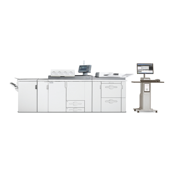
1.2 Names of Components BZS006 1. Toner hopper cover 2. Inner cover (cleaning unit for intermediate transfer belt) 3. Inner cover (development unit drawer) 4. Control panel 5. Front top cover 6. LCT front cover 7. Right front cover 8. Left front cover Parts, Screw Color Codes •... -
Page 12: Control Panel
1.3 Control Panel Pro C901S BZS001 1. Number keys 2. Operation switch 3. User Tools key 4. Counter key 5. Start key... - Page 13 Pro C901 BZS002 1. Number keys 2. Operation switch 3. User Tools key 4. Counter key 5. Start key...
-
Page 14: Common Procedures
2. Common Procedures 2.1 Turn the Machine off Before Beginning Any Procedure! WARNING • To prevent electrical shock, turn off the main power switch and disconnect the ground wire from the machine and fixing heater. Before performing any procedure shown in this manual, always do the following: 1. -
Page 15: Specifying System Auto-Reset Timer
2.2 Specifying System Auto-Reset Timer To prevent the machine switching screens while you are replacing parts, set [System Auto Reset Timer] to "Off". Once work is finished, return the setting to "On", if necessary. Note: For details about changing this setting, see General Settings Guide, which is supplied with this machine. -
Page 16: Displaying The [Adjustment Settings For Skilled Operators] Button
2.3 Displaying the [Adjustment Settings for Skilled Operators] Button To use the Adjustment Settings for Skilled Operators menu, you must first configure your machine's Administrator Authentication Management setting. 1. Press the [User Tools] key on the control panel. BZS003 2. Press [System Settings] on the display. 3. - Page 17 5. Press [Administrator Authentication Management]. 6. Press [Machine Management]. 7. Select [On] for "Admin. Authentication". 8. Press [OK]. 9. Press [Exit]. The [Adjustment Settings for Skilled Operators] button appears.
-
Page 18: Accessing The Adjustment Settings For Skilled Operators
2.4 Accessing the Adjustment Settings for Skilled Operators 1. Press [Adjustment Settings for Skilled Operators]. If the [Adjustment Settings for Skilled Operators] key does not appear, follow the procedure under "Displaying the [Adjustment Settings for Skilled Operators] Button" on p.16. 2. - Page 19 4. Enter your login password, and then press [OK]. The screen appears for Adjustment Settings for Skilled Operators.
-
Page 20: Resetting The Replaceable Parts Counter
2.5 Resetting the Replaceable Parts Counter 1. Access the Adjustment Settings for Skilled Operators menu. 2. Press [ Next]. 3. Press [Reset Replaceable Parts Counter]. 4. Press the button of the part that has been replaced. 5. Press [OK]. The counter for the replaced component is reset. The setting for adjusting the machine for the replaced component is executed automatically. -
Page 21: Removing The Front Top Cover
2.6 Removing the Front Top Cover Procedure 1. Open the left (2) and right (1) front covers. bzs124 2. Open the toner hopper cover (1). bzs123 Remove the two screws at (1) and (2) by hand. Note: Use a coin to turn the screws if they are too tight to turn by hand. Lift up the front top cover (3) and remove it. -
Page 22: Reattaching The Front Top Cover
2.7 Reattaching the Front Top Cover Procedure 1. Hold the front top cover. 2. Align the two tabs (1) on the bottom of the front top cover with the two cutouts (2) on the frame of the machine, and then hook the front top cover. 3. -
Page 23: Charger
3. Charger 3.1 Removing the Charger What You Need • Accessory hex screwdriver provided with the machine. • Newspaper or other paper covering a nearby flat surface on which you can place removed components. WARNING • To prevent electrical shock, turn off the main power switch and disconnect the ground wire from the machine and fixing heater. - Page 24 Procedure Open the left and right front covers. Remove the front top cover (See p.21 "Removing the Front Top Cover") Hold the charger (1) with the lock lever (2) pressed down. RPG023 bzs125 4. Carefully pull the charger (1) toward you. RPG024 5.
- Page 25 Important: To protect the charger from fingerprints, scratches, and dust: • Always hold the charger (1) with both hands. • Never touch the wire mesh (2) below. • Never allow anything to touch the wire mesh while the charger is outside the machine.
-
Page 26: Reinstalling The Charger
3.2 Reinstalling the Charger Important: To protect the charger from fingerprints, scratches, and dust: • Never touch the wire mesh on the underside of the charger. • Never allow anything to touch the wire mesh while the charger is outside the machine. -
Page 27: Cleaning Unit For Pcu
4. Cleaning Unit for PCU 4.1 Removing the Cleaning Unit for PCU What You Need • Accessory hex screwdriver provided with the machine. • Newspaper or other paper covering a nearby flat surface on which you can place removed components. WARNING •... - Page 28 4. Remove the inner cover (2) of the development unit drawer. RPG026 5. Loosen the drawer stop knob (1) by turning it counterclockwise, and then remove it. RPG027 6. Holding the purple handle (1), carefully pull out the development unit drawer. RPG028 Important: Do not leave the development unit drawer open for a long time.
- Page 29 7. Turn the lock lever (1) of the cleaning unit for PCU counterclockwise. RPG029 8. Grasping both sides (1) of the cleaning unit for PCU as shown, lift the cleaning unit for PCU (2) straight up. RPG007S 9. To avoid spilling toner, always carry the cleaning unit for PCU level with the exposed roller (1) facing up (not down).
-
Page 30: Reinstalling The Cleaning Unit For Pcu
4.2 Reinstalling the Cleaning Unit for PCU Procedure Note: If you want to replace the drum unit with the cleaning unit for PCU, see p.33 "Drum Unit". 1. Check the direction of the cleaning unit for PCU for reinstalling. • The waste toner collection pipe (1) should be at rear side. RPG018S 2. - Page 31 4. Gently and firmly push the purple handle (2) into the machine until the drawer can go no further and locks into place. RPG032 Important: Do not pinch the harnesses (1) on the frame when pushing the development unit drawer into the machine. RPG036 5.
- Page 32 Turn the machine's main power switch to ON, close the left and right front covers, and then wait for the machine to warm up. Access the Adjustment Settings for Skilled Operators menu. (See p.18 "Accessing the Adjustment Settings for Skilled Operators".) Reset the replaceable parts counter for the replaced cleaning unit for PCU.
-
Page 33: Drum Unit
5. Drum Unit 5.1 Removing the Drum Unit What You Need • Accessory hex screwdriver provided with the machine. • Newspaper or other paper covering a nearby flat surface on which you can place removed components. WARNING • To prevent electrical shock, turn off the main power switch and disconnect the ground wire from the machine and fixing heater. - Page 34 Procedure Open the left and right front covers, open the hopper cover, and then remove the front top cover. (See p.21 "Removing the Front Top Cover".) Remove the charger. (See p.23 "Removing the Charger".) Remove the cleaning unit for PCU. (See p.27 "Removing the Cleaning Unit for PCU".) Turn the drum lock nut (1) counterclockwise, and unlock the drum unit.
-
Page 35: Reinstalling The Drum Unit
5.2 Reinstalling the Drum Unit Procedure Important: Never touch the green area of the drum. 1. Set the new drum unit (1) in the development unit drawer, and make sure that the two guides (2) (front) (3) (rear) at the development unit drawer are inserted securely in the grooves (4) (front) (5) (rear) at the drum unit. - Page 36 3. Using the powder pad applicator, pat the surface of the drum lightly. RPG019S Important: • Setting powder must cover at least 25% of the surface of the drum to prevent damage to the cleaning unit for PCU and the drum. •...
- Page 37 Turn the machine's main power switch to ON, close the left and right front covers, and then wait for the machine to warm up. Access the Adjustment Settings for Skilled Operators menu. (See p.18 "Accessing the Adjustment Settings for Skilled Operators".) Reset the replaceable parts counter for the replaced drum unit.
-
Page 38: Developer
6. Developer 6.1 Removing the Used Developer Overview You can remove the developer from more than one development unit at a time. Important: Dispose of the developer bottle in accordance with the disposal regulations in your area. What You Need •... - Page 39 Procedure Open the left and right front cover, open the toner hopper cover, and then remove the front top cover. (See p.21 "Removing the Front Top Cover".) Check that the developer you are preparing is the correct color by looking at the combination of the raised markings (1) on the shutter of the developer bottle.
- Page 40 6. Push the developer bottle in the direction of the arrow (1) until it can go no further and locks into place. bzs157 Access the Adjustment Settings for Skilled Operators menu. (See p.18 "Accessing the Adjustment Settings for Skilled Operators".) Press [Developer Exhaust].
- Page 41 Disconnect the developer bottle from the developer outlet contact, and then remove it. Important: Cover surrounding surfaces with paper. This will prevent spillage from the developer bottle spoiling them. Remove the seal (1) that is stuck to the developer bottle. bzs150 15.
-
Page 42: Adding New Developer
6.2 Adding New Developer Important: Be sure to switch the machine on before beginning this procedure. This procedure requires the machine to be powered. Procedure 1. Check that the developer you are preparing is the correct color by looking at the combination of the raised markings (1) on the shutter of the developer bottle. - Page 43 4. Push the developer bottle in the direction of the arrow (1) until it can go no further and locks into place. bzs135 5. Pull the seal (1) completely away. RPG050 Access the Adjustment Settings for Skilled Operators menu. (See p.18 "Accessing the Adjustment Settings for Skilled Operators".) Press [Developer Fill].
- Page 44 11. While pressing the lock levers on either side of the developer bottle, carefully pull the bottle toward you. bzs136 Disconnect the developer bottle from the contact on the developer inlet, and then remove it. Turn the developer bottle upside down. Reattach the front top cover and close the toner hopper cover.
-
Page 45: Cleaning Unit For Intermediate Transfer Belt
7. Cleaning Unit for Intermediate Transfer Belt Removing the Cleaning Unit for Intermediate Transfer Belt What You Need • Accessory hex screwdriver provided with machine. • Newspaper or other paper covering a nearby flat surface on which you can place removed components. - Page 46 Procedure Open the left and right front covers. Remove the two black screws (1) on the inner cover (2) for the cleaning unit for intermediate transfer belt using the hex screwdriver. Remove the inner cover (2). Note: To remove the inner cover, pull it out and slightly upward. RPG044 Remove the black screw (1) on the cleaning unit for intermediate transfer belt using the hex screwdriver.
- Page 47 6. Using the handle (1), carefully pull the cleaning unit for intermediate transfer belt toward you until it can go no further. bzs160 7. While pressing down the lock tab (1), carefully pull out the cleaning unit for intermediate transfer belt. bzs161 Important: To avoid toner spillage while handling the cleaning unit for intermediate transfer belt, always keep the cleaning unit level.
-
Page 48: Installing The Cleaning Unit For Intermediate Transfer Belt
7.2 Installing the Cleaning Unit for Intermediate Transfer Belt Procedure 1. While holding the cleaning unit for intermediate transfer belt with both hands, set the cleaning unit for intermediate transfer belt (1) on its rails (2), and then carefully push it in until it can go no further. RPG041 RPG040 2. - Page 49 8. Press [OK]. Wait a while. The message "The setting(s) will be applied. Please wait." should disappear after about five minutes. Reset the replaceable parts counter for the cleaning unit for intermediate transfer belt. (See p.20 "Resetting the Replaceable Parts Counter".) Open the left and right front covers.
-
Page 50: Transfer Unit
8. Transfer Unit 8.1 Removing the Transfer Unit What You Need • Accessory hex screwdriver provided with machine. • Newspaper or other paper covering a nearby flat surface on which you can place removed components. WARNING • To prevent electrical shock, turn off the main power switch and disconnect the ground wire from the machine and fixing heater. - Page 51 Using the hex screwdriver, remove the black screw in the rear lock (1), and then slide the rear lock to the rear end. Using the hex screwdriver, remove the black screw in the front lock (2), and then slide the front lock to the front end. RPG065S 5.
-
Page 52: Installing The Transfer Unit
8.2 Installing the Transfer Unit Procedure While holding the transfer unit (1) with both hands, align the stays (2) of the transfer unit with the shafts of the registration unit drawer, and then set the transfer unit on the registration unit drawer. Slide the rear lock (3) forward to align it with the shaft screw hole. - Page 53 4. Using the hex screwdriver, turn the black screws to lock the front (1) and rear (2) locks. RPG068S RPG067S Carefully the registration unit drawer into the machine until it can go no further and locks into place. Rotate the lock lever (1) of the registration unit drawer clockwise. RPG043 Reconnect the ground leakage circuit breaker for the machine and fixing heater.
-
Page 54: Fusing Unit
9. Fusing Unit 9.1 Removing the Fusing Unit WARNING • To prevent electrical shock, turn off the main power switch and disconnect the ground wire from the machine and fixing heater. • The fusing unit becomes extremely hot during operation, so to prevent minor burns, turn the machine off and allow it to cool for at least 30 minutes before you remove the fusing unit. - Page 55 Procedure 1. Open the left and right front covers. Important: Be sure to open both the right and left front covers. You could damage the right cover if you remove the fusing unit with the right cover closed. bzs124 2. Remove the handle for replacing the fusing unit; this is stowed in a recess at the bottom left of the machine.
- Page 56 4. Using the hex screwdriver, remove the black screw on the fusing unit. bzs102 5. Attach the handle to the fusing unit. bzs153 6. Tilt the projecting part to the left to raise the handle. bzs103 Touch the projecting part only, because the fusing unit is hot.
- Page 57 7. With another person, hold the handle of the fusing unit, and then detach the fusing unit by lifting it up and out. bzs104 8. Set the fusing unit down on its base.
-
Page 58: Reinstalling The Fusing Unit
9.2 Reinstalling the Fusing Unit Procedure 1. Detach the handle from the used fusing unit, and then attach the handle to the new fusing unit. 2. With another person, hold the new fusing unit by its handle and then position the unit so that the triangular markings are aligned, and then place the end of the unit into the guide rail. - Page 59 7. Stow the handle in the recess at the bottom left of the machine. bzs152 8. Reconnect the ground leakage circuit breaker for the machine and fixing heater. 9. Turn the machine's main power switch to ON, close the left and right front covers, and then wait for the machine to warm up.
-
Page 60: Toner Filter
10. Toner Filter 10.1 Removing the Used Toner Filter Caution • When removing used toner filter, avoid getting toner (new or used) on your skin. If toner comes into contact with your skin, wash the affected area thoroughly with soap and water. Hot water will set the toner into the fabric and make removing the stain impossible. - Page 61 Preparation: Print out the counter list. Press the [Counter] key on the control panel (see p.12 "Control Panel") and print out the counter list. Turn the machine off. (See p.14 "Turn the Machine off Before Beginning Any Procedure!") Procedure 1. Using the hex screwdriver, remove the five black screws on the back of the machine.
- Page 62 3. Unlock the toner filter cover by pulling the locks on its sides toward you, and then remove the cover. bzs109 4. Pull out the toner filter. bzs110 5. When removing the used toner filters for cyan, magenta, and yellow, perform steps 3 and 4 for all three colors.
-
Page 63: Installing The Toner Filter
10.2 Installing the Toner Filter Procedure 1. Install the new toner filter. 2. Push in the toner filter cover until it clicks. 3. Engage the bottom of the rear upper cover and align the three hooks at the top of the cover with the corresponding catches. bzs111 4. - Page 64 5. Using the hex screwdriver, replace the five black screws. bzs107 6. Reconnect the ground leakage circuit breaker for the machine and fixing heater. 7. Turn the machine's main power switch to ON, and then wait for the machine to warm up.
-
Page 65: Paper Feed Roller Replacement
11. Paper Feed Roller Replacement 11.1 Before You Begin Read this section before attempting to replace the paper feed rollers. Tray Naming The paper feed trays of the Wide LCT are sometimes referred to by number, so use the following illustration to identify the trays. BZS004 Trays 3 and 4 are the top and bottom trays of the first Wide LCT. -
Page 66: Paper Feed Rollers
Paper Feed Rollers There are three rollers, and the construction of each roller is different. bzs131 Pick-up roller: This roller pulls one sheet of paper out of the tray and feeds it to the feed roller. Attach it to shaft a'. Feed roller: This roller feeds the paper from the tray into the paper path. - Page 67 What You Need • Accessory hex screwdriver provided with machine. Message for Replacement Replacement of Paper Feed Roller (XXX) is now necessary. Replace Paper Feed Roller (XXX). "XXX" indicates the number of the paper feed tray. If this message appears, replace the unit according to the following procedure: Preparation: Print out the counter list.
-
Page 68: Wide Large Capacity Tray
11.2 Wide Large Capacity Tray Tray 3/Tray 5 (Top Tray) 1. Open the LCT front cover. bzs113 2. Pull out Tray 3/Tray 5 until it stops. If there is any paper in the tray, remove it. 3. Using the provided accessory hex screwdriver, remove the two black screws, and then remove the side plate. - Page 69 5. Using the hex screwdriver, remove the black screw from the bracket. bzs116 6. Slide the bracket to the left so you can reach the rollers. 7. Remove the three snap rings, and then remove each roller. bzs117 8. Attach the new rollers, and then secure them with the snap rings. 9.
- Page 70 11. Reattach paper feed unit U2 with the two black screws. bzs119 12. Align the markers at (1) and (2), and then set the side plate. bzs120 13. Reattach the two black screws to the side plate. 14. Push Tray 3/Tray 5 back inside the machine. 15.
- Page 71 Tray 4/Tray 6 (Bottom Tray) 1. Open the LCT front cover. bzs129 2. Pull out Tray 4/Tray 6 until it stops. If there is any paper in the tray, remove it. 3. Using the provided accessory hex screwdriver, remove the two black screws, and then remove the side plate.
- Page 72 5. Using the hex screwdriver, remove the black screw from the bracket. bzs116 6. Slide the bracket to the left so you can reach the rollers. 7. Remove the three snap rings, and then remove each roller. bzs117 8. Attach the new rollers, and then secure them with the snap rings. 9.
- Page 73 10. Push paper feed unit U4 into the machine. If you cannot fully insert unit U4, turn lever U4 counterclockwise while pushing in the unit. 11. Reattach paper feed unit U4 with the two black screws. bzs130 12. Align the markers at (1) and (2), and then set the side plate. bzs120 13.
- Page 74 M077-9601...
Need help?
Do you have a question about the Pro C901S and is the answer not in the manual?
Questions and answers