socomec Modulys GP Green Power 2.0 Series Installation And Operating Manual
100 kw ul ups
Hide thumbs
Also See for Modulys GP Green Power 2.0 Series:
- Installation manual (54 pages) ,
- Installation and operating manual (48 pages)
Table of Contents
Advertisement
Advertisement
Table of Contents

Subscribe to Our Youtube Channel
Related Manuals for socomec Modulys GP Green Power 2.0 Series


Summary of Contents for socomec Modulys GP Green Power 2.0 Series
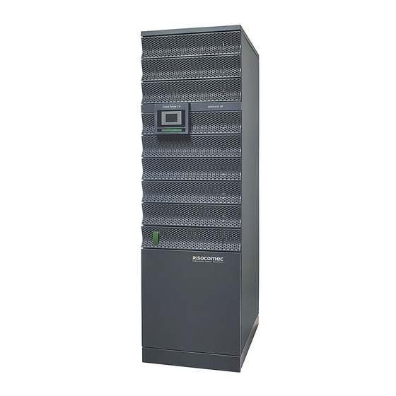
- Page 1 MODULYS GP Green Power 2.0 range 100 kW UL www.socomec.com...
-
Page 3: Table Of Contents
CONTENTS 1. SAFETY STANDARDS 1.1 IMPORTANT SAFETY INSTRUCTION ........5 1.2 DESCRIPTION OF SYMBOLS . - Page 4 SOCOMEC retains the full and exclusive ownership rights to this document. Only a personal entitlement to use the document for the application indicated by SOCOMEC is granted to the recipient of this document. The reproduction, modification, distribution of this document, either partially or wholly and in any manner, is strictly prohibited except upon Socomec’s express prior written consent.
-
Page 5: Safety Standards
CAUTION! If the unit is found to be damaged externally or internally, or any of the accessories are damaged or missing, contact SOCOMEC. Do not operate the unit if it has suffered a violent mechanical shock of any kind. NOTE! Install the unit in accordance with clearances in order to prevent access to handling devices and guarantee sufficient ventilation (refer to 'Environmental requirements' chapter). -
Page 6: Description Of Symbols
Connecting accumulators in series creates hazardous voltages. We advise you to contact SOCOMEC beforehand to confirm the ability of these products to meet the required level of safety, performance, reliability and compliance with applicable laws, regulations and specifications. Operating modes 'MODULYS GP' 100 kW UL - Ref.: IOMMODGPXX09-EN 03... -
Page 7: Bbreviations
1.3 BBREVIATIONS For the purpose of this document, the following abbreviations are used: Battery Management System Electro Magnetic Compatibility Human Machine Interface International Electrotechnical Commission Insulation Monitoring Device Li-Ion battery MBMS Master BMS Protective Earth State of Charge State of Health Surge Protection Device THDI Total Harmonic Distortion in Current... -
Page 8: Environmental Requirements And Handling
2. ENVIRONMENTAL REQUIREMENTS AND HANDLING NOTE! Before carrying out any operations on the unit read the 'Safety standards' chapter carefully. 2.1 ENVIRONMENTAL REQUIREMENTS The room must be: • of a suitable size • free from conductive, inflammable and corrosive items; •... -
Page 9: Handling
IN-ROW CONFIGURATION Top view Front view hot aisle free area SERVER SERVER SERVER SERVER OR OTHER OR OTHER OR OTHER OR OTHER CABINET CABINET CABINET CABINET SERVER SERVER SERVER SERVER OR OTHER OR OTHER OR OTHER OR OTHER CABINET CABINET CABINET CABINET 130°... -
Page 10: Electrical Installation
3. ELECTRICAL INSTALLATION NOTE! Before carrying out any operations on the unit read the 'Safety standards' chapter carefully 3.1 ELECTRICAL REQUIREMENTS The installation and system must comply with national plant regulations. The electrical distribution panel must have a sectioning and protection system installed for input mains. If a RCD is required a B-type should be used. - Page 11 BACKFEED PROTECTION The UPS is set up for the installation of external protection devices against the backfeed of dangerous voltages on the auxiliary backup mains power supply line (AUX MAINS SUPPLY). The current rating of the switching device has to follow the instruction outlined in chapter 'Electrical requirements'.
-
Page 12: Cable Positioning
3.2 CABLE POSITIONING WARNING! The cables must be installed on trays according to the following diagrams. The trays must be positioned near the UPS. WARNING! All metal and suspended ducts or those in raised flooring MUST be connected to earth and to the various cabinets WARNING! Power cables and control cables MUST NEVER be installed in the same duct. -
Page 13: Overview
4. OVERVIEW MODULYS GP front view Slots not available Control panel Slots for power modules only UPS door Operating modes 'MODULYS GP' 100 kW UL - Ref.: IOMMODGPXX09-EN 03... - Page 14 SYSTEM WITH MANUAL BYPASS AND INPUT, AUX MAINS, OUTPUT SWITCHES USB connector (only for service) Ethernet network (only for service) Option slot 1 Hot-swap bypass Option slot 2 Over voltage protection Q1 (Input mains switch) Q3 (output switch) Fuse Service connection UPS connections Service Fuse WIRING DIAGRAM...
-
Page 15: Connections
5. CONNECTIONS NOTE! Before carrying out any operations on the unit read the 'Safety standards' chapter carefully. WARNING! Battery power terminals can be supplied by: - external battery cabinet; - internal battery modules; - UPS power modules. Before working on this circuit ensure that: - all the external battery cabinet switches are in OFF position;... - Page 16 EXTERNAL BATTERY MAINS SUPPLY OUTPUT PROTECTIVE EARTH TERMINAL Operating modes 'MODULYS GP' 100 kW UL - Ref.: IOMMODGPXX09-EN 03...
-
Page 17: External Battery Connection
5.1 EXTERNAL BATTERY CONNECTION NOTE! For further information refer to the battery cabinet manual. • Remove the plastic terminal block protection. • Connect the protective earth (PE) cable. • Connect the cables between the UPS terminals and the battery cabinet terminals. WARNING! Strictly observe: - the polarity of each individual string (refer to the figure below);... -
Page 18: Power And Bypass Module Insertion
5.2 POWER AND BYPASS MODULE INSERTION Note! Before carrying out any operations on the unit read the 'Safety standards' chapter carefully. WARNING! RISK OF TIPPING OVER! Before carrying out any operations, ensure the UPS is secured at the feet. WARNING! RISK OF TIPPING OVER! The six feet must be secured evenly to ensure the unit is stable. - Page 19 POWER MODULE INSERTION WARNING! Ensure the module is installed in the correct position. Operating modes 'MODULYS GP' 100 kW UL - Ref.: IOMMODGPXX09-EN 03...
- Page 20 POWER MODULE REMOVAL Operating modes 'MODULYS GP' 100 kW UL - Ref.: IOMMODGPXX09-EN 03...
- Page 21 BYPASS MODULE REPLACEMENT WARNING! It is only possible to remove the bypass module when the unit is in normal mode or in mainte- nance bypass mode (refer to 'Operating modes' chapter). Before removing the bypass ensure that the unit is not in bypass mode. Operating modes 'MODULYS GP' 100 kW UL - Ref.: IOMMODGPXX09-EN 03...
- Page 22 WARNING! The screws provide protective bonding and avoid unauthorised bypass removal. Tighten the screws to ensure the bonding protection. DANGER! Failure to observe this safety instruction could result in fatal accident or serious injury, and damage equip- ment or the environment. Operating modes 'MODULYS GP' 100 kW UL - Ref.: IOMMODGPXX09-EN 03...
-
Page 23: Control Panel
6. CONTROL PANEL Power module LED indicators Luminous status bar Bypass module LED indicator LED indicator Colour Power module Bypass module Green Module on inverter Bypass ready to start Flashing green Load on bypass Yellow Module ready to start Maintenance bypass Load on inverter or bypass and transfer impossible/ Flashing yellow Module initialising... - Page 24 CONTROL PANEL EXTRACTION Display HOME button Luminous status bar Operating modes 'MODULYS GP' 100 kW UL - Ref.: IOMMODGPXX09-EN 03...
- Page 25 Only two elements are necessary to interact with the unit: • HOME button: is a mono-stable button used to interact manually with the display especially in emergency situa- tions. Logic behind the interaction is: - Single pressing (below 3 sec): HOME page return of graphic display - 3 sec <...
-
Page 26: Display Operation
7. DISPLAY OPERATION 7.1 DISPLAY DESCRIPTION • Stand alone UPS or unit view • Modules view: Menu access Device reference Functioning mode (see 'Functioning mode' chap- ter) Status displaying / Status page access Alarm present – access to alarm page “Alarms”... -
Page 27: Menu Architecture
7.2 MENU ARCHITECTURE MENU ITEMS Modular Unit Modular Unit Modular System [UPS] [1] to [3] [SYS] MONITORING ▶ ALARMS • • • ▶ STATUS • • • ▶ SYNOPTIC • ▶ UNIT • • ▶ SYSTEM • • ▶ MODULES OVERVIEW •... - Page 28 CONFIGURATIONS ▶ CLOCK • • ▶ COM-SLOTS ▶ COM-Slot 1 ▶ COM-Slot 2 ▶ TEMPERATURE PROBE ▶ REFERENCE ▶ SOCOMEC REFERENCE • • ▶ SERIAL NUMBER • • ▶ User Reference • ▶ Location • ▶ REMOTE ▶ Remote ON •...
- Page 29 MENU ITEMS Modular Unit Modular Unit Modular System [UPS] [1] to [3] [SYS] SERVICE ▶ SERVICE REPORT • • ▶ FW VERSION • • ▶ UPS SETTINGS ▶ OUTPUT MENU ▶ Output voltage • • ▶ Output frequency • • ▶...
- Page 30 MENU ITEMS Modular Unit Modular Unit Modular System [UPS] [1] to [3] [SYS] ▶ TRANSFORMER MENU ▶ Input transformer • • ▶ Output transformer • • ▶ Aux transformer • • ▶ Input trasfo Voltage • • ▶ Output trasfo Voltage •...
-
Page 31: Functioning Mode
7.3 FUNCTIONING MODE Service Isolated Eco mode scheduling active Eco Mode active Standby active Energy saver active Autotest 7.4 STATUS 7.4.1 STATUS PAGE Filtering List all active status List all status List all status not active Operating modes 'MODULYS GP' 100 kW UL - Ref.: IOMMODGPXX09-EN 03... -
Page 32: Alarms Management
7.5 ALARMS MANAGEMENT 7.5.1 ALARM REPORT The alarm icon is present if at least one alarm is present. Tap on the icon to open the alarm list. 7.5.2 ALARM POPUP In case of critical alarm a popup message appears and the buzzer is running according its settings. The highest priority alarm is displayed. -
Page 33: Synoptic Animation
7.6 SYNOPTIC ANIMATION • Stand alone UPS or unit view • UPS parallel system: System view Operating modes 'MODULYS GP' 100 kW UL - Ref.: IOMMODGPXX09-EN 03... - Page 34 Rules of animation Item Description Touch actions Grey Green Yellow Out of toler- Rectifier input supply Not present Present ance Normal Preventive Critical alarm Access to input status alarm Rectifier status measurements page DC voltage DC voltage DC voltage bus absent presence Normal...
- Page 35 • UPS parallel system: Units overview Module number Unit selected Load report Battery report Operating modes 'MODULYS GP' 100 kW UL - Ref.: IOMMODGPXX09-EN 03...
- Page 36 • Battery animation Battery status DESCRIPTION If battery is absent, the battery icon is not displayed If battery is present but not connected, the icon is displayed If the battery is present and charging, the arrow icon is displayed If the battery is present and discharging, the arrow icon is displayed If a battery alarm has occurred, the red icon is displayed...
-
Page 37: Additional Icons
7.6.1 ADDITIONAL ICONS Bypass impossible Bypass locked “Genset Mode” when the gen set contact is active. Need ADC+SL correctly configured. Maintenance alarm. Preventive maintenance is requested. 7.7 EVENT LOG PAGE Show STATUS events Show ALARMS events Show CONTROLS Operating modes 'MODULYS GP' 100 kW UL - Ref.: IOMMODGPXX09-EN 03... -
Page 38: Menu Function Descriptions
7.8 MENU FUNCTION DESCRIPTIONS 7.8.1 ENTERING PASSWORDS Some operations and settings require a password in order to be performed. Press “123” to cycle to number view page. Press ENTER to confirm. Wildcard covering of the password is active by default. The default password is SOCO. -
Page 39: Ups Configuration Menu
7.8.6 UPS CONFIGURATION MENU • CLOCK: this function sets the date and time. • COM-SLOTS: this function configures the RS485 modbus serial link. • REFERENCE: this function gives the possibility to customised the unit reference and the location. • REMOTE: this function enables controls from remote devices through MODBUS protocol (NET VISION for exam- ple). -
Page 40: Additional User Functions
7.9 ADDITIONAL USER FUNCTIONS 7.9.1 PHASE COLOR MODIFICATION • Enter MAIN MENU > USER PARAMETERS > PREFERENCES For each phase is possible to select a specific colour in a set of colour range. Those colours are applying in the measurements pages. Colour Default colour Yellow... -
Page 41: Operating Procedures
8. OPERATING PROCEDURES NOTE: before carrying out any operations on the unit read the 'Safety standards' chapter care- fully. NOTE: with the stop procedure the load will be disconnected. 8.1 SWITCHING ON • Connect the mains to the UPS. • Put switch Q1 (or the external input mains switching device) into position 1. •... -
Page 42: Extended Out Of Service
SWITCHING ON FROM MAINTENANCE BYPASS • Put the external manual bypass switch to position 0. WARNING! This operation interrupts the power supply to the load. • Put switch Q1 (or the external input mains switching device) into position 1. • Wait for the display to switch on. •... -
Page 43: Operating Modes
9. OPERATING MODES 9.1 ON LINE MODE A special feature of the UPS is the ONLINE double conversion in conjunction with low distortion mains power absorp- tion. In ON LINE mode, the UPS can supply a voltage that is fully stabilised in frequency and amplitude, regardless of any interference in the mains power supply, within the most stringent classification of UPS regulations. -
Page 44: Standard Features And Options
10. STANDARD FEATURES AND OPTIONS Availability ⚫ Factory-installed option ⚪ Available as option ─ Not available Features MODULYS GP Compatibility Communication Option ⚪ ADC+SL card ⚪ Temperature sensor ADC+SL card ⚪ Net Vision card ⚪ Net Vision card ⚪ Li-ion battery interactivity kit ADC+SL card ⚪... -
Page 45: Adc+Sl Card
10.1 ADC+SL CARD The ADC+SL (Advanced Dry Contact + Serial Link) is a slot optional board that provides: • 4 relays for external device activation (can be set as normally closed or normally open). • 3 free inputs to report external contacts to UPS. •... - Page 46 1. The acronyms mentioned are linked to MODBUS table (Snnn=Status/Annn=Alarm). 2. A self-locking emergency push button must be used for the UPS Power Off input. Note: custom configuration is also available. For more information contact Socomec. Operating modes 'MODULYS GP' 100 kW UL - Ref.: IOMMODGPXX09-EN 03...
- Page 47 NOTE! Inputs and relays can be re-programmed depending on requirements. Contact your SOCOMEC after-sales service to change Input/Output programming. Information coming from inputs can be reported in the UPS database for display on the mimic panel and is accessible on the MODBUS table.
-
Page 48: Temperature Sensor
The RS485 provides MODBUS RTU protocol. The description of MODBUS addresses and UPS database are described in the MODBUS user manual. All manuals are available on SOCOMEC’s web site (www.socomec.com). SERIAL LINK SETTINGS COM1 relates to serial port on board in SLOT 1. -
Page 49: Net Vision Card
10.2 NET VISION CARD NET VISION is a communication and management inter- face designed for business networks. The UPS behaves exactly like a networked peripheral, it can be managed remotely, and allows the shutdown of network worksta- tions. NET VISION allows a direct interface between the UPS and LAN network avoiding dependence on the server and support SMTP, SNMP, DHCP and many other protocols. -
Page 50: Top Air Exhausted
10.4 TOP AIR EXHAUSTED 10.5 TOP ENTRY CABLES Operating modes 'MODULYS GP' 100 kW UL - Ref.: IOMMODGPXX09-EN 03... -
Page 51: Preventive Maintenance
Before carrying out any operations on the unit read the 'Safety standards' chapter carefully. NOTE! Any work carried out on the equipment must be performed by qualified technicians authorised by SOCOMEC. Routine maintenance carried out annually is recommended in order to provide optimum operating efficiency and avoid equipment downtime. -
Page 52: Safeguarding The Environment
12. SAFEGUARDING THE ENVIRONMENT Do not dispose of electrical appliances with normal waste, use separate collection facilities. Follow local council waste regulations for proper disposal arrangements to reduce the environmental impact of waste electrical and electronic equipment or contact your local government for information regarding the collection arrange- ments available. -
Page 53: Technical Specifications
13. TECHNICAL SPECIFICATIONS Number of modules Power Power Input Input mains voltage 3ph 480 V (+15/-15%) up to -40% @ 50% of nominal load Input mains frequency 60 +/-10% Input power factor ≥ 0.99 Total harmonic input current distor- ≤ 3% (@: Pn, Resistive load, Mains THDv ≤ 1%) tion (THDi) Output Output voltage (three phase) - Page 56 Socomec: our innovations supporting your energy performance 3,200 independent manufacturer employees % of sales revenue experts worldwide dedicated to R&D dedicated to service provision Your power management expert POWER POWER POWER EXPERT SWITCHING MONITORING CONVERSION SERVICES The specialist for critical applications...
Need help?
Do you have a question about the Modulys GP Green Power 2.0 Series and is the answer not in the manual?
Questions and answers