
Related Manuals for socomec ITYS 10 kVA


Summary of Contents for socomec ITYS 10 kVA
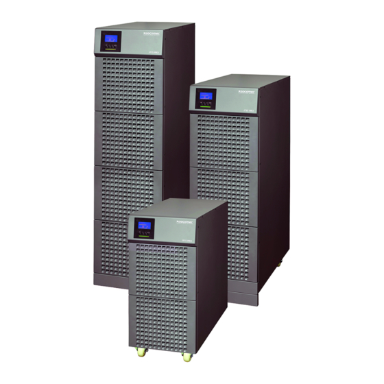
- Page 1 ITYS 1 0 - 2 0 k V A 安装及操作手册 Installations- und bedienungsanleitung Installation and operating manual Manual de instalación y uso Manuel d’installation et d’utilisation Manuale di installazione e uso...
- Page 2 WARRANTY CERTIFICATE AND CONDITIONS This SOCOMEC appliance is guaranteed against manufacturing and material defects for a period of 12 months from the date of purchase (local warranty conditions are applicable in addition to the general conditions). This warranty certificate should NOT be e-mailed, but kept by the customer along with proof of purchase, for use in the event of a claim being made for repairs or repla- cement under warranty.
-
Page 3: Table Of Contents
TABLE OF CONTENTS 1. SAFETY STANDARDS ............4 1.1. -
Page 4: Safety Standards
For such use it is advisable to contact SOCOMEC beforehand to confirm the ability of these products to meet the required level of safety, performance, reliability and compliance with applicable laws, regulations and specifications. -
Page 5: Description Of Symbols
1. SAFETY STANDARDS 1.1. DESCRIPTION OF SYMBOLS Accumulators are heavy! Use suitable transport and Wear safety goggles and suitable clothing. lifting equipment to work safely. Read the user instructions carefully. Connecting accumulators in series creates hazar- Read the user manual before performing any opera- dous voltages. -
Page 6: Installation
If the unit is found to be damaged externally or internally, or any of the accessories are damaged or missing, contact SOCOMEC. All packaging material must be recycled in compliance with the laws in force in the country where the system is installed. -
Page 7: Notes For Installation
2. INSTALLATION 2.3. NOTES FOR INSTALLATION Ensure the air vents on the front and rear of the UPS are not blocked. Allow at least 0.5 m of space on each side. Once the installation is completed, the side mounting brackets (used in shipping) shall be fixed back to ensure the stability of the UPS enclosure. -
Page 8: Electrical Requirements
3. ELECTRICAL REQUIREMENTS The installation and system must comply with national plant regulations. The electrical distribution panel must have a protection and sectioning system installed for the input mains and auxiliary mains. If a differential switch is installed on the mains power switch (optional) it must be inserted upstream from the distribution panel. -
Page 9: Rear View
RS232 serial connector USB serial port EPO (Emergency Power Off) Slot for optional AUX slot communication boards Fans Backfeed cover Neutral switch cover Manual bypass Input breakers Input and output terminal board ITYS 10 kVA ITYS 10-20 kVA - Ref.: IOMITYTWXX0C-GB 00... - Page 10 4. REAR VIEW RS232 serial connector USB serial port EPO (Emergency Power Off) Slot for optional AUX slot communication boards Fans Fans Backfeed cover Neutral switch cover Manual bypass Input breakers Input and output terminal board ITYS 20 kVA ITYS 10-20 kVA - Ref.: IOMITYTWXX0C-GB 00...
-
Page 11: Connections
5. CONNECTIONS The installation and the system must comply with national plant regulations. If a diff erential switch is installed on the mains power switch (optional) it must be inserted upstream from the distribution panel. CAUTION! Use selective differentials. Any current dispersed by the loads will be summed to that of the UPS. The differential protection must be regulated in cases of loads with high current dispersion. -
Page 12: Operation In High Efficiency Mode
5. CONNECTIONS Sigle phase connection Three phase connection External distribution panel UPS input External distribution panel UPS input All cables must be securely connected. 5.1. OPERATION IN HIGH EFFICIENCY MODE The UPS has a selectable, programmable economy operating mode that can increase overall efficiency by up to 98% for energy saving purposes. -
Page 13: Mimic Panel
6. MIMIC PANEL Battery Bypass mode (yellow) (yellow) Normal mode Fault (red) (green) ON/OFF Enter Up/Exit Down 1. Press for 1 second Bypass Output Load Output load Battery status Input Alert icon Inverter ITYS 10-20 kVA - Ref.: IOMITYTWXX0C-GB 00... -
Page 14: Operating Modes
7. OPERATING MODES 7.1. SWITCHING THE ITYS ON 7.1-3 7.1-1 7.1-2 5 sec 7.1-4 7.1-5 7.2. SWITCHING THE ITYS OFF 7.2-1 7.2-2 7.2-3 5 sec 7.2-4 7.2-5 7.2-6 Wait for complete shutdown. ITYS 10-20 kVA - Ref.: IOMITYTWXX0C-GB 00... -
Page 15: Operating Modes
7. OPERATING MODES 7.3. OPERATING MODES 7.3-1 7.3-2 7.3-3 Line mode Battery mode UPS OFF 7.3-4 7.3-5 7.3-6 HE mode Converter Mode Manual Bypass 7.4. MENU TREE FIRST LEVEL SECOND LEVEL THIRD LEVEL UPS STATUS EVENT LOG OUTPUT OVERLOAD UTILITY ABNORMAL OVER CHARGER MEASUREMENTS OUTPUT... - Page 16 7. OPERATING MODES FIRST LEVEL SECOND LEVEL THIRD LEVEL IDENTIFICATION TYPE/MODEL SERIAL NUMBER UPS FIRMWARE SETTINGS USER PASSWORD enabled/disabled AUDIO ALARM enabled/disabled OUTPUT VOLTAGE 208/220/230/240 V OUTPUT FREQUENCY autosensing 50/60 Hz POWER STRATEGY normal/high effi ciency/ converter DC START enabled/disabled AUTOMATIC BATTERY TEST PERIOD 0 to 31days AUTO RESTART...
-
Page 17: Communication
8. COMMUNICATION Communication software and accessories are available for monitoring UPS status, with the aim of optimising normal operation and ensuring that shutdown at the end of backup time is managed correctly. Applications allow recording of all power outages and any depletion of battery power so as to enable the activation of an automatic procedure for closing programs in an ordered sequence and shutting down the system. -
Page 18: Troubleshooting
9. TROUBLESHOOTING If the UPS system does not operate correctly use the table below to try and solve the problem. Please have the following information at hand before calling the After-Sales Service Department: • Model number, serial number • Date on which the problem occurred •... - Page 19 10. TROUBLESHOOTING Alert code Problem Possible cause Solution Warning 86 Heatsink Over Temperature Internal UPS temperature of Check the ventilation of the UPS and ambient UPS too high temperature. Warning 92 Model Pin Error UPS internal fault Consult dealer. Fault 93 Backfeeder UPS internal fault Don’t touch any terminal of equipment which...
-
Page 20: Technical Specification
10. TECHNICAL SPECIFICATION Models 10 (LB) 20 (LB) Nominal Power VA/W 10000/9000 20000/18000 Input/Output phases 3/1 or 1/1 Electrical Specifications - Input Mains voltage (Vin) (110-276) VAC (Depends on Load Level) 3Ph+1N+PE, Bypass input Voltage(Vin) 220 V 1Ph+N Input frequency 50-60 Hz ±10% Input power factor >... - Page 22 Fax. +48 22 825 73 60 info.ups.pl@socomec.com HEAD OFFICE YOUR DISTRIBUTOR *IOMITYTWXX0C-GB 00* SOCOMEC GROUP S.A. SOCOMEC capital 10 816 800€ R.C.S. Strasbourg B 548 500 149 B.P. 60010 - 1, rue de Westhouse IOMITYTWXX0C-GB 02.2014 F-67235 Benfeld Cedex - FRANCE Tel.
Need help?
Do you have a question about the ITYS 10 kVA and is the answer not in the manual?
Questions and answers