Table of Contents

Subscribe to Our Youtube Channel
Related Manuals for Printronix P5005B


Summary of Contents for Printronix P5005B
- Page 1 User’s Manual The Printronix P5000 series Of Line Matrix Printers P5005B™, P5205B™, P5010™, P5210™, P5215™ Mantenimiento Periféricos Informáticos SL C/Canteras, 15 28860 Paracuellos de Jarama Tel: 00 34 917481604 WEB: https://mpi.com.es...
- Page 2 Printronix, Inc. or by network, by telephone, or electronically using any Printronix, Inc. If you fail to comply with the terms of this License means; or reverse engineer, decompile or disassemble and such failure is not corrected within thirty (30) days after notice.
- Page 3 User’s Manual 164299-001, Rev. E Mantenimiento Periféricos Informáticos SL C/Canteras, 15 28860 Paracuellos de Jarama Tel: 00 34 917481604 WEB: https://mpi.com.es...
-
Page 4: Trademark Acknowledgments
Printronix makes no representations or warranties of any kind regarding this material, including, but not limited to, implied warranties of merchantability and fitness for a particular purpose. Printronix shall not be held responsible for errors contained herein or any omissions from this material or for any damages, whether direct or indirect, incidental or consequential, in connection with the furnishing, distribution, performance, or use of this material. -
Page 5: Table Of Contents
Table of Contents 1 Introduction ..........9 Printer Overview ..............9 The Printer Family............9 Conventions In This Manual..........12 Warnings And Special Information........12 Related Documents............13 Graphics Enhancements..........14 Taking Care Of Your Printer..........14 Protocols And Emulations ..........15 2 Setting Up The Printer ......17 Before You Begin ..............17 Power Requirements ............17 Select A Site ................18... - Page 6 Table of Contents Install Basic Components ............38 Attach The Control Panel Overlays.......38 Load The Ribbon ............39 Load The Paper ............41 Install Optional Components ..........45 SureStak Power Paper Stacker ........45 Quick Access Cover (Pedestal Model)......50 Set The Top-of-Form ............51 Procedure ..............51 3 Operating The Printer ......
- Page 7 Table of Contents IGP/PGL Emulation .............93 Features ................93 Configuring The Emulation With The Control Panel ..94 Submenu...............95 IGP/VGL Emulation ............107 Features ..............107 Configuring The Emulation With The Control Panel ...108 Submenu..............109 EMULATION..............122 Menu ................122 Coax/Twinax Emulation .............123 Standard C/T Interface..........123 Simple Protocol Converter ..........124 Coax Emulation Menu..........125 Twinax Emulation Menu..........135...
- Page 8 Table of Contents IEEE 1284 Parallel (Bidirectional) Submenu....209 Ethernet Submenu ............211 ETHERNET PARAMETERS ..........212 Menu ................212 PRINTER CONTROL ............213 DIAGNOSTICS..............216 RIBBONMINDER...............219 5 Troubleshooting ........223 Cleaning Requirements .............223 Exterior Cleaning ............223 Interior Cleaning............224 Diagnosing Problems ............226 Bar Code Verification ..........226 Printing A Hex Dump...........226 Fault Messages............228 A Printer Specifications ......
-
Page 9: Introduction
This chapter provides a general overview of your printer and the conventions used within this manual. The Printer Family ® The Printronix P5000 series of Line Matrix Printers consists of 500, 1000, and 1500 lines per minute (lpm) models packaged in various configurations. All of the models offer software versatility and the latest refinements in line matrix printing technology. - Page 10 Chapter 1 Printer Overview ® LinePrinter Plus is the standard emulation. LinePrinter Plus ® includes the Epson FX-1050, Printronix P-Series, P-Series XQ, ® Serial Matrix and Proprinter III XL emulations. Coax/Twinax, ® ® ® IPDS , ANSI and the IGP...
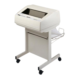
- Page 11 Table 1. The P5000 Family Model Print Hammer Quick Power Pedestal Cabinet Number Speed Bank Access Stacker á P5005B 500 lpm Standard á P5005B-12 500 lpm 12 MIL tips á á P5005B-QA 500 lpm Standard á á P5005B-12-QA...
-
Page 12: Conventions In This Manual
Chapter 1 Printer Overview Conventions In This Manual All uppercase print indicates control panel keys. Example: Press the CLEAR key, then press the ON LINE key. Quotation marks (“ ”) indicate messages on the Liquid Crystal Display (LCD). Example: Press the ON LINE key. “OFFLINE” appears on the LCD. -
Page 13: Related Documents
LinePrinter Plus Programmer's Reference Manual — Covers the host control codes for the LinePrinter Plus emulations. • IGP/PGL Programmer's Reference Manual — Provides information used with the optional IGP Printronix emulation enhancement feature. • IGP/VGL Programmer's Reference Manual — Provides... -
Page 14: Graphics Enhancements
Chapter 1 Printer Overview Graphics Enhancements The IGP/PGL and IGP/VGL emulations allow you to create and store forms, generate logos, bar codes, expanded characters, and create other graphics. Alphanumeric and bar code data are added as the form is printed. These emulations are available as factory-installed or field-installed options. -
Page 15: Protocols And Emulations
Protocols And Emulations Protocols And Emulations A protocol is a set of rules governing the exchange of information between the printer and its host computer. These rules consist of codes that manipulate and print data and allow for machine-to- machine communication. A printer and its host computer must use the same protocol. - Page 16 Chapter 1 Printer Overview Mantenimiento Periféricos Informáticos SL C/Canteras, 15 28860 Paracuellos de Jarama Tel: 00 34 917481604 WEB: https://mpi.com.es...
-
Page 17: Setting Up The Printer
Setting Up The Printer Before You Begin Read this chapter carefully before installing and operating the printer. The printer is easy to install. However, for your safety and to protect valuable equipment, perform all the procedures in this chapter in the order presented. Power Requirements The printer must be connected to a power outlet that supplies 88 to 135 Volts AC or 178 to 270 Volts AC at 47 to 63 Hz. -
Page 18: Select A Site
Chapter 2 Select A Site Select A Site Select a printer site that meets all of the following requirements: • Permits complete opening of the printer cover and doors. • For cabinet models, allows at least three feet of clearance behind the printer. -
Page 19: Printer Dimensions
Printer Dimensions 57.5 in. (146.1 cm) 41.0 in. 25 in. 27.0 in. (104 cm) (63.5 cm.) (68.6 cm) 10.5 in. 29.0 in. (26.67 cm.) (73.7 cm) 83.0 in. (210.8cm) 27.0 in. 48.0 in. 27.0 in. (68.6 cm) (122 cm.) (68.6 cm) 24.6 in. -
Page 20: Printer Component Locations
Chapter 2 Printer Component Locations Printer Component Locations Familiarize yourself with the names and locations of the printer components, shown in Figure 2, before continuing with the rest of the installation procedure. Figure 2. Printer Component Locations Mantenimiento Periféricos Informáticos SL C/Canteras, 15 28860 Paracuellos de Jarama Tel: 00 34 917481604 WEB: https://mpi.com.es... -
Page 21: Remove Packing Materials
Legend: Hub Latch Ribbon Spool Horizontal Adjustment Knob Tractor Lock Paper Scale Splined Shaft Paper Support Tractor Hammer Bank Cover and Ribbon Mask 10) Vertical Position Knob 11) Forms Thickness Lever 12) Ribbon Guide 13) Ribbon Loading Path Diagram Remove Packing Materials CAUTION To avoid shipping damage, reinstall the shipping restraints whenever you move or ship the printer. - Page 22 Chapter 2 Remove Packing Materials 1. Raise the printer cover. 2. Carefully peel off the tape and lift the protective film off the control panel message display. (1) Mantenimiento Periféricos Informáticos SL C/Canteras, 15 28860 Paracuellos de Jarama Tel: 00 34 917481604 WEB: https://mpi.com.es...
- Page 23 3. Remove the cardboard packing. (2) 4. Open the tractor doors. Push the tractor locks down. Slide the tractors outward as far as they will go. The forms thickness lever (4) should be in the fully open (raised) position. 5. Remove the envelope (3) containing the sample configuration printout.
- Page 24 Chapter 2 Remove Packing Materials 6. Slide the paper supports (6) outward as far as they will go. Lift the hammer bank protective foam (5) and remove it from between the ribbon mask and the platen. Mantenimiento Periféricos Informáticos SL C/Canteras, 15 28860 Paracuellos de Jarama Tel: 00 34 917481604 WEB: https://mpi.com.es...
- Page 25 7. Rotate the forms thickness lever (8) downward to position “A.” 8. Rotate the platen protective foam (7) toward the front of the printer and out from under the support shaft. Mantenimiento Periféricos Informáticos SL C/Canteras, 15 28860 Paracuellos de Jarama Tel: 00 34 917481604 WEB: https://mpi.com.es...
- Page 26 Chapter 2 Remove Packing Materials 9. Remove the six wood blocks. ( 10. Make sure the tape securing the wood blocks is removed entirely. Mantenimiento Periféricos Informáticos SL C/Canteras, 15 28860 Paracuellos de Jarama Tel: 00 34 917481604 WEB: https://mpi.com.es...
-
Page 27: Adjust The Paper Supports
Adjust The Paper Supports Adjust The Paper Supports Slide the paper supports (2) inward until they are approximately four inches from the tractor doors (1). Mantenimiento Periféricos Informáticos SL C/Canteras, 15 28860 Paracuellos de Jarama Tel: 00 34 917481604 WEB: https://mpi.com.es... -
Page 28: Release The Paper Chains (Cabinet Model)
Chapter 2 Remove Packing Materials Release The Paper Chains (Cabinet Model) 1. If you have the power paper stacker installed, skip this procedure and go to “Remove The Shipping Restraints From The Optional Power Stacker” on page 31. 2. Open the cabinet rear door. 3. -
Page 29: Remove Tags
Remove Tags Remove Tags Cabinet Model Figure 3. Removing Tags (Left: 1000/1500 lpm models; Right: 500 lpm models) 1. If you have the power paper stacker installed, skip this procedure and go to “Remove The Shipping Restraints From The Optional Power Stacker” on page 31. 2. -
Page 30: Pedestal Model
Chapter 2 Remove Packing Materials Pedestal Model Remove the tie wrap (1) attached to the output basket (3). It is marked with a large, red tag (2). Mantenimiento Periféricos Informáticos SL C/Canteras, 15 28860 Paracuellos de Jarama Tel: 00 34 917481604 WEB: https://mpi.com.es... -
Page 31: Attach The Output Basket (Pedestal Model)
Attach The Output Basket (Pedestal Model) Attach The Output Basket (Pedestal Model) 1. Place the output basket in the holes in the back of the printer. 2. Screw the ground wire attached to the output basket to the printer. Remove The Shipping Restraints From The Optional Power Stacker This section only applies to printers with the power stacker installed. - Page 32 Chapter 2 Remove Packing Materials 1. Open the rear door panel. 2. Remove the ten tie wraps (1). 3. Raise the paper guide (2) to its highest position by hand. 4. Remove the plastic bags (3) from the paper chains. Mantenimiento Periféricos Informáticos SL C/Canteras, 15 28860 Paracuellos de Jarama Tel: 00 34 917481604 WEB: https://mpi.com.es...
-
Page 33: Connect The Interface And Power Cables
Remove The Shipping Restraints From The Optional Power Stacker 5. Remove, unwrap, and replace the paper tent. (4) Connect The Interface And Power Cables Before you connect the interface and power cables, make sure the voltage source at the printer site conforms to the requirements specified in “Power Requirements”... -
Page 34: Cabinet Model
Chapter 2 Connect The Interface And Power Cables Cabinet Model Legend: Host Interface Connectors I/O Cover Cable-Routing Notches AC Power Cable AC Power Connection Power Switch Figure 4. Interface and Power Locations Mantenimiento Periféricos Informáticos SL C/Canteras, 15 28860 Paracuellos de Jarama Tel: 00 34 917481604 WEB: https://mpi.com.es... - Page 35 Cabinet Model 1. Make sure the printer power switch is set to O (Off). 2. Open the cabinet rear door, and remove the cover from the selected I/O connector. (See Figure 4.) 3. Locate the cable routing notch in the lower left corner of the back of the cabinet (see Figure 4).
-
Page 36: Pedestal Model
Chapter 2 Connect The Interface And Power Cables 8. Guide the power cord up through the hole in the lower right back corner of the cabinet (see Figure 4). Thread the power cord inside the bracket where the gas spring is attached. 9. -
Page 37: Interface Connections
Interface Connections Interface Connections 1, 6 Legend: Centronics (not present on Network-based pedestal models) Auxiliary I/O Diagnostic Serial RS-232/RS-422 Dataproducts Standard Adapter Ethernet Figure 5. Standard Interfaces (Left: Pedestal Model; Right: Cabinet Model) Legend: Network 10Base2 Network 10Base-T Network 10/100Base-T Coax/Twinax Dataproducts Long Line Figure 6. -
Page 38: Install Basic Components
Chapter 2 Install Basic Components Install Basic Components The following procedures describe how to attach the printed overlays to the control panel and install the printer ribbon and paper. Attach The Control Panel Overlays 1. Choose the overlay labels in the appropriate language. 2. -
Page 39: Load The Ribbon
Load The Ribbon Load The Ribbon 1. Refer to the ribbon path diagram molded onto the shuttle cover (see “Printer Component Locations” on page 20). 2. Open the printer cover. 3. Raise the forms thickness lever (2) as far as it will go. 4. - Page 40 Chapter 2 Install Basic Components 6. Thread the ribbon around the ribbon guide (4) and along the ribbon path. Be sure to thread the ribbon between the hammer bank cover and the ribbon mask. 7. Place the empty spool on the left hub. Press the spool down until the hub latch snaps into place.
-
Page 41: Load The Paper
Load The Paper Load The Paper When you start this procedure, verify that the printer cover is open, the forms thickness lever is raised, and the tractor doors are open. (See “Printer Component Locations” on page 20.) Legend: Edge Of Paper 1. - Page 42 Chapter 2 Install Basic Components 3. Pull the paper (4) above and behind the ribbon mask, which is a silver metal strip with a clear plastic edge protector. Load the paper on the left tractor sprockets and close the tractor door (5).
- Page 43 Load The Paper 6. Make sure the leading edge of the first sheet of paper (8) is parallel to the tractor splined shaft (9). If the paper is misaligned, reload it onto the tractor sprockets until its edge is parallel to the splined shaft. 7.
- Page 44 Chapter 2 Install Basic Components 9. Lower the forms thickness lever. Set it to match the paper thickness. (The A-B-C scale corresponds approximately to 1-, 3-, and 6- part paper thickness.) NOTE: Do not set the forms thickness lever too tightly; excessive friction can cause paper jams, ribbon jams (with potential for ribbon damage), smeared ink, or wavy print.
-
Page 45: Install Optional Components
SureStak Power Paper Stacker Install Optional Components The following procedures describe how to install certain optional features: the SureStak Power Paper Stacker for the cabinet models, and the Quick Access Cover for the pedestal models. If your printer does not have either of these options, go to “Set The Top-of-Form”... -
Page 46: Power Stacker Component Locations
Chapter 2 Install Optional Components Power Stacker Component Locations Familiarize yourself with the names and locations of the components, shown in Figure 8, before operating the paper stacker. Legend: Pinch Rollers Paper Throat Rear Control Panel Motor Bracket Wire Paper Tent Paddle Shaft Alignment Rod (2) Bearing Bracket... -
Page 47: Setting Up The Power Stacker
SureStak Power Paper Stacker Setting Up The Power Stacker 1. Set the power switch to | (On). 2. Using the rear control panel, press ON LINE to take the printer offline. Press STACKER UP button and wait for the stacker to reach the top of its travel. - Page 48 Chapter 2 Install Optional Components 4. Set the desired paper length (5-12 inch range), as follows: Grasping the paddle shaft (4), push or pull toward the front or the rear of the printer, setting the desired paper length by aligning indicator notch on the bearing bracket (5) with the paper length indicator (A).
- Page 49 SureStak Power Paper Stacker 2. Stack the 3-5 sheets of paper on top of the wire paper tent, making sure the paper lies with the natural fold. 3. Press the ON LINE key, from either the front or rear panel, to put the printer in the online state.
-
Page 50: Quick Access Cover (Pedestal Model)
Chapter 2 Install Optional Components 6. You are now ready to print. Go to “Set The Top-of-Form” on page 51. Quick Access Cover (Pedestal Model) If your pedestal printer is equipped with the quick access cover (1), you may choose how the paper exits the printer. Pushing the lever (2) up on the quick access cover allows the paper to exit the rear of the printer like a regular pedestal model (3). -
Page 51: Set The Top-Of-Form
Procedure Set The Top-of-Form Every time you load paper, you must tell the printer where the top- of-form is. This procedure must be performed the first time paper is introduced into the printer, as well as every time new paper is loaded. - Page 52 Chapter 2 Set The Top-of-Form 5. Locate the TOF indicator (3). It is a small tab located on both the right and left tractor door. 6. Turn the vertical position knob (5) to align the top of the first print line with the TOF indicator. For best print quality, it is recommended that top-of-form be set at least 1/2 inch below the perforation (4).
- Page 53 Procedure 7. Lower the forms thickness lever. Set it to match the paper thickness. (The A-B-C scale corresponds approximately to 1-, 3-, and 6-part paper thickness.) NOTE: Do not set the forms thickness lever too tightly; excessive friction can cause paper jams, ribbon jams with potential for ribbon damage, smeared ink, or wavy print.
- Page 54 Chapter 2 Set The Top-of-Form Mantenimiento Periféricos Informáticos SL C/Canteras, 15 28860 Paracuellos de Jarama Tel: 00 34 917481604 WEB: https://mpi.com.es...
-
Page 55: Operating The Printer
Operating The Printer Powering On The Printer When you power on the printer, it executes a self-test. The default power-up state is online. When the self-test completes and the software has initialized successfully, the status indicator light turns on, indicating the printer is online. The default value of the type of emulation you have installed appears in the display. -
Page 56: The Control Panel
Chapter 3 The Control Panel The current operating mode may be selected via control panel keys, or may result from routine operations such as powering on the printer. The Control Panel Figure 9 and Figure 10 show the keys, displays and indicators as they appear on the control panel. -
Page 57: Control Panel Keys
Control Panel Keys Legend: Message Display Status Indicator SET TOF PRT CONFIG JOB SELECT ENTER ON LINE/CLEAR PAPER ADVANCE VIEW/EJECT 10) CANCEL Control Panel Keys ON LINE / CLEAR Toggles the printer between online and offline modes. If a fault condition exists, pressing this key will clear the fault message and return the printer from fault mode to offline mode. - Page 58 Chapter 3 The Control Panel VIEW / EJECT Executes the view or eject function, depending on how long the key is pressed When the VIEW/EJECT key is pressed quickly the view function is executed. When it is held down for longer than 1/2 second, the eject function is executed.
- Page 59 Control Panel Keys SET TOF Sets the top-of-form on the printer. This key is active only when the printer is offline and will not operate if the printer is in a fault condition. The paper moves down to the print position and aligns to the top-of-form.
- Page 60 Chapter 3 The Control Panel NOTE: The ENTER key lock and unlock function can be > configured to be a key combination other than (see page 191). > UP or DOWN ( Moves up or down between levels in the configuration menus and makes vertical forms adjustment.
- Page 61 Control Panel Keys + PAPER ADVANCE (IPDS Emulation Only) In offline mode, press + PAPER ADVANCE. The printer will perform a reverse linefeed. If you hold down the + PAPER ADVANCE keys for longer than 1/2 second, the printer moves to the previous top-of-form position.
-
Page 62: Operational Procedures
Chapter 3 Operational Procedures Operational Procedures This section contains routine printer operating procedures. Reloading Paper Do this procedure when “LOAD PAPER” displays. (This message occurs when the last sheet of paper passes through the paper slot.) This procedure reloads paper without removing the last sheet of the old paper supply. - Page 63 Reloading Paper 4. Feed the paper up through the paper slot (see Figure 11). It may be easier to feed one corner of the new paper up through the slot first. When this corner can be grasped from the top, rotate the paper back to the normal position.
- Page 64 Chapter 3 Operational Procedures 9. Lower the forms thickness lever. Set it to match the paper thickness. (The A-B-C scale corresponds approximately to 1-, 3-, and 6- part paper thickness.) NOTE: Do not set the forms thickness lever too tightly; excessive friction can cause paper jams, ribbon jams with potential for ribbon damage, smeared ink, or wavy print.
- Page 65 Reloading Paper Perform steps 14 through 30 only if you are unable to load the new paper over the existing paper in step 4. 14. Open both tractor doors. 15. Remove the old paper from the tractors. Allow the paper to fall into the paper supply area.
- Page 66 Chapter 3 Operational Procedures 17. Pull the paper (8) above and behind the ribbon mask. (The ribbon mask location is shown on the ribbon path diagram.) 18. Load the paper on the left tractor and close the tractor door (9). CAUTION To avoid damage to the printer caused by printing on the platen, always position the left tractor unit directly to the left of...
- Page 67 Reloading Paper 20. Move the paper supports (10) as necessary to support the paper between the tractors. 21. Unlock the right tractor (11). Load the paper onto the sprockets and close the tractor door (12). If necessary, slide the right tractor to remove paper slack or to adjust for various paper widths.
- Page 68 Chapter 3 Operational Procedures 22. After both tractors are secured, you may use the horizontal adjustment knob (13) to make fine horizontal paper adjustments. 23. On pedestal models: Using the vertical position knob to move the paper up, guide the paper over the lower paper guide (14) and through the slot in the top cover.
- Page 69 Reloading Paper 26. Align the perforation (15) with the TOF indicator (16) on the tractor by rotating the vertical position knob (17). 27. Lower the forms thickness lever. Set it to match the paper thickness. (The A-B-C scale corresponds approximately to 1-, 3-, and 6- part paper thickness.
-
Page 70: Unloading Paper
Chapter 3 Operational Procedures Unloading Paper 1. Press ON LINE to place the printer in offline mode, and open the printer cover. 2. For cabinet models, open the cabinet rear door. For models with the power stacker installed, press the STACKER UP key on the rear control panel. - Page 71 Unloading Paper 7. To completely remove the paper from the printer: a. Raise the forms thickness lever (1) as far as it will go, and open both tractor doors (2). CAUTION Be careful when pulling any paper backward through the paper path, especially when using a label stock.
-
Page 72: Replacing The Ribbon
Chapter 3 Operational Procedures Replacing The Ribbon 1. Press ON LINE to place the printer in offline mode. 2. Open the printer cover. 3. Remove the old ribbon: a. Raise the forms thickness lever (1) as far as it will go. b. - Page 73 Replacing The Ribbon 6. Install the new ribbon: a. With the ribbon to the outside, place the full spool on the right hub (3). Press down on the spool until the hub latch snaps in place. b. Thread the ribbon around the ribbon guide (4) and along the ribbon path.
- Page 74 Chapter 3 Operational Procedures 7. Lower the forms thickness lever. Set it to match the paper thickness. (The A-B-C scale corresponds approximately to 1-, 3-, and 6-part paper thickness.) NOTE: Do not set the forms thickness lever too tightly; excessive friction can cause paper jams, ribbon jams with potential for ribbon damage, smeared ink, or wavy print.
-
Page 75: Canceling A Print Job
Canceling A Print Job Canceling A Print Job The procedure to cancel a print job depends on the printer emulation and your application software. Contact your System Administrator for additional information. 1. If the printer is online, press ON LINE to place the printer in offline mode. - Page 76 Chapter 3 Operational Procedures Mantenimiento Periféricos Informáticos SL C/Canteras, 15 28860 Paracuellos de Jarama Tel: 00 34 917481604 WEB: https://mpi.com.es...
-
Page 77: The Configuration Menus
The Configuration Menus Configuration Overview In order to print data, the printer must respond correctly to signals and commands received from the host computer. Configuration is the process of matching the printer’s operating characteristics to those of the host computer and to specific tasks, such as printing labels, or printing on different sizes of paper. -
Page 78: Changing And Saving Parameter Settings
Chapter 4 Configuration Overview Changing And Saving Parameter Settings You may change a printer parameter setting, such as line spacing or forms length, either by pressing keys on the control panel to configure the printer’s resident set of configuration menus, or by sending emulation control codes in the data stream from a host attached to the printer. -
Page 79: Navigating The Menus
Navigating The Menus Navigating The Menus To manipulate configurations it is important to understand how to navigate through the menus. Review the following instructions before you begin making changes to the printer. You must be offline to move within the menus. Press to toggle between ONLINE and ON LINE OFFLINE. -
Page 80: Changing Parameters Example
Chapter 4 Configuration Overview Changing Parameters Example * = Factory Default OFFLINE CONFIG. PRINTER . . . CONTROL CONTROL Unidirectional PMD Fault Open Platen Slow Paper @ BOF Slew Disable* Enable* Disable* Disable* Enable Disable Enable Enable Tear Bar Power Saver Shuttle Bar Code Time... - Page 81 Changing Parameters Example Step Press Notes Make sure the printer is on. Raise the printer cover. OFFLINE ON LINE CONFIG. CONTROL ENTER SWITCH Allows you to make UNLOCKED configuration changes. OFFLINE CONFIG. CONTROL OFFLINE UNTIL PRINTER CONTROL PRINTER CONTROL Unidirectional PRINTER CONTROL UNTIL Slow Paper Slew...
-
Page 82: Saving Your New Configuration
Chapter 4 Configuration Overview Step Press Notes Power Saver Time Press until the desired 30 Minutes parameter displays. Power Saver Time The * indicates this choice ENTER 30 Minutes* is active. ENTER SWITCH Locks the ENTER key. LOCKED ONLINE Places the printer in ON LINE LinePrinter+ online mode. - Page 83 Saving Your New Configuration Once you have saved a custom configuration using this option, it will not be lost if you power off the printer. You can load a configuration for a specific print job (see “Load Config.” on page 89).
- Page 84 Chapter 4 Configuration Overview Step Press Notes Save Config. The * indicates this choice ENTER is active. NOTE: It is recommended you print the configuration. To print the configuration go to Step 9. To skip this procedure and resume printer operation, go to Step 14. CONFIG.
-
Page 85: Optimizing Print Quality
Optimizing Print Quality Optimizing Print Quality You can optimize print quality for darker and sharper barcodes and characters. By doing so, however, the printer speed will decrease. To optimize print quality, you can change the values of the following configuration parameters: •... - Page 86 Chapter 4 Configuration Overview • Print Quality (IGP/PGL emulation): Select “Dataprocessing.” (See page 95 for the IGP/PGL Configuration Menu, and see page 104 for a written description of Print Quality.) • Print Quality (IGP/VGL emulation): Select “Dataprocessing.” (See page 109 for the IGP/VGL Configuration Menu, and see page 114 for a written description of Print Quality.) Coax/Twinax Emulation You can increase print speed by selecting the Enable mode for the...
-
Page 87: Main Menu
Main Menu Main Menu If installed OFFLINE CONFIG. ACTIVE IGP EMULATION MAINT/MISC HOST CONTROL EMUL INTERFACE page 89 page 92 page 122 page 188 page 195 Load Config. IGP/PGL CTHI Hex Dump Mode Twinax Save Config. IGP/VGL LinePrinter+ Alarm Coax Print Config. - Page 88 Chapter 4 Configuration Overview Brief descriptions follow for the first-level configuration menu options: • CONFIG. CONTROL — These options allow you to save, print, load, delete, name, and reset entire sets of configuration parameters. • ACTIVE IGP EMUL — This menu allows you to select the PGL or VGL emulation from the menu if IGP is installed.
-
Page 89: Config. Control
Menu CONFIG. CONTROL The CONFIG. CONTROL menu allows you to control your printer’s configurations according to the specifications necessary for your print jobs. Menu * = Factory Default CONFIG. CONTROL (from page 87) Load Save Print Delete Power-up Protect Config. Config. -
Page 90: Save Config
Chapter 4 CONFIG. CONTROL Save Config. This option allows you to save up to eight unique configurations to meet different print job requirements. This eliminates the need to change the parameter settings for each new job. The configurations are stored in memory, and will not be lost if you turn off the printer. If the Protect Configs. -
Page 91: Name Configs
Menu Name Configs. You may specify a 15 character name which can be used to refer to a configuration. The name you enter for a configuration will be used in the Load Config., Save Config., Print Config., Delete Config., and Power-Up Config. -
Page 92: Active Igp Emul
Chapter 4 ACTIVE IGP EMUL ACTIVE IGP EMUL * = Factory Default ACTIVE IGP EMUL (from page 87) IGP/PGL* IGP/VGL This ACTIVE IGP EMUL function allows the user to activate either the PGL or the VGL emulation. There are two methods for selecting the desired emulation. -
Page 93: Igp/Pgl Emulation
Features IGP/PGL Emulation The PGL emulation is the software based Intelligent Graphics Processor (IGP) for the line matrix family of printers. It is based upon, and is compatible with, the IGP-100/200/400 board using the PGL. The IGP graphics processing features are detailed below. Features On-Line Form and Label Generation makes it easy to create forms or labels with a “preprinted”... -
Page 94: Configuring The Emulation With The Control Panel
Chapter 4 IGP/PGL Emulation Rotated Alphanumerics permit new concepts in form design. Normal, expanded, and compressed character strings can be rotated 90 degrees clockwise or counterclockwise, or they can be printed upside down. Reversed Print permits highlighting and contrasting by printing white characters on a dark background. -
Page 95: Submenu
Submenu IMPORTANT BEFORE you reconfigure the IGP/PGL, print a configuration sheet to see all of the current settings. Submenu * = Factory Default Barcode Options (from page 95) Optimized I-2/5 AI 00 Select SO Descenders Spaces Ratio Selection Char Always* Disable* Leading Zero* Disable*... - Page 96 Chapter 4 IGP/PGL Emulation * = Factory Default EMULATION (from page 87) IGP/PGL Define CR Select Define LF Autowrap PI Slew CR Edit Code Code SFCC Range CR = CR* LF = LF* Disable* 126* Disable* CR = CR + LF LF = CR + LF Enable (1-255)
- Page 97 Submenu Define LF Code (Line Feed) This parameter forces the printer to insert an automatic Carriage Return code into the data stream whenever a Line Feed code occurs. This can be used in most installations, but it is required if the host computer does not send Carriage Returns to the printer.
-
Page 98: Select Font
Chapter 4 IGP/PGL Emulation CR Edit This parameter determines if a carriage return will be followed by a line feed. • Disable. The printer ignores all carriage returns that are not followed by line feeds. • Enable. The printer processes all carriage returns, even for those that are not followed by line feeds. -
Page 99: Skip Command Prefix
Submenu Skip Command Prefix This parameter determines if the printer will print any data before a PGL command is received. • Enable. The printer ignores all data on the current line before an IGP command. • Disable. The printer will print all data on the current line before an IGP command. -
Page 100: Barcode Options
Chapter 4 IGP/PGL Emulation Barcode Options The following sub-options help define specific options regarding barcode printing. UPC Descenders This parameter allows you to print barcode descenders when human readable data is not present in the UPC/EAN barcodes. • Always. UPC/EAN barcodes are printed with descenders, even if there is no human readable data. -
Page 101: Host Form Length
Submenu • X2 DPD. When selected, an I-2/5 barcode with a X2 magnification will use the specially configured ratios 3:3:6:5 rather than 3:6:9:12 for compatibility issues. • Modulo 7 CD. The I-2/5 barcode uses a modulo 7 check digit instead of the default modulo 10 check digit. AI 00 Spaces This option is designated for EAN/UCC-128 barcodes whose application identifier (AI) is 00. - Page 102 Chapter 4 IGP/PGL Emulation Compressed CPI This parameter allows you to choose a compressed character (60% shorter) for 17 or 20 CPI instead of the normal height character. • Disable. The PGL does not use compressed 17 or 20 CPI font. •...
-
Page 103: Expanded Font
Submenu Expanded Font This option defines the type of expanded characters the PGL will select. • Scalable. These expanded characters have rounded edges. • Block. These are block characters compatible with the IGP- X00 printers. • Alt Block 1 / Alt Block 2. Reserved block sets used only for compatibility purposes. -
Page 104: Print Quality
Chapter 4 IGP/PGL Emulation Printer PI Line This option enables the IGP to send PI instructions to the printer to slew the form. • Enable. Send the PI instructions to the printer (LinePrinter Plus) during form slew. This is IGP-X00 compatible. •... -
Page 105: Error Report
Submenu Error Report Sets the error reporting capability for IGP/PGL forms. • On. Full error boundary checking reported. Any element which falls off the current page is reported as an error. • Debug Mode. The printer is put in debug mode whenever a form is defined in Create Form Mode. - Page 106 Chapter 4 IGP/PGL Emulation IGP/PGL Character Set Menu * = Factory Default Select Font (see page 95) Standard Arabic Cyrillic European Greek Sets* Sets Sets Sets Sets 0) ASCII* ASMO 449* Code Page 866* Latin 2 8859-2* DEC 256 Greek* 1) German ASMO 449+ Cyrillic CP 437...
-
Page 107: Igp/Vgl Emulation
Features IGP/VGL Emulation Code V Graphics language (VGL) is an Intelligent Graphics Printing (IGP) software emulation designed for your line matrix printer. The IGP Code V emulation of the QMS ® Code V Version II programming language produces on-line forms, barcodes, and alphanumeric text-generation. -
Page 108: Configuring The Emulation With The Control Panel
Chapter 4 IGP/VGL Emulation Logos are easily created using alphanumeric commands and a variety of print and shading features, providing a “customized” appearance for forms, reports, and labels. The registered ® ® ® trademark, copyright, TUV , GS-Mark, UL , and CSA symbols are provided as standard designs on the VGL, and you can also define custom symbols. -
Page 109: Submenu
Submenu Submenu * = Factory Default EMULATION (from page 87) IGP/VGL SFCC & Graphics Error Ignore/DB8 Pwrup Options Handling Setup SFCC (see next page) Error Msgs Ignore Chars 94* (17-255) 7, 8, 9, 10 Enable*/Disable Disable* Power Up ^X Error Markers Char 1 Disable*/Enable Enable*/Disable... - Page 110 Chapter 4 IGP/VGL Emulation * = Factory Default Graphics Options (from page 109) Slash 0 Ignore Dots Append Truncate True Vert Absorb After Rotated Alpha 1/10 Disable* Disable* Disable* Enable* Disable* Absorb Motion* Enable Enable Enable Disable Enable Absorb All Disable Rot.
- Page 111 Submenu SFCC & Pwrup This option has several suboptions which define the SFCC and power-up configuration used with VGL. SFCC This option selects the Special Function Control Code. The default value is the caret ^ (decimal 94). Valid values are 17 through 255. Throughout this manual, the caret is used as the SFCC.
-
Page 112: Graphics Options
Chapter 4 IGP/VGL Emulation Graphics Options Following are several options which configure printing output. Slash 0 This parameter allows you to print the numeral “0” with or without the slash. This option applies to all character sets except OCR-A OCR-B. •... - Page 113 Submenu • Disable. A vertical 1/10 of an inch parameter is used as 7/72 of an inch. The absolute move is slightly smaller than expected. For example, a one inch move would be 70/72 of an inch. Vertical moves that have the same value will be identical in length.
- Page 114 Chapter 4 IGP/VGL Emulation Midline PY (includes ^PN) • Disable. The Graphics mode Enable command, ^PY, must be the first three characters of a line. • Enable. The ^PY or ^PN can occur anywhere in a line. Print Quality • High.
- Page 115 Submenu • Check Digit. When you enter an odd number of data in an Interleaved 2/5 barcode, a check digit is automatically added to the printable data field. NOTE: If you use an Interleaved 2/5 barcode that automatically adds the check digit (type code k or l, IBARC type code INT2/5CD or INT2/5CDA), the check digit is added regardless of how this parameter is set.
-
Page 116: Error Handling
Chapter 4 IGP/VGL Emulation Absorb After ^PN • Disable. All line terminators that follow the ^PN command are sent to the printer and processed. • Enable. The first motion line terminator that follows the ^PN command is ignored. IGP 110 Compatbl. This option instructs the VGL to behave similar to the IGP-110 with respect to certain commands. - Page 117 Submenu Error markers • Enable. Prints the following error markers for those elements that print beyond the page boundaries: >> for elements that begin off the right side of the page; << for elements that begin at the indicated position but end off the page;...
- Page 118 Chapter 4 IGP/VGL Emulation • Char 2. Character 2 will be filtered. Select the option “Ignore ch#2” to specify character 2. • Char 1&2. Characters 1 & 2 will be filtered. Select the options “Ignore ch#1” and “Ignore ch#2” to specify values for these characters.
- Page 119 Submenu Font Set The Font Set specifies which language is currently selected for use with the VGL. Refer to “IGP/VGL Character Set Menu” on page 121 for available selections. PI Control Printer PI • Disable. The ASCII emulation is configured with the PI line disabled.
-
Page 120: Prt To Emulate
Chapter 4 IGP/VGL Emulation Prt To Emulate This option allows you to select an earlier model printer/IGP board combination to emulate. When a printer emulation is selected, the scaling command causes the printer to generate a graphic image in the same density as the printer emulation chosen. Five types of printers can be emulated: MVP or MVP 150B, L150, P3040, P6000, and P9000. - Page 121 Submenu IGP/VGL Character Set Menu * = Factory Default Select Font (see page 109) Standard Arabic Cyrillic European Greek Sets* Sets Sets Sets Sets 0) ASCII* ASMO 449* Code Page 866* Latin 2 8859-2* DEC 256 Greek* 1) German ASMO 449+ Cyrillic CP 437 Latin 2 852 ELOT 928 Greek...
-
Page 122: Emulation
Chapter 4 EMULATION EMULATION The EMULATION menu allows you to select the emulation to be used with your printer. The Proprinter XL, Epson FX, P-Series, P- Series XQ, and Serial Matrix emulations are all part of LinePrinter Plus. You can configure options for the active emulation via the EMULATION menu. -
Page 123: Coax/Twinax Emulation
Standard C/T Interface Coax/Twinax Emulation * = Factory Default EMULATION (from page 87) CTHI Standard* Simp Prot Conv Coax Twinax SPC Coax SPC Twinax Params Params Params Params page 125 page 135 page 141 page 144 Standard C/T Interface With a standard coax interface, the printer emulates the following IBM coax printer models: •... -
Page 124: Simple Protocol Converter
Chapter 4 Coax/Twinax Emulation Simple Protocol Converter The Simple Protocol Converter (SPC) option allows those who use third party add-on coax or twinax protocol converters to produce the same output on a line matrix printer with the Coax/Twinax (CTHI) capability as done using a non-CT printer with the third party converter interfaces. -
Page 125: Coax Emulation Menu
Coax Emulation Menu Coax Emulation Menu * = Factory Default CTHI (from page 123) Standard* Coax Params Char Set Translation Active Char Prt Partial Select Line (see next page) Secondary Set* Enable* Primary Set Disable Buffer Device ID Early Print Cancel Change Reprint... - Page 126 Chapter 4 Coax/Twinax Emulation * = Factory Default Char Set Select (from page 125) Primary Secondary Sets Sets 0037 English US* 0289 Span. Alt 0890 Yugos. Old English US* Portuguese 0037 Eng Nether 0500 Swiss Bil 1097 Farsi English UK Portug.
- Page 127 Coax Emulation Menu Char Set Select Specifies the print language used by the printer. Character sets are shown in detail in the Character Sets Reference Manual . Translation Table Prints out SCS and DSC/DSE tables of the coax interface’s current character set.
- Page 128 Chapter 4 Coax/Twinax Emulation PA2 is only valid when the printer is in the offline state and the coax SCS data stream is active. This function displays the “PA2 ENABLED” message when the ENTER key is pressed and sends a special operator request to the host when the printer is put back in online mode.
- Page 129 Coax Emulation Menu Cancel IGP/DCU • Enable. Cancels all buffers when a job is put on hold from the host or when the CANCEL key is pressed. • Disable. Does not cancel any internal buffer in the printer when a job is put on hold from the host, or when the CANCEL key is pressed.
-
Page 130: Change Case
Chapter 4 Coax/Twinax Emulation Change Case Specifies the font as Mono or Dual case. This option is available only in non-SCS mode. The host will be notified of the change when the printer is placed ONLINE. Mono Case prints the same as Dual Case if the character set is one of the following “right to left”... -
Page 131: Compatibility Options
Coax Emulation Menu Compatibility Options The Compatibility Options allow you to select special printer functions in the non-SCS mode, based on the capabilities of the printer emulated. CR at MPP+1 MPP is Maximum Print Position, which is also known as line length. This option controls a carriage return at the end of a print line and at MPP+1. - Page 132 Chapter 4 Coax/Twinax Emulation Last Char = FF Determines the print line position when a form feed command is the last code encountered in the print buffer. • On. Moves to the first print position on the second line of the next form.
-
Page 133: Translate Table
Coax Emulation Menu FF After Job Determines the print position after an operator-initiated local copy (print screen function). • Off. Performs an automatic new line command after completing a print buffer (unless a new line, form feed or carriage return command was the last one executed). - Page 134 Chapter 4 Coax/Twinax Emulation • Enable. The operator panel settings override the host commands. Format Control Enables the printer to reflect the same spacing as CTPC model printers after absolute and relative move commands are executed. • Disable. Reflects distance, generated by the IGP/VGL feature, IGP/PGL feature, and Hex Transparent control code sequence, in the new position (after horizontal and vertical tabs are executed).
-
Page 135: Twinax Emulation Menu
Twinax Emulation Menu Twinax Emulation Menu * = Factory Default CTHI (from page 123) Standard* Twinax Params Char Set Translation Active Char Prt Partial Device ID Device Select Line Address (see next page) Secondary Set* Enable* IPDS* Primary Set Disable 4234-2 (0-6) 5225... - Page 136 Chapter 4 Coax/Twinax Emulation * = Factory Default Char Set Select (from page 135) Primary Secondary Sets Sets 0037 English US* 0871 Icelandic English US* Spanish Speak. 0037 Eng Nether 0290 Japan Kata Austrian/German English UK 0500 Swiss Bil 0870 Latin 2 Belgian Old Hebrew 0500 Belg.
-
Page 137: World Trade
Twinax Emulation Menu Active Char Set This option selects which group of character sets (Primary or Secondary) will be active. Prt Partial Line • Enable. Forces the printer to print a partial line (i.e., line not ending with a LF) before moving to the top of form on the next page. - Page 138 Chapter 4 Coax/Twinax Emulation PTX Transparent Lead-in Char. You can enable additional features that are not available in standard Twinax emulations. To access these features, send text commands in the data stream. The commands must have a start and end code. Three sets (each containing a start and end code) are available: •...
-
Page 139: Lac Option
Twinax Emulation Menu • Disable. Ignores the SGEA command from the host. The printer does not stop when an error is detected; instead, it substitutes the character selected in the Graphic Chek Code parameter. Graphic Chek Code Specifies the replacement character to print in place of any unprintable character that is received from the host. - Page 140 Chapter 4 Coax/Twinax Emulation not match the data stream setting. No values will change upon initial selection of the disable option. • Enable. The operator panel settings override the host commands. NOTE: Host margin and tab settings will take precedence, whether or not Host Override is enabled.
-
Page 141: Spc Coax Params
SPC Coax Params SPC Coax Params * = Factory Default CTHI (from page 123) Simp Prot Conv SPC Coax Params Logical Buff Image Buff Intervention Buffer Print Translation Column 132 Size Size Wrap Send to Host* Disable* Disable* 1920* Do Not Send Enable Enable 2560... -
Page 142: Translation Tbl
Chapter 4 Coax/Twinax Emulation Intervention Req • Send to Host. The printer sends a signal to the host computer when the CANCEL key is pressed or a printer fault or hold mode time-out occurs. • Do Not Send. No signal will be sent to the host computer. Buffer Print •... - Page 143 SPC Coax Params PA2 is only valid when the printer is in the OFFLINE state and the coax SCS data stream is active. This function displays the “PA2 ENABLED” message when the ENTER key is pressed and sends a special operator request to the host when the printer is placed ONLINE.
-
Page 144: Spc Twx Params
Chapter 4 Coax/Twinax Emulation SPC Twx Params * = Factory Default CTHI (from page 123) Simp Prot Conv SPC Twinax Params Device SPC Type Translation Buffer Print Address Disable* (0-6) Enable MODE MODE MODE 219* P5000 Printer Type SPC Char Set SPC Char Set Impact/P-Series* 0500 Internat 5*... - Page 145 SPC Type Allows you to select a specific type of Simple Protocol Convertor (SPC) Twinax emulation. MODE 219 for Model 219 protocol convertor, MODE P5000 for Printronix protocol convertor, and MODE IBM for the IBM protocol convertor. Printer Type Determines the SPC Twinax emulation “Mode.” When set to Std...
- Page 146 Chapter 4 Coax/Twinax Emulation Translation Table Prints out a table of the twinax interface’s current character set. This operation is valid only when the twinax interface is selected. Buffer Print • Disable. The printer will print normally. • Enable. The printer prints the EBCDIC data and control codes received from the host as hex values.
-
Page 147: Lineprinter Plus Emulation
Submenus LinePrinter Plus Emulation Submenus * = Factory Default EMULATION (from page 122) LinePrinter+ Printer CPI/LPI Host Font Page Print Char. Protocol Select Command Attributes Format (see next page) Select CPI Enable* (see next page) (see page 149) 10.0 CPI* Ignore All 12.0 CPI Ignore CPI... - Page 148 Chapter 4 LinePrinter Plus Emulation * = Factory Default Printer Protocol (from page 147) P-Series P-Series Serial Proprinter Epson Matrix (see page 155) (see page 160) (see page 163) (see page 167) (see page 171) Font Attributes (from page 147) Typeface Italic Print Prop.
- Page 149 Submenus * = Factory Default These menus do not appear if the Coax or Twinax host interface is Page Format selected. See page 195. (from page 147) Form Form Margins Perforation Length Width Skip Abs. Length IN Abs. Width IN Left Margin Disable* 11.0* inches...
- Page 150 Chapter 4 LinePrinter Plus Emulation Host Command This parameter allows you to block certain host commands from being acknowledged by the printer. • Enable. All host commands are acknowledged by the printer. • Ignore All. All host commands are ignored by the printer. •...
- Page 151 Submenus • NLQ 200. This NLQ font prints at 200 dpi horizontally and 96 vertically. When chosen from the front panel, it defaults to 12 cpi. The cpi can then be varied, but the width will not change. • DP 200. This Data Processing font prints at 200 dpi horizontally and 72 vertically.
- Page 152 Chapter 4 LinePrinter Plus Emulation Bold Print • Disable. Text is printed normally. • Enable. Text is printed with a heavy line thickness. Italic Print • Disable. Text is printed normally. • Forward Slant. Text is printed with a forward slant. •...
- Page 153 Submenus Page Format Forms Length Forms length is the number of lines that can be printed on a page. You can set forms length in inches, millimeters (mm), or as a function of the current LPI (lines per inch). Forms Width The forms width can be specified in inches, millimeters, or as a function of the current CPI (characters per inch).
-
Page 154: Downloaded Fonts
Chapter 4 LinePrinter Plus Emulation Reset Cmd CFG Ld When the printer receives a host data stream reset command (ESC @ or ESC[K) in addition to resetting printer variables, the selected configuration will be loaded. • Disable. The active emulation parameters are loaded when the reset command is executed. -
Page 155: P-Series Emulation
P-Series Emulation P-Series Emulation * = Factory Default Printer Protocol (from page 147) P-Series Control Code Control Code Define CR Auto LF Overstrike Define LF Code Code 6.0 LPI Elongated* CR = CR* Disable* Enable* LF = CR + LF* 8.0 LPI* Backspace CR = CR + LF... - Page 156 Chapter 4 LinePrinter Plus Emulation Define CR Code This option controls the action of the printer when it receives a Carriage Return code (hex 0D) from the host computer. If this feature is enabled, each time the printer receives a Carriage Return, it inserts an additional Line Feed code (hex 0A) into the data stream.
- Page 157 P-Series Emulation Select SFCC This parameter allows you to select which ASCII codes will function as the Special Function Control Code (SFCC) command delimiter. P-Series codes can use hex 00 through hex 7F. Options include the following: • ESC (hex 1B) •...
- Page 158 Chapter 4 LinePrinter Plus Emulation Character Set Specifies a character set as shown in the “P-Series Character Set Menu” on page 159. To use one of these sets, choose the desired group heading (such as European Sets) and press ENTER. Then choose the desired set within that group (such as Roman 8) and press ENTER.
- Page 159 P-Series Emulation P-Series Character Set Menu * = Factory Default Character Set (from page 155) Standard Arabic Cyrillic European Greek Hebrew Sets* Sets Sets Sets Sets Sets ASMO 449* Cyrillic 866* Latin 2 8859-2* DEC 256 Greek* Hebrew Old* ASMO 449+ Cyrillic CP 437 Latin 2 852 ELOT 928 Greek...
-
Page 160: P-Series Xq Emulation
Chapter 4 LinePrinter Plus Emulation P-Series XQ Emulation * = Factory Default Printer Protocol (from page 147) P-Series Control Code Define LF Define CR Auto LF Compressed Elong./Alt. Code Code Print Font 6.0 LPI CR = CR* Disable* LF = CR + LF* char 01 SOH* Elng=BS Font=SO* 8.0 LPI*... -
Page 161: Compressed Print
P-Series XQ Emulation • CR = CR + LF. Inserts an extra Line Feed after each Carriage Return. The next print position will be print position 1 of the next line. Auto LF This option defines the printer action when print data is received past the forms width setting. -
Page 162: Slew Relative
Chapter 4 LinePrinter Plus Emulation High Speed Print Controls which host command sets high speed printing. • CHAR 02 STX • CHAR 03 ETX • CHAR 09 HT VFU Select Controls how the printer handles vertical formatting. Choices are: • EVFU. -
Page 163: Serial Matrix Emulation
Serial Matrix Emulation Serial Matrix Emulation * = Factory Default Printer Protocol (from page 147) Serial Matrix Control Code Define CR Auto LF Overstrike Define LF Printer Code Code Select 6.0 LPI CR = CR* Enable* Enable* LF = LF* Disable* 8.0 LPI* CR = CR + LF... - Page 164 Chapter 4 LinePrinter Plus Emulation • CR = CR + LF. Inserts an extra Line Feed after each Carriage Return. The next print position will be print position 1 of the next line. Auto LF The Auto LF option defines the printer actions when print data is received past the forms width setting.
- Page 165 Serial Matrix Emulation Alternate Set 80-9F • Control Code. Interprets data in the range of hex 80 through hex 9F as a control code. • Printable. Prints data in the range of hex 80 through hex 9F. Character Set Specifies a character set as shown in the “Serial Matrix Character Set Menu”...
-
Page 166: Serial Matrix Character Set Menu
Chapter 4 LinePrinter Plus Emulation Serial Matrix Character Set Menu * = Factory Default Character Set (from page 163) Standard Arabic Cyrillic European Greek Hebrew Sets* Sets Sets Sets Sets Sets ASMO 449* Cyrillic 866* Latin 2 8859-2* DEC 256 Greek* Hebrew Old* ASMO 449+ Cyrillic CP 437... -
Page 167: Proprinter Xl Emulation
Proprinter XL Emulation Proprinter XL Emulation * = Factory Default Printer Protocol (from page 147) Proprinter Define CR Auto LF Define LF FF Valid at Character Alt. Char Code Code CR = CR* Enable* LF = LF* Enable* (see page 170) Set 1* CR = CR + LF Disable LF = CR + LF... - Page 168 Chapter 4 LinePrinter Plus Emulation Auto LF This option defines the printer actions when print data is received past the forms width setting. • Enable. Performs an automatic carriage return and line feed when data is received past the forms width. •...
- Page 169 Proprinter XL Emulation Alternate Char Set This option determines if data in the range of hex 80 through hex 9F should be interpreted as a control code or as a printable character. • Set 1. Interprets data in the range of hex 80 through hex 9F as a control code.
-
Page 170: Proprinter Xl Character Set Menu
Chapter 4 LinePrinter Plus Emulation Proprinter XL Character Set Menu * = Factory Default Character Set (from page 167) Standard Arabic Cyrillic European Greek Hebrew Sets* Sets Sets Sets Sets Sets ASMO 449* Cyrillic 866* Latin 2 8859-2* DEC 256 Greek* Hebrew Old* ASMO 449+ Cyrillic CP 437... -
Page 171: Epson Fx Emulation
Epson FX Emulation Epson FX Emulation * = Factory Default Printer Protocol (from page 147) Epson FX Define CR Auto LF Define LF Printer Character 20 CPI Code Code Select Condensed CR = CR* Enable* LF = LF* Disable* (see page 174) Enable* CR = CR + LF Disable LF = CR + LF... - Page 172 Chapter 4 LinePrinter Plus Emulation Auto LF This option defines the printer actions when print data is received past the forms width setting. • Enable. Performs an automatic carriage return and line feed when data is received past the forms width. •...
- Page 173 Epson FX Emulation To use one of these sets, choose the desired group heading (such as European Sets) and press ENTER. Then choose the desired set within that group (such as Roman 8) and press ENTER. Both the group and the desired set will be starred to indicate your selection. Character sets are shown in detail in the Character Sets Reference Manual .
-
Page 174: Epson Fx Character Set Menu
Chapter 4 LinePrinter Plus Emulation Epson FX Character Set Menu * = Factory Default Character Set (from page 171) Standard Arabic Cyrillic European Greek Hebrew Sets* Sets Sets Sets Sets Sets ASMO 449* Cyrillic 866* Latin 2 8859-2* DEC 256 Greek* Hebrew Old* ASMO 449+ Cyrillic CP 437... -
Page 175: Ansi Emulation
Menu ANSI Emulation Menu * = Factory Default EMULATION (from page 122) 44/48XX-ANSI CPI/LPI Font Page Define CR Auto LF Define LF Select Attributes Format Code Code Select CPI (see next page) (see next page) CR = CR* Disable* LF = CR + LF* 10.0* CPI CR = CR + LF Enable... - Page 176 Chapter 4 ANSI Emulation * = Factory Default Font Attributes (from page 175) Typeface Prop. Bold Print Slashed Spacing Zero Data Processing* Disable* Disable* Disable* Gothic NLQ Enable Enable Enable Char. Graphics High Speed Italics NLQ Character Set Courier NLQ (from page 175) OCR-A OCR-B...
- Page 177 Menu CPI/LPI Select Defines the default values for the horizontal and vertical character spacing. The number of characters per inch can range from 10.0 up through 17.1. The number of lines per inch can range from 3.0 through 8.0. Font Attributes Typefaces Choose a typeface from the available options.
- Page 178 Chapter 4 ANSI Emulation Slash Zero This parameter allows you to print the numeral “0” with or without the slash. This option applies to all character sets except OCR-A and OCR-B. • Disable. Zero is printed without a slash. • Enable.
- Page 179 Menu IMPORTANT If the form length is set in lines and you change the LPI, the effective page length changes to the form length in characters divided by the new LPI. NOTE: Receipt of a data stream control code which changes the form length overrides the form length previously specified via the operator panel.
- Page 180 Chapter 4 ANSI Emulation Define CR Code The Define CR Code option controls the action of the printer when it receives a Carriage Return code (hex 0D) from the host computer. If this feature is enabled, each time the printer receives a Carriage Return, it inserts an additional Line Feed code (hex 0A) into the data stream.
-
Page 181: Esc C Sequence
Menu Character Set This parameter selects a character set for the ANSI emulation. Note that when 0876 OCR-A or 0877 OCR-B is selected as the print language, the Font Attributes Typeface parameter is changed to OCR-A or OCR-B, respectively. Character sets are shown in detail in the Character Sets Reference Manual . -
Page 182: Bc Check Digit
Chapter 4 ANSI Emulation Pos. on BC/OvrSz • Set to top. The paper is fed back to the top of barcodes or oversized characters after they are printed. This allows printing on the same line. • Set to bottom. The printer will continue printing without backing up. -
Page 183: Ipds Emulation
Menu IPDS Emulation * = Factory Default EMULATION (from page 122) IPDS Font Size Graphics Barcode Barcode Barcode Early Print Speed Quality Quality Size Comp Select By Host* High* High* High* 4234* Off* Standard Select By Host Select By Host Select By Host 67XX Compressed... -
Page 184: Font Size
Chapter 4 IPDS Emulation Your IPDS printer emulates the IBM 4234 twinax models 008 and 012. IPDS Twinax printers can only print IPDS data streams and nothing else. Even a simple job, such as a screen print, is IPDS data in a twinax attachment. -
Page 185: Barcode Size
Menu Barcode Quality This parameter chooses the horizontal print quality of barcode labels. • High. Label is printed at 144 dots per inch. • Select By Host. The application decides the quality of the labels. • Low. Label is printed at 72 dots per inch. Barcode Speed This parameter chooses the vertical print quality of barcode labels. -
Page 186: Graphics Scaling
Chapter 4 IPDS Emulation NOTE: When Early Print Complete is enabled and an error occurs, you may lose data. Graphics Scaling This parameter chooses the scaling factor for graphics when the Mappin. Control option of the IPDS Write Graphics Control command is SCALE TO FIT: •... -
Page 187: Default Font
Menu Code Page Subset When the Thai code page is selected as the default, either from the front panel or by a host command, you may choose from three different versions. Default Font Choose a font quality and size from the available selections. All fonts in the Default Font menu are available in standard and compressed vertical resolution (see page 183). -
Page 188: Maint / Misc
Chapter 4 MAINT / MISC MAINT / MISC * = Factory Default If you have the CT option, MAINT/MISC Enable is the default value, (from page 87) otherwise it is Disable. If installed Hex Dump Alarm Power-up Display Cancel Eject Mode State Language... -
Page 189: Hex Dump Mode
Menu Hex Dump Mode A hex code printout (or hex dump) translates all incoming data to hexadecimal equivalents. A hex dump lists each ASCII data character received from the host computer, together with its corresponding two-digit hexadecimal code. Hex dumps can be used to troubleshoot some types of printer data reception problems. -
Page 190: Eject Function
Chapter 4 MAINT / MISC Eject Function Enables and defines the eject function to be used. When activated, the function is used by holding down the VIEW/EJECT key for more than one second in offline mode. • Standard. Slews the paper two 11” pages when VIEW/EJECT is pressed for more than one second. -
Page 191: Power Stacker
Menu Power Stacker This parameter allows you to enable or disable the power paper stacker (provided this option is installed). Auto Elevator This parameter only exists on printers with the power paper stacker installed. The power stacker has a sensor which detects paper movement and raises the stacker as the printed paper stack grows. -
Page 192: Ptx Setup Option
Chapter 4 MAINT / MISC 3. Press the combination of keys that you want to be the new lock key. Make sure you press all keys selected at the same time. 4. If the selection is valid, the display will read, “Enter the new lock key again.”... -
Page 193: File System
Menu Accented Characters Selects whether the accented characters are standard or tall. See Figure 13 for an example. Selecting tall will slow print speed and may cause the printer to back up during printing. Standard Tall Figure 13. Accented Characters File System •... -
Page 194: Set Sharing
Chapter 4 MAINT / MISC Set Sharing This option allows character sets to be shared between the active LP+ protocol and the active IGP emulation. If CT is installed and active, choosing a character set in the CT activates that character set in the active IGP and LP+ protocols. -
Page 195: Host Interface
Menu HOST INTERFACE * = Factory Default Available when an Ethernet HOST Adapter is present. INTERFACE (from page 87) Twinax Coax Auto Centronics* Dataproducts Serial Switching (Available with (Available with (see page 196) (see page 198) (see page 201) (see page 203) CT Option) CT Option) IEEE 1284... -
Page 196: Auto Switching Submenu
Chapter 4 HOST INTERFACE Auto Switching Submenu * = Factory Default If Installed Auto Switching (from page 195) Parallel Serial Hotport Hotport Hotport Port Type Port Type Port Type Centronics* RS-232* Twinax* (see page 198 for options) RS-422 Coax Dataproducts Disable Disable (see page 201 for options) -
Page 197: Port Type
Auto Switching Submenu For example, if the host computer sends one print job to the RS- 232 serial port and a separate print job to the IEEE 1284 parallel port, the printer’s Auto Switching is able to handle both jobs, in the order they were received, without the user having to reconfigure the selected interface between jobs. -
Page 198: Centronics (Parallel) Submenu
Chapter 4 HOST INTERFACE Timeout This is the value used by the printer to time out from the current port and check the other selected Port Types for data to print. When the printer has not received data from the host after certain period of time, it needs to Timeout in order to service the other ports. - Page 199 Centronics (Parallel) Submenu Data Bit 8 • Enable. Allows access to the extended ASCII character set. • Disable. The printer interprets bit 8 of each incoming data character as a zero, regardless of its actual setting. PI Ignored The PI (Paper Instruction) signal is used to control vertical paper motion.
- Page 200 Chapter 4 HOST INTERFACE Latch Data On Specifies whether the data is read on the leading or trailing edge of the data strobe signal. Prime Signal • Enable. The parallel port will perform a warm start (reboot) if the host asserts the Prime Signal. •...
-
Page 201: Dataproducts (Standard & Long Lines) Submenu
Dataproducts (Standard & Long Lines) Submenu Dataproducts (Standard & Long Lines) Submenu * = Factory Default Dataproducts (from page 195) Data Bit 8 PI Ignored Data Response Latch Data Prime Signal Polarity Polarity Enable* Enable* Standard* Standard* Middle* Disable* Disable Disable Inverted Inverted... - Page 202 Chapter 4 HOST INTERFACE Data Polarity The Data Polarity parameter must be set to match the data polarity of your host computer. • Standard. Does not expect the host computer to invert the data. • Inverted. Expects the data received on the data lines from the host computer to be inverted.
-
Page 203: Serial Submenu
Serial Submenu Buffer Size in K Configures the amount of memory allocated for the Dataproducts parallel port buffer. You can specify between 1 and 16 Kbytes, in 1- Kbyte increments. Serial Submenu * = Factory Default Serial (from page 195) Interface Data Baud... -
Page 204: Interface Type
Chapter 4 HOST INTERFACE Interface Type This parameter allows you to select either the RS-232 or RS-422 serial port interface. Data Protocol You can select one of the following serial interface protocols to meet the host interface requirements. • XON / XOFF. The printer controls the flow of communication from the host by turning the transmission on and off. - Page 205 Serial Submenu from the host. Whenever the printer state changes to online or offline, the appropriate response character is sent. If the idle response option is enabled, the printer will send a response character every two seconds while the number of valid bytes in the buffer is less than 75 percent of the buffer size.
-
Page 206: Baud Rate
Chapter 4 HOST INTERFACE Table 6. Series1 2 Char Response Characters Printer State Response Online and Buffer Empty 1 CR Online and Buffer Full 3 CR Offline and Buffer Empty 0 CR Offline and Buffer Full 2 CR • DTR. The printer controls the data flow by sending this hardware signal to the host. -
Page 207: Stop Bits
Serial Submenu Stop Bits Sets the number of stop bits in the serial data word. Either one or two stop bits can be selected. The setting must match the corresponding stop bit setting in the host computer. Parity Set for odd parity, even parity, mark, sense, or no parity. The setting must match the corresponding parity setting in the host computer. -
Page 208: Poll Character
Chapter 4 HOST INTERFACE Buffer Size in K This option configures the amount of memory allocated for the serial port buffer. You may specify between 1 and 16 Kbytes, in 1- Kbyte increments. NOTE: If you select a baud rate that is 19200 or greater, you may need to increase the Buffer Size in K parameter from the default to 16 Kbytes to improve performance. -
Page 209: Ieee 1284 Parallel (Bidirectional) Submenu
IEEE 1284 Parallel (Bidirectional) Submenu Table 7. One Char Enquiry Response Characters Printer State Response (hex) Online and Buffer Not Full Online and Buffer Full Offline and Buffer Not Full Offline and Buffer Full The Poll Character is removed from the data stream. If the Data Protocol is set to ETX/ACK, ACK/NAK, or Series 1, One Char Enquiry is automatically disabled. - Page 210 Chapter 4 HOST INTERFACE Prime Signal • Enable. The parallel port will perform a warm start (reboot) if the host asserts the Prime Signal. • Disable. The parallel port will not perform a warm start (reboot) if the host asserts the Prime Signal. TOF Action •...
-
Page 211: Ethernet Submenu
Ethernet Submenu Ethernet Submenu * = Factory Default Ethernet (from page 195) Buffer Size in K (1-16) The Ethernet interface allows you to locate the printer on a LAN rather than attach the host directly into the printer. The detailed configuration of this option is given in the PrintNet User’s Manual . -
Page 212: Ethernet Parameters
Chapter 4 ETHERNET PARAMETERS ETHERNET PARAMETERS Menu * = Factory Default ETHERNET PARAMS (from page 87) IP Address Subnet Gateway Novell NetBIOS Address Mask Address Protocol Protocol xxx.xxx.xxx.xxx xxx.xxx.xxx.xxx xxx.xxx.xxx.xxx hhhhhhhhhhhh Enable* Enable* Disable Disable Novell PPM Port PPM Port Frame Number Timeout... -
Page 213: Printer Control
Menu PRINTER CONTROL * = Factory Default PRINTER CONTROL (from page 87) Unidirectional Open Platen Slow Paper Power Saver Tear Bar Fault @ BOF Slew Time Distance Disable* Enable* Disable* Disable* 15 mins.* 5.12 in.* Enable Disable Enable Enable (5 sec.-60 min.) (4.5 - 10.5) Instant Shuttle... -
Page 214: Slow Paper Slew
Chapter 4 PRINTER CONTROL PMD (Paper Motion Detection) Fault • Enable. In the event of a paper jam, an audible alarm beeps, “CLEAR PAPER JAM” appears on the message display, and the printer stops printing. • Disable. You should disable PMD only if special paper requires CAUTION Once PMD is disabled, paper motion is not monitored. -
Page 215: Shuttle Timeout
Menu Tear Bar Distance Allows fine and course adjustment of the tear bar position. For a pedestal model printer with a quick access cover using the front paper exit, the default (5.12 inches) is used. You can specify 4.5 to 10.5 inches in .01 inch increments to accommodate variations in cover and form design. -
Page 216: Diagnostics
Chapter 4 DIAGNOSTICS DIAGNOSTICS * = Factory Default If Ethernet adapter is present. DIAGNOSTICS (from page 87) Printer Tests Test Width Paper Out System Print Dots Memory Statistics Shift Recycle* Full Width* 40 dots* X Megabytes On: X.X hrs. All E’s 80 columns (4-76) Print: X.X hrs. - Page 217 Menu • E’s + TOF. A pattern of all E’s followed by a form feed to the next page top-of-form, which identifies paper motion or feeding problems. • All H’s. A pattern of all uppercase H’s used to detect missing characters, misplaced dots, smeared characters, or improper phasing.
-
Page 218: Test Width
Chapter 4 DIAGNOSTICS Test Width Set this parameter to run the self-tests at full width or 80 columns. Paper Out Dots This parameter is used to adjust the paper out distance from the perforation; you can specify where the last line on the page will print when there is a paper out condition. -
Page 219: Ribbonminder
Menu RIBBONMINDER RibbonMinder is a user-definable software feature which notifies the user when a ribbon should be changed. It does this by monitoring ink consumption and alerts you when the print quality falls below a level you designate. This is especially important if you are printing barcodes to be scanned. -
Page 220: New Ribbon
Chapter 4 RIBBONMINDER * = Factory Default RIBBON MINDER (from page 87) Ribbon Ribbon Ribbon Fault Ribbon Adjust Action Size Action Press ENTER Disable* 60 yards* New Ribbon* to reset ribbon Display (1-255) (-99% to 99%) Do Nothing life to 100%. A Fault new ribbon must be... -
Page 221: Ribbon Size
Menu Ribbon Size The standard ribbon size is 60 yards for the pedestal model and 100 yards for the cabinet model. These are the factory default settings. You can use the Ribbon Size option to specify the ribbon length in one-yard increments, with a maximum of 255 yards. Ribbon Adjust Adjust the number of pages printed before the display reaches 0%. - Page 222 Chapter 4 RIBBONMINDER Mantenimiento Periféricos Informáticos SL C/Canteras, 15 28860 Paracuellos de Jarama Tel: 00 34 917481604 WEB: https://mpi.com.es...
-
Page 223: Troubleshooting
Troubleshooting Cleaning Requirements Clean the printer every six months or after every 1000 hours of operation, whichever occurs first. If the printer is located in a dusty area or is used for heavy duty printing, clean it more often. WARNING Disconnect the power source before cleaning the printer. -
Page 224: Interior Cleaning
Chapter 5 Cleaning Requirements Interior Cleaning Over time, particles of paper and ink accumulate inside impact printers. This is normal. Paper dust and ink build-up must be periodically removed to avoid degraded print quality. Most paper dust accumulates around the ends of the platen and ribbon path. Legend: Base Casting Splined Shaft... - Page 225 Interior Cleaning To clean the interior of the printer perform the following steps. 1. Power off the printer and unplug the printer power cord. 2. Open the printer cover. Fully raise the forms thickness lever. Unload paper. 3. Unlatch both ribbon spools and carefully lift them off the hubs. Raise the ribbon out of the ribbon path.
-
Page 226: Diagnosing Problems
Chapter 5 Diagnosing Problems Diagnosing Problems This section is designed to help the user recover from any problems which may arise with normal printer operation. Bar Code Verification The single most important consideration when printing a bar code is to ensure the bar code will be scanned properly. Incorporating a bar code quality procedure in the printing process is the best way to ensure that bar codes are being printed correctly. - Page 227 Printing A Hex Dump Figure 14. Hex Dump Sample Mantenimiento Periféricos Informáticos SL C/Canteras, 15 28860 Paracuellos de Jarama Tel: 00 34 917481604 WEB: https://mpi.com.es...
-
Page 228: Fault Messages
Chapter 5 Diagnosing Problems Fault Messages If a fault condition occurs in the printer, the status indicator on the control panel flashes on and off and the message display indicates the specific fault. Fault messages are summarized in Table 8. Displayed faults fall into one of two categories: •... - Page 229 Fault Messages Table 8. LCD Message Troubleshooting Table Can User Displayed Message Explanation Solution Correct? 8.5V PWR FAIL* Internal power Contact your authorized failure. service representative. 15V CTL FAIL* Controller voltage Contact your authorized failure. service representative. 23.5V CTL FAIL* Controller voltage Contact your authorized failure.
- Page 230 Chapter 5 Diagnosing Problems Table 8. LCD Message Troubleshooting Table (continued) CAUTION PPM HAS Another user is Wait until the remote REMOTE CONTROL accessing the user has finished their printer remotely Printer Manager through the Printer session, or press any Manager.
- Page 231 Fault Messages Table 8. LCD Message Troubleshooting Table (continued) EXHAUST FAN FLT Sensors cannot Power off the printer and (Cabinet model only) detect current in fan remove the paper path (see Maintenance circuit. Manual). Check that the fan cable connector is connected.
- Page 232 Chapter 5 Diagnosing Problems Table 8. LCD Message Troubleshooting Table (continued) HAM. COIL OPEN* Electrical Contact your authorized malfunction of one service representative. or more hammer coils. HAMMER COIL Hammer coil # Contact your authorized BAD* failed current test at service representative.
- Page 233 Fault Messages Table 8. LCD Message Troubleshooting Table (continued) ILLGL OPR ACCSS* Fatal firmware error Contact your authorized on controller board. service representative. ILL INST ACCSS* Fatal firmware error Contact your authorized on controller board. service representative. INTAKE FAN FAULT Sensors cannot See description for detect current in fan...
- Page 234 Chapter 5 Diagnosing Problems Table 8. LCD Message Troubleshooting Table (continued) ONLINE Poll timeout error. Check cable connection 28 CU NOT ENAB The printer was not and host system. polled for one minute. (Coax interface) ONLINE Link-level code test Contact your authorized 8344 FAILED* detects hardware service representative.
- Page 235 Fault Messages Table 8. LCD Message Troubleshooting Table (continued) PAP UNEXP INT* Fatal firmware error Contact your authorized on controller board. service representative. 32 PAPER JAM A timeout message Clear paper jam and TIMEOUT is sent to the host if reload paper.
- Page 236 Chapter 5 Diagnosing Problems Table 8. LCD Message Troubleshooting Table (continued) 33 PLATEN OPEN Forms thickness Close forms thickness TIMEOUT lever has been lever. open for at least one minute. PLAT INV PARM* Fatal firmware error Contact your authorized on controller board. service representative.
- Page 237 Fault Messages Table 8. LCD Message Troubleshooting Table (continued) 34 RIBBON STALL A timeout message Clear ribbon jam and TIMEOUT is sent to the host if reload ribbon. no ribbon motion has occurred for 10 minutes after CLEAR was pressed to clear the jam fault.
- Page 238 Chapter 5 Diagnosing Problems Table 8. LCD Message Troubleshooting Table (continued) SHUTL INV PARM* Fatal firmware error Contact your authorized on controller board. service representative. SHUTTLE JAM No shuttle Check for obstruction to movement or shuttle, a twisted ribbon, shuttle moving at or forms thickness lever wrong speed.
- Page 239 Fault Messages Table 8. LCD Message Troubleshooting Table (continued) UNDFNED Fatal firmware error Contact your authorized OPCODE* on controller board. service representative. UP DRV. SHORT* Hammer drive Contact your authorized circuits on the service representative. boards shorted to ground. Before contacting an authorized service representative, power off the printer, wait 15 seconds, then power it back on and rerun your print job.
- Page 240 Chapter 5 Diagnosing Problems Mantenimiento Periféricos Informáticos SL C/Canteras, 15 28860 Paracuellos de Jarama Tel: 00 34 917481604 WEB: https://mpi.com.es...
-
Page 241: A Printer Specifications
Printer Specifications Ribbon Specifications Extended Life Text Ribbon Kit (60 yards) P/N 107675-001 Extended Life Text Ribbon Kit (100 yards) P/N 107675-007 Bar Code Ribbon Kit (60 yards) P/N 107675-005 Bar Code Ribbon Kit (100 yards) P/N 107675-008 NOTE: Only cabinet models support 100-yard ribbons. Pedestal models must use 60-yard ribbons. -
Page 242: Paper Specifications
Appendix A Paper Specifications Paper Specifications Type: Edge-perforated, fan-fold, 3 to 17 inches (7.62 to 43.18 cm) wide, 2 to 16 inches (5.08 to 40.64 cm) long. Power Paper Stacker option is 5 to 12 inches (12.7 to 30.48 cm) long. Thickness: Single-part: 15 to 100 pound (6.80 to 45.36 kg) stock;... -
Page 243: Printer Dimensions
Printer Dimensions Cabinet Model: Height: 42.5 inches (108 cm) Width: 27 inches (68.6 cm) Depth: 29 inches (73.7 cm) Weight: 225 lbs. (102.1 kg) unpackaged 285 lbs. (129.3 kg) packaged Cabinet Model with Power Stacker Option: Height: 42.5 inches (108 cm) Width 27 inches (68.6 cm) Depth:... -
Page 244: Environmental Characteristics
Appendix A Environmental Characteristics Environmental Characteristics Temperature: Operating: 50° to 104° F (10° to 40° C) up to 5000 feet (1524 meters) 50° to 90° F (10° to 32° C) up to 8000 feet (2438 meters) Storage: -40° to 158° F (- 40° to 70° C) Relative Humidity Operating: 15% to 80% (noncondensing) -
Page 245: Electrical Characteristics
Electrical Characteristics Input Voltage Line Voltage Line Design Range Frequency 500/1000 LPM 1500 LPM 88-135 V RMS 47-63 Hz 6A @ 100 V 8A @ 100 V 178-270 V RMS 47-63 Hz 3A @ 200 V 5A @ 200 V Power Consumption Operating Units... -
Page 246: Interfaces
Appendix A Interfaces Interfaces Type: Standard: IEEE 1284 Parallel, Centronics Parallel, RS- 232/RS-422 serial, Dataproducts Parallel Optional: Coax, Twinax, Dataproducts Long Line, Ethernet 10Base-T, Ethernet 10Base2, Ethernet 10/100Base-T. Logic Levels: ® TTL/EIA -232E/EIA-422B Transfer Rates Up to 200 Kilobytes on parallel interface. Up to 19.2K baud on RS-232 serial interface. -
Page 247: B Demand Printing
Demand Printing Overview There are a few general parameters to determine before using the VIEW/EJECT print options: • For pedestal models, you must determine if the printer has a quick access cover where paper is ejected from the top, or a regular cover where paper is ejected from the rear. - Page 248 Appendix B Simple Tear When the VIEW/EJECT key is pressed a second time, the paper reverses the exact distance it slewed. For Simply Tear mode to work properly: • The form length must be set correctly. • The Top-of-Form must be set to the actual top of form. •...
- Page 249 Press the VIEW/EJECT key and Header the printer slews the paper to Pre-Printed position the bottom of the last First Line Last Line form printed at the tear bar. Page 1 Tear Position NOTE: The printer knows what Header Pre-Printed line it is on and how far it must move.
-
Page 250: Form Saver Mode
Appendix B Form Saver Mode Form Saver Mode The Form Saver Mode does not require any special forms or applications. Instead, the printer determines the proper motion to allow demand printing with the least amount of lost forms. Only the form length needs to be set. - Page 251 Page 1 Press the VIEW/EJECT key and the printer slews the bottom of the last page to the tear position. The printer Page 2 First Line knows the distance. The display ..Last Line indicates: Tear Position Ready for tear Page 3 Eject to return Print Position...
- Page 252 Appendix B Form Saver Mode Tear Position The user loads paper and sets Top of Page 1 Form. Print Position Page 2 Tear Position Page 1 Print forms. Print Line Print Position Page 2 Page 3 Press the VIEW/EJECT key and the Page 1 printer slews the bottom of the last Print Line...
-
Page 253: C Ascii Character Set
ASCII Character Set B7 B6 BITS OCTAL equivalent DECIMAL equivalent 1 0 1 1 HEX equivalent ASCII Character Name BITS COLUMN (XON) 0 0 1 0 " 0 0 1 1 (XOFF) 0 1 0 0 0 1 0 1 0 1 1 0 &... - Page 254 Appendix C Mantenimiento Periféricos Informáticos SL C/Canteras, 15 28860 Paracuellos de Jarama Tel: 00 34 917481604 WEB: https://mpi.com.es...
-
Page 255: D Communication Notices
Properly shielded and grounded cables and connectors must be used in order to meet FCC emission limits. Printronix is not responsible for any radio or television interference caused by using other than recommended cables and connectors or by any unauthorized changes or modifications to this equipment. - Page 256 Council Directive 89/336/EEC on the approximation of the laws of the Member States relating to electromagnetic compatibility. Printronix cannot accept responsibility for any failure to satisfy the protection requirements resulting from a non-recommended modification of the product, including the fitting of non-Printronix option cards.
- Page 257 EN 55022 Klasse A Geräte bedürfen folgender Hinweise: Nach dem EMVG: “Geräte dürfen an Orten, für die sie nicht asreichend entstört sind, nur mit besonderer Genehmigung des Bundesminesters für Post und Telekommunikation oder des Bundesamtes für Post und Telekommunikation betrieben werden. Die Genehmigung wird erteilt, wenn keine elektromagnetischen Störungen zu erwarten sind.”...
- Page 258 Appendix D Mantenimiento Periféricos Informáticos SL C/Canteras, 15 28860 Paracuellos de Jarama Tel: 00 34 917481604 WEB: https://mpi.com.es...
- Page 259 Index Options, 100 Quality, 215 A TO D OVERUN * message, 229 IPDS, 185 Absorb after ^PY, 113 Size, 185 Accented Characters, 193 Speed, 185 ACCESS NULL PTR * message, 229 verification, 226 ACTIVATE LOST message, 229 Baud Rate, 206 Active Char Set, 127, 137 BC Check Digit, 182 ACTIVE IGP EMUL Menu, 92...
- Page 260 Index Control Panel Keys Changing Parameters Example, 80 Char Set Select, 127, 136 CANCEL, 58 Character Set, 158, 165, 168, 172 CLEAR, 57 U.S. ASCII, 253 ENTER, 59 Character Sets, 181 JOB SELECT, 59 CLEAR key, 57 PAPER ADVANCE, 57 CLEAR PAPER JAM message, 230 PREV or NEXT, 60 CLOSE PLATEN message, 230...
- Page 261 Index Define CR Code (Carriage Return), 95 Error messages, 228 Define LF Code, 156, 161, 164, 168, 172, ESC c Sequence, 181 ESC d Command, 165 Define LF Code (Line Feed), 97 ETHERNET PARAMETERS Menu, 212 Delete Config, 90 Ethernet Submenu, 211 Demand printing EVFU, 145 overview, 247...
- Page 262 Index RIB INVLD CMD *, 237 ILL EXT BUS ACC *, 232 ILL INST ACCSS *, 233 RIB INVLD STAT *, 236 ILLGL OPR ACCSS *, 233 RIBBON DRIVE, 236 INTAKE FAN FAULT, 233 RIBBON OUT, CHANGE INVALID ACTIVATE, 233 RIBBON, 237 INVALID COMMAND, 233 SCS COMMAND ERROR, 237...
- Page 263 Index FF Validity, 132 removing tags from cabinet model, 29 File System, 193 removing tags from pedestal model, 30 FIRMWARE ERROR message, 231 HB NOT INSTALLD * message, 232 FM HEADER ERROR message, 231 Hex code printout, 226 Font Attributes, 150, 177 Hex Dump Mode, 189 Font Set, 119 High Speed Print, 162...
- Page 264 Index LOAD PAPER message, 233 Image Buf Size, 130 Image Buff Size, 141 Loading Installation paper, 41 Cord connections, 33 Logical Buff Size, 141 Interface connections, 33 LPI, 111 power requirements, 17 LP+ Font, 114 ribbon, 39 site requirements, 18 MAINT / MISC Menu, 188 INTAKE FAN FAULT message, 233 Maintenance, 14...
- Page 265 Index ONLINE, 55 Perforation Skip, 153 Optimized Ratio, 100 PI Control, 119 Optimizing Print Quality, 85 PI Ignored, 199, 201 Optimizing Print Speed, 85 PI Slew Range, 97 Overlays, control panel, 38 PLAT INV CMD * message, 236 Overstrike, 156, 164 PLAT INV PARM * message, 236 PLAT INV STATE * message, 236 Plot rates, 246...
- Page 266 Index hex code, 226 Print Char Set, 153 Print Config, 90 Private Mode, 181 Print Job Proprinter XL Character Set Menu, 170 canceling, 75 Proprinter XL Emulation, 167 Print Quality Protect Configs, 90 optimizing, 85 PROTECTED INSTR * message, 235 Print Quality (IGP/PGL), 104 Protocol, 15 Print Speed...
- Page 267 Index Reset Cfg Names, 91 SET TOF key, 59 Reset Cmd CFG Ld, 154 Setting TOF, 51 Response Polarity, 199, 202 SF ERROR message, 237 RIB INVLD CMD * message, 237 SFCC, 111 RIB INVLD STATE * message, 236 SFCC Char, 145 Ribbon SFCC d Command, 158 installing, 39...
- Page 268 Index Upper Case Select, 162 paper, 242 printing rates, 246 Using the Control Panels, 56 ribbon, 241 U.S. ASCII Character Set, 253 Speed of printing, 246 STACK FAULT message, 238 verifying barcodes, 226 STACK OVERFLOW * message, 238 VFU Select, 157, 162 STACKER FULL message, 238 VIEW / EJECT key, 58 Standard C/T Interface, 123...
- Page 269 Mantenimiento Periféricos Informáticos SL C/Canteras, 15 28860 Paracuellos de Jarama Tel: 00 34 917481604 WEB: https://mpi.com.es...
- Page 270 RINTRONIX 42 Changi South Street 1 Changi South Industrial Estate Singapore 486763 Phone: (65) 542-0110 Fax (65) 543-0220 Visit our website at: 164299-001E http://www.printronix.com Mantenimiento Periféricos Informáticos SL C/Canteras, 15 28860 Paracuellos de Jarama Tel: 00 34 917481604 WEB: https://mpi.com.es...
Need help?
Do you have a question about the P5005B and is the answer not in the manual?
Questions and answers