Table of Contents
Advertisement
Quick Links
SIMATIC
ET 200eco
Distributed I/O Station
Manual
This manual has the order number
6ES7198-8GA00-8BA0
Edition 02/2003
A5E00158716-02
Preface, Contents
Product Overview
Installation
Wiring
Commissioning and diagnostics
General Technical Data
Technical Data
Appendices
Order Numbers
Dimensional Drawings
I/O Address Area
Glossary, Index
1
2
3
4
5
6
A
B
C
Advertisement
Table of Contents

Related Manuals for Siemens SIMATIC ET 200eco


Summary of Contents for Siemens SIMATIC ET 200eco
- Page 1 Preface, Contents Product Overview SIMATIC Installation ET 200eco Wiring Distributed I/O Station Commissioning and diagnostics Manual General Technical Data Technical Data Appendices Order Numbers Dimensional Drawings I/O Address Area Glossary, Index This manual has the order number 6ES7198-8GA00-8BA0 Edition 02/2003 A5E00158716-02...
-
Page 2: Edition
Trademarks SIMATIC, SIMATIC HMI and SIMATIC NET are registered trademarks of SIEMENS AG. Third parties using for their own purposes any other names in this document which refer to trademarks might infringe upon the rights of the trademark owners. -
Page 3: Edition
Preface Purpose of this manual The information in this manual helps you to operate the ET 200eco distributed I/O station as DP slave on PROFIBUS DP. Basic knowledge required To understand the manual, you require general experience in the field of automation engineering. - Page 4 Preface Standards The product series SIMATIC S7 ET 200eco distributed I/O station is compliant with requirements and criteria of IEC 61131–2. The ET 200eco distributed I/O station is based on the IEC 61784-1:2002 Ed1 CP 3/1 standard. Its place in information technology In addition to this documentation, you require the corresponding manual for your DP master.
- Page 5 Preface Further support Please contact your local SIEMENS partner if you have any further queries on the products described in this manual. http://www.ad.siemens.de/partner Training Centers We offer a range of courses to help you get started with the ET 200eco distributed I/O station and the SIMATIC S7 PLCs.
- Page 6 Technical Support Local time: 0:00 to 24:00 / 365 days Phone: +49 (0) 180 5050-222 Phone: +49 (0) 180 5050-223 E-Mail: adsupport@ siemens.com GMT: +1:00 Europe/Africa (Nuremberg) United States (Johnson City) Asia/Australia (Beijing) Authorization Technical Support and Technical Support and...
- Page 7 Service & Support on the Internet In addition to our documentation services, we also offer you our knowledge base on the Internet. http://www.ad.siemens.de/support Here, you will find: • our Newsletter, a source that offers updated information on your products • your appropriate documentation via our Service & Support search engine •...
- Page 8 Preface ET 200eco Distributed I/O Station viii A5E00158716-02...
-
Page 9: Table Of Contents
Contents Product overview ............What are distributed I/O stations? . - Page 10 Contents General technical data ..........Standards and approvals .
- Page 11 Contents Figures Typical structure of a PROFIBUS-DP network ..... . . View of the ET 200eco distributed I/O station ......Mounting the I/O module onto the base .
- Page 12 Contents Tables ET 200eco components ......... . Mounting dimensions .
-
Page 13: Product Overview
Product overview In this chapter This product information shows you • the place of the ET 200eco distributed I/O station in the ET 200 distributed I/O station and • the components comprising the ET 200eco distributed I/O station. Chapter overview Chapter Topic Page... -
Page 14: What Are Distributed I/O Stations
Product overview What are distributed I/O stations? Distributed I/O systems – Field of application Many systems are configured with a centralized process I/O system in the local PLC. Greater distances between remote I/O and the PLC can result in badly arranged and extensive wiring. -
Page 15: Typical Structure Of A Profibus-Dp Network
Product overview Structure of a PROFIBUS-DP network The figure below shows you a typical PROFIBUS DP network structure. The DP masters are integrated in the corresponding unit, e.g. the S7-400 or S7-300 is equipped with a PROFIBUS-DP interface. The DP slaves, namely the distributed I/O, are interconnected to the DP masters via PROFIBUS DP. -
Page 16: What Is The Et 200Eco Distributed I/O Station
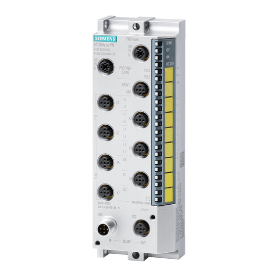
Product overview What is the ET 200eco distributed I/O station? Definition The ET 200eco distributed I/O station is a compact DP slave (degree of protection IP 65, IP 66 or IP 67). Field of application • Due to its rugged design and degree of protection IP 65, IP 66 or IP 67, the ET 200eco distributed I/O station is primarily suitable for operation under harsh industrial conditions. -
Page 17: Terminal Block
Product overview ET200eco components The table provides an overview of the major components of ET 200eco: Table 1-1 ET 200eco components Component Function Figure I/O module You connect sensors and actuators to the I/O module. The I/O module is available in the following versions: •... - Page 18 Product overview ET 200eco Distributed I/O Station A5E00158716-02...
-
Page 19: Installation
Installation Easy installation The design of the ET 200eco distributed I/O station allows easy installation. Chapter overview Chapter Topic Page Mounting position/dimensions I/O module installation Installation of the terminal block Label replacement Removing ET 200eco Setting the PROFIBUS address Mounting position/dimensions Mounting position The ET 200eco can be mounted in any position Mounting and spacing dimensions... -
Page 20: I/O Module Installation
Installation I/O module installation Properties • The I/O module must be mounted onto a solid base. • The I/O module (without terminal block) can be prewired. Requirements Screws: Screw type Explanation M5 cylindrical head screw to ISO Minimum screw length: 20 mm. 1207/ISO 1580 (DIN 84/DIN 85) Additionally required: DIN 125 washers. -
Page 21: Installation Of The Terminal Block
Installation Procedure Using the screws, tighten the I/O module onto a level base. The I/O module must be screwed onto the base at both fastening points (at the front panel top and bottom). Tightening torque: 3 N/m. 5.5 x 7 Figure 2-1 Mounting the I/O module onto the base Installation of the terminal block... -
Page 22: Label Replacement
Installation Installation of the terminal block 1. Insert the terminal block into the I/O module. 2. Bolt the terminal block to the I/O module (with a torque of 1 to 1.3 nm). Tighten the screws evenly in diagonally opposite sequence. The terminal block is equipped with four captive screws (see Figure 2-2). -
Page 23: Removing Et 200Eco
Installation Tools required Screwdriver, 2.5 mm to 4 mm blade Label replacement 1. Insert the screwdriver into the small opening on the label and lever it out. Figure 2-3 Removing labels 2. Snap the new label tag into the holder on the module. Removing ET 200eco Procedure The ET 200eco is wired and in operation. -
Page 24: Profibus Address Assignment
Installation PROFIBUS address assignment Properties Specify the PROFIBUS address under which the ET 200eco I/O station is accessed on PROFIBUS DP. Requirements • The PROFIBUS-DP address for ET 200eco is set at the terminal block. • All PROFIBUS-DP addresses must be unique. •... -
Page 25: How To Set The Profibus-Dp Address At Terminal Block M12, 7/8
Installation How to set the PROFIBUS-DP address at the terminal block M12, 7/8” The permitted PROFIBUS-DP address range is 1 to 99. 1. Remove both lock caps on the rotary selector switches (use the 14–mm socket wrench if need be). 2. -
Page 26: How To Unscrew The Configuration Module
Installation How to set the PROFIBUS-DP address at the ECOFAST terminal block Valid range of the PROFIBUS DP addresses: 1 to 99. If you select a higher address, the I/O module will return an error signal via the red bus error LED. 1. -
Page 27: Wiring
Wiring Introduction Special rules and regulations apply to the integration of ET 200eco distributed I/O stations in plants and systems. This chapter provides an overview of the essential rules for the integration of ET 200eco distributed I/O stations in plants or systems. Chapter overview Chapter Topic... -
Page 28: Et 200Eco Operation On A Grounded Power Supply
Wiring Plant startup after specific events The table below shows what you need to observe for a restart of the plant after specific events. If... then... Startup after voltage drop or loss hazardous states must not develop. If necessary, force EMERGENCY–OFF! Startup of ET 200eco after an interrupt of bus communication Startup after release of the... - Page 29 Wiring Definition: Grounded powersupply The neutral conductor of grounded power supplies is connected to ground. Any ground fault at a live conductor or grounded part of the system will trigger a response of the protection devices. Components and protective measures Vario1us components and protective devices are mandatory for plant/system installation.
-
Page 30: Electrical Structure Of The Et 200Eco System
Wiring Overall structure of ET 200eco Figure 3-1 shows the overall structure of an ET 200eco distributed I/O station ((Load supply voltages and grounding concept) with power supply from a TN-S network. Low–voltage distribution, e.g. in a TN-S system (3 400 V) ET 200eco Terminal block... -
Page 31: Potentials In An Et 200Eco Installation With M12, 7/8" Terminal Block
Wiring ET 200eco structure The figures below show the potentials in an ET 200eco installation with M12, 7/8” terminal block. terminal block I/O module M12, 7/8” RS485 interface Data Power supply P5V2 M5V2 Short-cir– cuit pro– 24 VDC 1 L+ tection 24 VDC 2 L+... -
Page 32: Terminal Block
Wiring terminal block I/O module ECOFAST RS485 interface Data Power supply Short–cir– cuit pro– 24 VDC 1 L+ tection 24 VDC 2 L+ Through loop 1 L+ 2 L+ 24 VDC Grounding bus * Only for I/O module 8 DI / 8 DO 2 A Figure 3-3 Potentials in an ET 200eco installation with ECOFAST terminal block Note... -
Page 33: Wiring Et 200Eco
Wiring Note The following applies to an ET 200eco with terminal block: • The electronic/sensor power supply 1L+ powers the sensors. • The outputs are powered via by the load voltage supply 2L+. Protecting components from damage In order to avoid the destruction of ET200eco components, you must always provide external line fusing for the electronic/sensor power supply and load voltage: •... -
Page 34: How To Connect Et 200Eco To Protective Earth (Pe)
Wiring 3.4.1 How to connect ET 200eco to protective earth (PE) Properties • You must always connect the ET 200eco to protective earth. The I/O module is equipped with a grounding bolt for this purpose. • The connection to protective earth is also required for the discharge of electrical interference to ground and for EMC compatibility. -
Page 35: Connecting The I/O Module To Protective Earth
Wiring How to connect ET 200eco to protective earth 1. Strip the grounding cable and crimp on the cable lug. 2. Screw the cable lug onto the M5 bolt of the I/O module. Tightening torque: 3 N/m. Figure 3-4 Connecting the I/O module to protective earth 3.4.2 How to wire I/O modules Properties... -
Page 36: Pin Assignment Of The M12 Coupler Plug For The I/O Module 8 Di
Wiring Accessories required • prefabricated cable with 5–pin M12 coupler plug • or 3-, 4- or 5–conductor flexible copper cable (conductor cross–section must be: v 0.75 mm and a 5–pin M12 coupler plug (see Tables 3-1, 3-2, 3-3 and 3-6). •... -
Page 37: Pin Assignment For M12 Coupler Plug For I/O Module 8 Do 2 A
Wiring • I/O module 8 DO 2 A Table 3-3 Pin Assignment for M12 Coupler Plug for I/O Module 8 DO 2 A Assignment X1 to X8 View of the coupler plug (wiring side) n.c. 3- or n.c. 4–pole cable 4–pole cable Ground potential, load voltage supply (2M) -
Page 38: Pin Assignment Of M12 Coupler Plug For I/O Module
Wiring • I/O module 8 DI / 8 DO 2 A Table 3-5 Pin assignment of M12 coupler plug for I/O module 8 DI / 8 DO 2 A Assignment View of the coupler plug (wiring side) 24V sensor power supply (1L+)* 4- or 5–pole copper cable Input signal Ground potential, sensor/load voltage... - Page 39 Wiring • I/O module 8 DI / 8 DO 1.3 A Table 3-6 Pin assignment of M12 coupler plug for I/O module 8 DI / 8 DO 1.3 A Assignment X1, X3, X5, X7 View of the coupler plug (wiring side) 24V sensor power supply (1L+)* 4- or 5–pole copper cable Input signal** (n+1)
-
Page 40: How To Connect The M12 Plug
Wiring How to connect the M12 plug 1. Insert the plug into the corresponding round socket on the I/O module. Ensure that the plug and socket interlock (slot and groove). 2. Tighten the knurled screw of the plug. Figure 3-5 How to connect the M12 plug ET 200eco Distributed I/O Station 3-14... -
Page 41: Y Connector
Wiring How to connect the Y connector The Y connector can be used to connect two actuators or sensors to the inputs/outputs of the ET 200eco. We recommend the use of this Y connector for configurations in which two channels are assigned per module socket: •... -
Page 42: Y Connector For I/O Module 16 Do 0.5 A
Wiring Pin assignment for the Y connector of I/O module 16 DI Table 3-7 The Y connector and I/O module 16 DI Assignment for coupler plug X1 to X8 Layout A (top) B (lower) Y connector 24V sensor power supply (1L+)* A (top) n.c. -
Page 43: Di / 8 Do 2 A
Wiring Pin assignment for the Y connector of I/O module 8 DI / 8 DO 2 A Table 3-9 Y connector plug for I/O module 8 DI / 8 DO 2 A Assignment for coupler plug X1 to X8 Layout A (top) B (lower) Y connector... -
Page 44: Di / 8 Do 1.3 A
Wiring Pin assignment for the Y connector of I/O module 8 DI / 8 DO 1.3 A Table 3-10 Y connector plug for I/O module 8 DI / 8 DO 1.3 A Assignment of coupler plug X1, X3, X5, Layout A (top) B (lower) Y connector... -
Page 45: How To Wire The Ecofast Terminal Block
Wiring 3.4.3 How to wire the ECOFAST terminal block Properties • Connect the supply voltages and PROFIBUS DP to the ECOFAST terminal block via ECOFAST connector. • You can loop the supply voltages and PROFIBUS DP through an additional ECOFAST connector. •... -
Page 46: Pin Assignment Of The Ecofast Connector
Wiring How to wire the ECOFAST connector Table 3-11 shows you the pin assignment of the ECOFAST connector Table 3-11 Pin assignment of the ECOFAST connector Assignment View of the ECOFAST connector (terminal side for incoming signals and loop–through) PROFIBUS DP Signal A Signal A Signal B PROFIBUS DP Signal B... -
Page 47: Connecting The Ecofast Connector
Wiring How to connect the ECOFAST connector 1. Push down the interlocking mechanism for the ECOFAST connector. 2. Insert the ECOFAST connectors (for 1L+, 2L+ and PROFIBUS DP) into the sockets of the terminal block. Note the mechanical encoding of the connectors for incoming signals and loop–through. -
Page 48: Connecting The Ecofast Connector
Wiring How to install the PROFIBUS DP terminating resistor The first and the last node of a PROFIBUS DP segment must be terminated with a wave impedance. At the last bus node, plug the terminal resistor module onto the right–side connector of the corresponding ECOFAST terminal block. -
Page 49: Wiring The M12, 7/8" Terminal Block
Wiring 3.4.4 Wiring the M12, 7/8” terminal block Properties • Connect the power supplies and PROFIBUS DP to the M12, 7/8” terminal block: – M12 terminals: PROFIBUS DP – 7/8” terminals: Power bus • You can loop the power supplies and PROFIBUS DP through the M12 or 7/8” round sockets. -
Page 50: Pin Assignment Of The M12 Plug (Profibus Dp)
Wiring How to wire the M12, 7/8” plug Table 3-12 or 3-13 shows you the pin assignment of the M12, 7/8” plug: Table 3-12 Pin assignment of the M12 plug (PROFIBUS DP) Assignment View of the M12 plug (wiring side) Power supply + (P5V2) Supply DP1 Signal A (green) -
Page 51: How To Wire The M12, 7/8" Plug
Wiring Note We recommend you wire the power supply with the cables specified in Appendix A (order no.) ( 5x1.5 mm with 7/8” connectors). If you want to produce a self–made cable, we recommend you use a conductor cross–section of 1.5 mm How to wire the M12, 7/8”... -
Page 52: How To Connect The M12 Terminating Resistor
Wiring M12 How to install the PROFIBUS DP terminating resistor The first and the last node of a PROFIBUS DP segment must be terminated with a wave impedance. Always terminate the PROFIBUS DP with an M12 terminating resistor if the ET 200eco is the last PROFIBUS node. -
Page 53: Loop-Through Of The Profibus Dp And Power Bus
Wiring 3.4.5 How to loop the PROFIBUS DP and the supply voltage Properties The terminal block is equipped with one plug for the power bus, one socket for looping the power bus and one socket for PROFIBUS-DP. The power bus connector and the loop–through socket are interconnected internally. - Page 54 Wiring Caution If you ignore the stipulated maximum power supply currents and required conductor cross–sections, you may cause excessive heating of the cable insulation and contact and damage to your equipment. ET 200eco Distributed I/O Station 3-28 A5E00158716-02...
-
Page 55: Commissioning And Diagnostics
Commissioning and diagnostics Chapter overview Chapter Topic Page ET 200eco configuration ET 200eco commissioning and startup Diagnostics with LED display Diagnostics with STEP 5 and STEP 7 ET 200eco Distributed I/O Station A5E00158716-02... -
Page 56: Gsd File Implementation In The Configuration Software
Configure the ET 200eco distributed I/O station via the GSD file. In this GSD file, the ET 200eco is implemented as standard slave in your system. You can download the GSD files • under the Internet URL http//www.ad.siemens.de/csi_e/gsd GSD filenames for ET 200eco: • I/O module 8 DI: Siem80db.gs* •... -
Page 57: Software Required For Commissioning
Commissioning and diagnostics ET 200eco commissioning and startup Software requirements Table 4-2 Software required for commissioning Configuration Version Notes software used STEP 7 V4.02 or higher You have implemented the GSD file for ET 200eco in STEP 7. V 5.1 or higher; The GSD file is included in the scope of delivery. - Page 58 Commissioning and diagnostics ET 200eco startup Switch on 1L+ and, if required, 2L+ for ET 200eco The LEDs “ON”,“24 VDC” and “BF” are lit* ET 200eco sets the outputs to “0” state and applies the set PROFIBUS address ET 200eco receives configur– ation data from the DP master Are the SF is lit red...
-
Page 59: Led Display On The Et 200Eco
Commissioning and diagnostics Diagnostics with LED display I/O module Status display per channel (green) BF ON 24 VDC Load voltage supply 2L+ (green) (no LED on I/O module 8 DI and I/O module 16 DI) Electronic/sensor power supply 1L+ (green) Bus error (red) Group error (red) Figure 4-2... -
Page 60: Status And Error Display With Leds
Commissioning and diagnostics Table 4-5 Status and error display with LEDs LEDs Meaning Remedy • DP slave is in startup mode. – • • Communication to the DP master is Check the PROFIBUS DP down. connection. • • The DP slave does not recognize Check the DP master. - Page 61 Commissioning and diagnostics Status display 24 VDC The 24 VDC LED is lit green after you have connected the load voltage supply 2L+. This LED is only available for I/O module 8 DO 2 A, 8 DI / 8 DO 2 A and I/O module 8 DI / 8 DO-2 1.3 A.
-
Page 62: Reading Diagnostics Data Of Et 200Eco Under Step 7 And Step 5
FB 125/FC 125 Slave diagnostics Download FB/FC 125 evaluation under the Internet URL: http://www.ad.siemens.de/ simatic-cs, product ID = 387 257 SIMATIC S5 with FB 192 “IM308C” Fetching diagnostics data For installation information IM 308-C as DP... - Page 63 Commissioning and diagnostics Example of how to fetch slave diagnostics data with SFC 13 “DPNRM_DG” This example shows you how to use SFC 13 to view diagnostics data of a DP slave in the STEP 7 user program. Assumptions For this STEP 7 user program we shall assume that: •...
- Page 64 Commissioning and diagnostics Example of how to use FB 192 “IM308C” to read slave diagnostic data This example shows you how to use SFC 192 to view diagnostics data of a DP slave in the STEP 5 user program. Assumptions For this STEP 5 user program we shall assume that: •...
-
Page 65: Structure Of Et 200Eco Slave Diagnostics Data
Commissioning and diagnostics 4.4.2 Structure of ET 200eco slave diagnostics Structure of ET 200eco slave diagnostic data Byte 0 Byte 1 Station status 1 to 3 Byte 2 Byte 3 Master PROFIBUS address High byte Byte 4 Manufacturer ID Byte 5 Low byte (see Table 4-10) Byte 6... -
Page 66: Structure Of The Station Status 1(Byte 0) Et 200Eco
Commissioning and diagnostics 4.4.3 Station status 1 to 3 Definition Station status 1 to 3 provides an overview of the status of a DP slave. Station status 1 Table 4-7 Structure of the station status 1(byte 0) ET 200eco Meaning Cause / Remedy •... -
Page 67: Structure Of Station Status 2 (Byte 1) Et 200Eco
Commissioning and diagnostics Station status 2 Table 4-8 Structure of station status 2 (byte 1) ET 200eco Meaning 1: The DP slave must be reconfigured. 1: A diagnostic message is queued. The DP slave will not operate unless the error is eliminated (static diagnostic message). 1: The bit is always ”1”... -
Page 68: Structure Of The Et 200Eco Manufacturer Id (Bytes 4 And 5)
Commissioning and diagnostics 4.4.4 Master PROFIBUS address Definition Diagnostic byte 3 contains the PROFIBUS address of the master that: • assigned the parameters to the DP slave and • has read and write access to the DP slave. in byte 3 The master PROFIBUS address value FF in byte 3 indicates that the DP master has not assigned parameters to the DP slave. -
Page 69: Structure Of Et 200Eco Device-Specific Diagnostics Data
Commissioning and diagnostics 4.4.6 Device–specific diagnostic data Definition Device–specific diagnostic data allows you to recognize a short–circuit at the electronic/sensor power supply (1L+) or missing load voltage supply (2L+). The header contains information on the length of device–specific diagnostic data. Device–specific diagnostic data Structure of device–specific diagnostic data for ET 200eco: Bit no. - Page 70 Commissioning and diagnostics ET 200eco Distributed I/O Station 4-16 A5E00158716-02...
-
Page 71: General Technical Data
General technical data What are general technical data? These general technical data contain the standards and test values the ET200eco distributed I/O station is compliant with, or the criteria for testing the ET 200eco distributed I/O station. Chapter overview Chapter Topic Page Standards and approvals... -
Page 72: General Technical Data
• 89/336/EEC ”EMC compatibility” (EMC guideline) • 73/23/EEC ”Electrical equipment designed for operation within specific voltage limits” (Low–voltage guideline EU Declarations of Conformity are kept available for relevant authorities at: Siemens Corporation, Automation and Drives A & D AS RD 4, PO Box 1963... -
Page 73: Emc Compatibility, Shipping And Storage Conditions
General technical data EMC compatibility, shipping and storage conditions Definition EMC compatibility refers to the ability of electrical equipment to operate efficiently in an electromagnetic environment, without emission of electromagnetic disturbance. The ET 200eco distributed I/O station is also compliant with EMC legislation of the European common market. - Page 74 General technical data Sinusoidal disturbance variables The table below shows the EMC compatibility of the ET 200eco distributed I/O station in relation to sinusoidal disturbances. RF coupling toIEC 6100043 RF coupling to Electromagnetic RF field IEC 61000 amplitude–modulated pulse–modulated 900 MHz "5 MHz 80 to 1000 MHz 0.15 to 80 MHz 10 V/m...
-
Page 75: Mechanical And Climatic Ambient Conditions
General technical data Mechanical and climatic ambient conditions Climatic ambient conditions The following climatic ambient conditions apply: Ambient conditions Fields of application Remarks 0 to 55 _C Temperature range all mounting positions Temperature change 10 K/h Relative humidity 15 to max. 95 % without condensation Atmospheric pressure 1080 to 795 hPa... - Page 76 General technical data Tests for determining mechanical ambient conditions The table below provides information on the type and scope of the tests for mechanical ambient conditions. Test object Testing stan- terminal blocks and electronic modules dard Vibration Vibration test ac- Type of oscillation: Frequency test cycles at a rate of change of 1 oc- cording to tave/minute.
-
Page 77: Specification Of Isolation Tests, Protection Class
General technical data Specification of isolation tests, protection class, type of protection and rated voltage for ET 200eco Test voltage The dielectric strength is verified during routine testing using the following test voltages according to IEC 61131-2: Circuits with a rated voltage of U against Test voltage other circuits or ground... - Page 78 General technical data Rated operating voltage The table below shows the rated voltage and corresponding tolerances for the operation of the ET 200eco distributed I/O station. Rated voltage Tolerance range 24 VDC 20.4 to 28.8 VDC Note Trouble–free operation of the terminating resistor is only ensured if it is connected to an electronic/sensor power supply (1L+) with a tolerance of range of ±10%.
- Page 79 Technical data The ET 200eco system consists of various components. In this chapter you will find the technical data of those components. Chapter overview Chapter Topic Page ECOFAST terminal block (6ES7 194-3AA00-0AA0) Terminal block M12, 7/8” (6ES7 194-3AA00-0BA0) I/O module 8 DI (6ES7 141-3BF00-0XA0) I/O module 16 DI (6ES7 141-3BH00-0XA0) 6-10 I/O module 8 DO 2A (6ES7 142-3BF00-0XA0)
-
Page 80: Technical Data
Technical data ECOFAST terminal block (6ES7 194-3AA00-0AA0) Properties Characteristics of the ECOFAST terminal block: • Can be plugged in and screwed on to any I/O module. • Connection to power supplies and PROFIBUS DP via ECOFAST connector (at socket X01, supply lines). •... -
Page 81: Block Diagram Of The Ecofast Terminal Block
Technical data Block diagram The figure below shows the ECOFAST terminal block. PROFIBUS address 1 L+ 1 L+ ECOFAST connector 2 L+ 2 L+ Figure 6-1 Block diagram of the ECOFAST terminal block Technical data Dimensions and weight Power loss Dimensions Power loss of the module typically 2 W... -
Page 82: Terminal Block M12, 7/8" (6Es7 194-3Aa00-0Ba0)
Technical data Terminal block M12, 7/8” (6ES7 194-3AA00-0BA0) Properties Characteristics of the M12, 7/8” terminal block: • Can be plugged in and screwed on to any I/O module. • Connection of – PROFIBUS DP via M12 connector (at infeed socket DP1) –... -
Page 83: Pin-Out Of The Plugs Dp1 And Dp2 (M12)
Technical data Pin assignment of the M12-, 7/8” sockets The table below shows the pin assignment of the two M12, 7/8” sockets for the connection to the power supplies and PROFIBUS DP. Table 6-2 Pin-out of the plugs DP1 and DP2 (M12) Assignment of the M12 sockets DP1 View of the plug (infeed) and DP2 (loop–through) -
Page 84: Block Diagram Of The M12, 7/8" Terminal Module
Technical data Block diagram The figure below shows the M12, 7/8” terminal block. PROFIBUS address 1 L+ P5V2 M5V2 Shielding Figure 6-2 Block diagram of the M12, 7/8” terminal module Technical dataterminal block”# Dimensions and weight Power loss Dimensions Power loss of the module typically 2 W D (mm) Power loss depends on the feed–through current... -
Page 85: Pin-Out Of The Digital Input Sockets X1 To X8
Technical data I/O module 8 DI (6ES7 141-3BF00-0XA0) Properties Characteristics of the I/O module 8 DI: • 8 digital inputs • Input nominal voltage DC 24 V • suitable for switches and proximity switches (BEROs) Pin assignment of the DI sockets The table below shows the pin assignment of the eight digital input sockets. -
Page 86: Block Diagram Of I/O Module 8 Di
Technical data Block diagram The figure below shows the block diagram of I/O module 8 DI. RS485 in- terface internal power Electronic Short–circuit pro- tection Status Socket terminals (see Table Figure 6-3 Block diagram of I/O module 8 DI ET 200eco Distributed I/O Station A5E00158716-02... - Page 87 Technical data Technical data of I/O module 8 DI Dimensions and weight Status, interrupts, diagnostics Dimensions Status display Green LED per D (mm) channel Weight approx. 210 g Interrupts Module–specific data Diagnostic functions • Transmission rates 9.6/19.2/45.45/93.75/ Group error display Red LED (SF) 187.5/500 kbps •...
-
Page 88: Pin-Out Of The Digital Input Sockets X1 To X8
Technical data I/O module 16 DI (6ES7 141-3BH00-0XA0) Properties Characteristics of I/O module 16 DI: • 16 digital inputs • Input nominal voltage DC 24 V • suitable for switches and proximity switches (BEROs) Pin assignment of the DI sockets The table below shows the pin assignment of the eight digital input sockets. -
Page 89: Block Diagram Of I/O Module 16 Di
Technical data Block diagram The figure below shows the block diagram of I/O module 16 DI. RS485 in- terface Electronic internal power Short–circuit pro- tection Status Socket terminals (see Table Figure 6-4 Block diagram of I/O module 16 DI ET 200eco Distributed I/O Station 6-11 A5E00158716-02... - Page 90 Technical data Technical data of I/O module 16 DI Dimensions and weight Status, interrupts, diagnostics Dimensions Status display Green LED per D (mm) channel Weight approx. 210 g Interrupts Module–specific data Diagnostic functions • Transmission rates 9.6/19.2/45.45/93.75/ Group error display Red LED (SF) 187.5/500 kbps •...
-
Page 91: Pin-Out Of The Digital Output Sockets X1 To X8
Technical data I/O module 8 DO 2A (6ES7 142-3BF00-0XA0) Properties The I/O module 8 DO 2A has the following features: • 8 digital outputs • output current = 2 A per output • rated load voltage = 24 VDC • suitable for magnetic solenoid valves, DC contactors and signal lamps Pin assignment of the DO sockets The table below shows the pin assignment of the eight digital output sockets. -
Page 92: Block Diagram Of I/O Module 8 Do 2A
Technical data Block diagram The following figure shows the block diagram of the I/O module 8 DO 2A. internal power Electronic RS485 in- terface 24 VDC Load voltage monitoring Short–circuit protection Status Socket terminals (see Table X1, X2 ..X8 Figure 6-5 Block diagram of I/O module 8 DO 2A ET 200eco Distributed I/O Station... - Page 93 Technical data Technical data of I/O Module 8 DO 2A Dimensions and weight Status, interrupts, diagnostics Dimensions Status display Green LED per D (mm) channel Weight approx. 210 g Interrupts Module–specific data Diagnostic functions • Transmission rates 9.6/19.2/45.45/93.75/ Group error display Red LED (SF) 187.5/500 kbps •...
-
Page 94: Pin-Out Of The Digital Output Sockets X1 To X8
Technical data I/O module 16 DO 0.5 A (6ES7 142-3BH00-0XA0) Properties The I/O module 16 DO 0.5 A has the followng features: • 16 digital outputs • output current = 0,5 A per output • rated load voltage = 24 VDC •... -
Page 95: Block Diagram Of I/O Module 16 Do 0.5 A
Technical data Block diagram The following figure shows the block diagram of the I/O module 16 DO 0.5 A. internal power Electronic RS485 in- terface 24 VDC Load voltage monitoring Short–circuit protection Status Socket terminals (see Table X1, X2 ..X8 Figure 6-6 Block diagram of I/O module 16 DO 0.5 A ET 200eco Distributed I/O Station... - Page 96 Technical data Technical Data of I/O Module 16 DO 0.5 A Dimensions and weight Status, interrupts, diagnostics Dimensions Status display Green LED per D (mm) channel Weight approx. 210 g Interrupts Module–specific data Diagnostic functions • Transmission rates 9.6/19.2/45.45/93.75/ Group error display Red LED (SF) 187.5/500 kbps •...
-
Page 97: Pin-Out Of The Digital Input And Output Sockets X1 To X8
Technical data I/O module 8 DI / 8 DO 2 A (6ES7 143-3BH00-0XA0) Properties The I/O module 8 DI / 8 DO 2 A has the following features: • 8 digital inputs • Input nominal voltage DC 24 V • suitable for switches and proximity switches (BEROs) •... -
Page 98: Block Diagram Of I/O Module 8 Di / 8 Do 2A
Technical data Block Diagram The following figure depicts the block diagram of the I/O module 8 DI / 8 DO 2A. RS485 in- terface internal power Electronic Short–circuit pro- tection 24 VDC Load voltage Status monitoring Short–circuit protection Status Socket terminals (see Table . - Page 99 Technical data Technical Data of the I/O Module 8 DI / 8 DO 2A Dimensions and weight Current load • on power supply 1L+ typically 70 mA Dimensions • D (mm) on load voltage supply typically 60 mA Weight approx. 210 g Power loss of the module typically 5 W Module–specific data...
-
Page 100: I/O Module 8 Di / 8 Do 1.3 A (6Es7 143-3Bh00-0Xa0)
Technical data • Actuator selection data for power increase Output voltage Digital input control possible • at signal 1 min. 2L+ (– 0.8 V) Switching frequency • Output current resistive load max. 100 Hz • • at signal 1 inductive load max. - Page 101 Technical data Table 6-9 Pin-out of the digital input and output sockets X1 to X8 Assignment of Assignment of Assignment of Assignment of View of the socket X1 socket X2 socket X3 socket X4 socket (Front view) 24 V sensor n.c.
-
Page 102: Block Diagram Of I/O Module 8 Di / 8 Do 1.3 A
Technical data Block Diagram The following figure shows the block diagram of the I/O module 8 DI / 8 DO 1.3 A. RS485 in- terface internal power Electronic Short–circuit pro- tection 24 VDC Load voltage Status monitoring Short–circuit protection Status Socket terminals (see Table X4 X6 X8... - Page 103 Technical data Technical Data of the I/O Module 8 DI / 8 DO 1.3 A Dimensions and weight Isolation test voltage 500 VDC Dimensions Current load • D (mm) on power supply 1L+ typically 70 mA • Weight approx. 210 g on load voltage supply typically 60 mA Module–specific data...
- Page 104 Technical data • Actuator selection data for power increase Output voltage Digital input control possible • at signal 1 min. 2L+ (– 1.2 V) Switching frequency • Output current resistive load max. 100 Hz • • at signal 1 inductive load max.
-
Page 105: Order Numbers
Order numbers Introduction Find below the order numbers of all components you may require for operating the ET 200eco. ET 200eco components Table A-1 ET 200eco components – Order numbers Description Order no. I/O module 8 DI 6ES7 141-3BF00-0XA0 I/O module 16 DI 6ES7 141-3BH00-0XA0 I/O module 8 DO 2 A 6ES7 142-3BF00-0XA0... -
Page 106: I/O Module Accessories - Order Numbers
Order numbers I/O module accessories Table A-3 I/O module accessories – Order numbers Description Order no. M12 caps 3RX9 802-0AA00 Y connector M12, 5–pin (for dual connection of actuators 6ES7 194-1KA01-0XA0 and sensors to digital inputs/outputs. Angled coupler plug M12, 5–pin (for connecting actuators or on request sensors;... -
Page 107: M12, 7/8" Terminal Block Accessories - Order Numbers
Order numbers Table A-4 Accessories for the ECOFAST terminal block – Order numbers, continued Description Order no. • ECOFAST hybrid cable sections (2 and 2x2 copper conductors) of various lengths: 20 m 6XV1 830-7AN20 50 m 6XV1 830-7AN50 100 m 6XV1 830-7AT10 •... -
Page 108: Step 7 And Simatic S7 Manual
Manual containing an ISBN 3-89578-123-1 easy introduction to – Installation, configuration and use of PROFIBUS DP and PROFIBUS DP under SIMATIC S7 – At your local SIEMENS implementation of branch location: Josef Weigmann, Gerhard Kilian automation tasks with A19100-L531-B772 Publicis MCD Verlag, 2nd edition,... -
Page 109: Dimensional Drawings
Dimensional drawings Introduction Find below the dimensional drawings of the major components for ET 200eco. I/O module with installed M12, 7/8” terminal block 42,1 53,9 Figure B-1 Dimensional drawing of an I/O module with installed M12, 7/8” terminal block ET 200eco Distributed I/O Station A5E00158716-02... -
Page 110: Dimensional Drawing Of An I/O Module With Installed Ecofast
Dimensional drawings I/O module with installed ECOFAST terminal block 38,5 59,85 Figure B-2 Dimensional drawing of an I/O module with installed ECOFAST terminal block ET 200eco Distributed I/O Station A5E00158716-02... -
Page 111: I/O Address Area
I/O address area I/O module 8 DI Assignment of the module inputs in the process image: Input byte x Input signal X1 at pin 4 Input signal X2 at pin 4 Input signal X3 at pin 4 Input signal X4 at pin 4 Input signal X5 at pin 4 Input signal X6 at pin 4 Input signal X7 at pin 4... -
Page 112: Address Space Of I/O Module 16 Di
I/O address area I/O module 16 DI Assignment of the module inputs in the process image: Input byte x Input signal X1 at pin 4 Input signal X2 at pin 4 Input signal X3 at pin 4 Input signal X4 at pin 4 Input signal X5 at pin 4 Input signal X6 at pin 4 Input signal X7 at pin 4... -
Page 113: Address Area Of I/O Module 16 Do 0.5 A
I/O address area I/O module 16 DO 0.5 A Assignment of module outputs in the process image table: Output byte x Output signal X1 at pin 4 Output signal X2 at pin 4 Output signal X3 at pin 4 Output signal X4 at pin 4 Output signal X5 at pin 4 Output signal X6 at pin 4 Output signal X7 at pin 4... - Page 114 I/O address area I/O module 8 DI / 8 DO 2 A Assignment of module inputs/outputs in the process image table: Input byte x Input signal X1 at pin 2 Input signal X2 at pin 2 Input signal X3 at pin 2 Input signal X4 at pin 2 Input signal X5 at pin 2 Input signal X6 at pin 2...
- Page 115 I/O address area I/O module 8 DI / 8 DO 1.3 A Assignment of module inputs/outputs in the process image table: Input byte x Input signal X1 at pin 4 Input signal X1 at pin 2 Input signal X3 at pin 4 Input signal X3 at pin 2 Input signal X5 at pin 4 Input signal X5 at pin 2...
- Page 116 I/O address area ET 200eco Distributed I/O Station A5E00158716-02...
-
Page 117: Glossary
• ET 200M, ET 200S, ET 200X, ET 200L, ET 200eco • DP/AS–I Link • S5-95U with PROFIBUS DP slave interface • other DP slaves made by SIEMENS or third parties Distributed I/Os are interconnected to the DP master via PROFIBUS DP. DP Address →... - Page 118 Glossary DP master A ³master that operates in accordance with IEC 61784-1:2002 Ed1 CP 3/1 is referred to as a DP master. DP-Norm The DP standard is the bus protocol of the ET 200S distributed I/O system in accordance with IEC 61784-1:2002 Ed1 CP 3/1. DP slave A ³...
- Page 119 Glossary Grounding The term refers to the grounding of electrically conductive components a metallic conductor. I/O module Sensors and actuators are connected to the I/O module via coupler plug or Y connector. Master who are in possession of the token may send data to other nodes and also request data from other nodes (= active node).
- Page 120 Glossary PROFIBUS address All bus nodes must be assigned a unique PROFIBUS address for their identification on the PROFIBUS network. Available PROFIBUS addresses for ET 200eco: 1 to 99. PUR sheath Cable with polyurethane (PUR) sheath (protective sheath). Reference potential Arbitrary electrical point of reference (zero potential) for the measurement and/or monitoring of voltages in circuits referenced to this potential.
- Page 121 Index Numbers Distributed I/O system ET 200eco definition, 1-4, 1-5 24 VDC power supply, 3-2 field of application, 1-4 view, 1-4 Distributed I/O systems-field of application, 1-2 Disturbance spikes, 5-3 Automation system, Glossary-1 Double connection, of actuators/sensors, 3-15 DP-address, Glossary-1 DP-master, 1-2, Glossary-2 DP-slave, 1-2, Glossary-2 DP-standard, Glossary-2...
- Page 122 Index General rules, 3-1 M12 plug, connecting, 3-14 General technical data, 5-1 M12, 7/8 terminal block, wiring, 3-23 Ground, Glossary-2 Manual, purpose, iii Grounded power supply, 3-3 Manufacturer ID, structure, 4-14 GSD file, 4-2 Master, Glossary-3 Guide, for this manual, iv Master-PROFIBUS-address, structure, 4-14 Mechanical ambient conditions, 5-5 Mounting dimensions, 2-1...
- Page 123 Index Shipping conditions, 5-3 Temperature, 5-4 Sinusoidal disturbance variables, 5-4 Terminating resistor, 3-22, 3-26 Slave, Glossary-4 Test voltage, 5-7 Slave diagnostics, 4-8 TN-S network, 3-4 structure of extended diagnostic data, 4-11 Software-requirements, 4-3 Standard EN 50170, volume 2, PROFIBUS, Vibration, 5-6 Standards and approvals, 5-2 Startup, 4-3 Station ID, Glossary-4...
-
Page 124: Index
Index ET 200eco Distributed I/O Station Index-4 A5E00158716-02...
Need help?
Do you have a question about the SIMATIC ET 200eco and is the answer not in the manual?
Questions and answers