Table of Contents
Advertisement
Quick Links
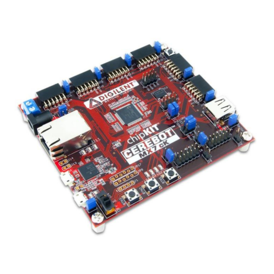
chipKIT™ Pro MX7 Board Reference Manual
Revised April 15, 2016
This manual applies to the chipKIT Pro MX7 rev. B and C
Overview
chipKIT Pro MX7is the new name for Cerebot MX7. This board retains all functionality of the Cerebot MX7.
The chipKIT Pro MX7 is a microcontroller development board based on the Microchip® PIC32MX795F512L, a
member of the 32-bit PIC32 microcontroller family. It is compatible with Digilent's line of peripheral modules,
Pmod™, and is suitable for use with the Microchip MPLAB
use with the chipKIT™ MPIDE development environment. chipKIT MPIDE is a PIC32-based system compatible with
many existing Arduino® code examples, reference materials, and other resources.
The chipKIT Pro MX7 is designed to be easy to use and suitable for use by anyone from beginners to advanced
users experimenting with embedded control and network communications application. A built-in
programming/debugging circuit compatible with the Microchip MPLAB IDE is provided, so no additional hardware
is required for use with MPLAB. The kit contains everything needed to start developing embedded applications
using either the MPLAB IDE or the MPIDE.
The chipKIT Pro MX7 provides 52 I/O pins that support a number of peripheral functions, such as UART, SPI, I
ports, as well as five pulse-width modulated outputs and five external interrupt inputs. Its network and
communications features also include a 10/100 Ethernet interface, Full Speed USB 2.0 OTG interface, and dual CAN
network interfaces. Ten of the I/O pins can be used as analog inputs in addition to their use as digital inputs and
outputs.
The chipKIT Pro MX7 can be powered in various ways via USB, or using an external AC-DC power adapter.
chipKIT Pro MX7 board.
DOC#: 502-296
Other product and company names mentioned may be trademarks of their respective owners.
®
IDE tools. The chipKIT Pro MX7 is also compatible for
Features of the chipKIT Pro MX7 include:
PIC32MX795F512L microcontroller
Support for programming and debugging within the
Microchip MPLAB development environment
Support for programming within the chipKIT MPIDE
development environment
Six Pmod ports for Digilent peripheral module
boards
10/100 Ethernet
USB 2.0 compatible Device, Host, and OTG support
Two CAN network interfaces
Three push buttons
Four LEDs
Multiple power supply options, including USB
powered
ESD protection and short circuit protection for all
I/O pins.
Copyright Digilent, Inc. All rights reserved.
1300 Henley Court
Pullman, WA 99163
509.334.6306
www.digilentinc.com
2
C™
Page 1 of 35
Advertisement
Table of Contents

Related Manuals for Digilent chipKIT Pro MX7


Summary of Contents for Digilent chipKIT Pro MX7
- Page 1 Arduino® code examples, reference materials, and other resources. The chipKIT Pro MX7 is designed to be easy to use and suitable for use by anyone from beginners to advanced users experimenting with embedded control and network communications application. A built-in programming/debugging circuit compatible with the Microchip MPLAB IDE is provided, so no additional hardware is required for use with MPLAB.
-
Page 2: Functional Description
C busses. The chipKIT Pro MX7 features a flexible power supply system with a number of options for powering the board as well as powering peripheral devices connected to the board. It can be USB powered via the debug USB port, the USB UART serial port, or the USB device port. - Page 3 Remove the shorting block from JP11 to disable the reset circuit. If the shorting block has been removed, it is necessary to reinstall it on JP11 in order to use the chipKIT Pro MX7 board with the MPIDE again.
- Page 4 JP11. The shorting block is reinstalled on JP11 to restore operation with the MPIDE. Two red LEDs (LD9 and LD10) will blink when data is being sent or received between the chipKIT Pro MX7 and the PC over the serial connection.
-
Page 5: Board Power Supply
Jumper block J3 selects the power source used to provide power to the board. This jumper block provides the following four positions: USB – power is supplied by USB device connector J19. This is used when the chipKIT Pro MX7 is being used to implement a USB bus powered device. - Page 6 When the chipKIT Pro MX7 is operating as a USB host, an external power supply connected to either J17 or J18 must be used to power the board. In addition to powering the logic on the chipKIT Pro MX7 board, this supply provides the USB bus voltage supplied to any connected USB device and must be a regulated 5V with at least 500mA current capability to meet the USB specifications.
- Page 7 A reset button is at the upper right corner of the board. Pressing this button will reset the PIC32 microcontroller. Pmod Ports The chipKIT Pro MX7 has six connectors for connecting Digilent Pmods. The Pmod ports labeled JA–JF, are 2x6 pin, right-angle, female pin header connectors. Each connector has an associated power select jumper block labeled JPA–JPF.
-
Page 8: Digital Inputs And Outputs
Pro MX7 Board Reference Manual Digilent Pmods can either be plugged directly into the ports on the chipKIT Pro MX7 or attached via cables. Digilent has a variety of Pmod interconnect cables available. See the Pinout Tables in Appendix C for more information about connecting peripheral modules and other devices to the chipKIT Pro MX7. -
Page 9: Push Buttons And Leds
The MPIDE system uses logical pin numbers to identify digital I/O pins on the connectors. These pin numbers start with pin 0 and are numbered up consecutively. On the chipKIT Pro MX7, pin numbers 0-47 are used to access the pins on the Pmod ports and pin numbers 55-58 are used for the signal pins on the I C connectors, J7 and J8. -
Page 10: Cpu Clock Source
The PIC32 microcontroller supports numerous clock source options for the main processor operating clock. The chipKIT Pro MX7 board is designed to operate with either a silicon resonator from Discera, IC2, for use with the EC oscillator option, or an external crystal, X1, for use with the XT oscillator option. Standard production boards will have an 8 MHz Discera silicon resonator loaded and the EC oscillator option should be used. -
Page 11: Ethernet Interface
This is found using the "Help.Topics…" command in the MPLAB IDE. Also, refer to Appendix C for an example of setting the configuration variables. When using the chipKIT Pro MX7 with the MPIDE software, the clock source is set by the boot loader and no action is required. - Page 12 Digilent provides another unique MAC address that can be used as well. This address is printed on a sticker attached to the bottom of the board. The Digilent provided MAC address is a twelve digit hexadecimal number of the form: 00183Exxxxxx, where xxxxxx represents six hexadecimal digits.
-
Page 13: Usb Interface
USB PLL, and set the input divider to the correct value to generate a valid USB clock. The input to the USB PLL must be 4 MHz. The chipKIT Pro MX7 provides an 8 MHz clock to the PIC32 microcontroller, so a USB PLL input divider value of 2 must be used. -
Page 14: Can Interface
The PIC32MX795 microcontroller provides two sets of pins that can be used to connect the CAN controllers to the external transceivers. The chipKIT Pro MX7 is designed to use the alternate (not the standard) pins. This selection is made using the configuration variables in the microcontroller, set using a #pragma config statement. To select the use of the alternate interface pins, the following statement must appear in the main program module: Copyright Digilent, Inc. -
Page 15: Uart Interface
The PIC32MX795 microcontroller can provide up to six UARTs. Due to conflicting uses of many of the pins used by the UARTs, the chipKIT Pro MX7 is designed to allow use of two of them: UART1 and UART2. The UARTs can provide either a 2-wire or a 4-wire asynchronous serial interface. -
Page 16: Serial Peripheral Interface (Spi)
JE until the sketch has been downloaded and then reconnect it. When using the chipKIT Pro MX7 with the MPIDE and the chipKIT system, the UARTs are accessed using the HardwareSerial facility built into the system. UART1 Pmod port JE, is accessed using the Serial object and UART2 Pmod port JF, is accessed using Serial1. - Page 17 Detailed information about the operation of the SPI peripherals can be found in the PIC32 Family Reference Manual, Section 23, Serial Peripheral Interface. When using the chipKIT Pro MX7 with the MPIDE and the chipKIT system, the SPI ports are accessed using either the standard chipKIT SPI library or using the Digilent DSPI library.
- Page 18 Disabled Jumper Settings for I C Pull-Up Resistor When using the chipKIT Pro MX7 with the MPIDE and the chipKIT system, the I C interfaces are accessed using the standard chipKIT Wire library, or the Digilent DTWI library. C interface, I2C2 on J8. This is accessed using the Wire object.
-
Page 19: Analog Inputs
The PIC32MX795 microcontroller provides a 10-bit analog to digital (A/D) converter that provides up to sixteen analog inputs. The chipKIT Pro MX7 board provides access to 10 of these inputs via the Pmod ports. The converted values produced by the A/D converter will be in the range 0–1023. - Page 20 Copyright Digilent, Inc. All rights reserved. Page 20 of 35 Other product and company names mentioned may be trademarks of their respective owners.
-
Page 21: Output Compare
OC5 – JC-09, digital pin 22, RD04 15 Input Capture The PIC32MX795 microcontroller provides five input capture units. The design of the chipKIT Pro MX7 board allows the use of three of them. An input capture unit works in conjunction with a timer and monitors the state of an associated pin. When the pin changes state, the current value of the timer is captured. -
Page 22: External Interrupts
32 KHz watch crystal. The Citizen CFS206-32.768KDZF-UB is a crystal part that can be used in this location. Copyright Digilent, Inc. All rights reserved. Page 22 of 35 Other product and company names mentioned may be trademarks of their respective owners. -
Page 23: Appendix A: Connector Descriptions And Jumper Settings
Label Function Pmod Ports These connectors provide access to the I/O pins on the PIC32MX795 microcontroller. Digilent Pmods can be JA-JF attached to these ports. These ports can be used for general access to I/O pins on the PIC32MX795 microcontroller. - Page 24 External Power Connector This is a 2.5mm x 5.5mm, center positive, coax power connector used to provide external power to the board. The optional Digilent 5V Switching Power Supply is connected here. External Power Connector This is a screw terminal connector used to provide external power to the board. Be sure to observe proper polarity (marked near the connector) when providing power via this connector, or damage to the board and/or connected devices may result.
- Page 25 USB serial converter is interfering with proper operation of the licensed debugger circuit. Do Not Use. JP17 Copyright Digilent, Inc. All rights reserved. Page 25 of 35 Other product and company names mentioned may be trademarks of their respective owners.
-
Page 26: Appendix B: Example Of Configuration Values
MX7. The microcontroller configuration should be done in a single source file in the project, and is typically done in the ‘main’ project source file. This example sets all configuration values to valid values for the chipKIT Pro MX7 board. It sets the system clock for processor operation at 80 MHz, and the peripheral bus at 10 MHz. -
Page 27: Appendix C: Connector Pinout Tables
JF-01 RF12 AC1RX/SS3A/U3BRX/U3ACTS/RF12 also CAN1 (JP-1) RB12 AN12/ERXD0/AECRS/PMA11/RB12 Ethernet PHY RB13 AN13/ERXD1/AECOL/PMA10/RB13 Ethernet PHY JC-10 RB14 AN14/ERXD2/AETXD3/PMALH/PMA1/RB14 Copyright Digilent, Inc. All rights reserved. Page 27 of 35 Other product and company names mentioned may be trademarks of their respective owners. - Page 28 C1TX/ETXD0/PMD10/RF1 Ethernet PHY JC-03 RG01 C2TX/ETXERR/PMD9/RG1 JC-02 RG00 C2RX/PMD8/RG0 RA06 TRCLK/RA6 Ethernet PHY Reset JE-08 RA07 TRD3/RA7 Copyright Digilent, Inc. All rights reserved. Page 28 of 35 Other product and company names mentioned may be trademarks of their respective owners.
- Page 29 TRD2/RG14 LED3 RG12 TRD1/RG12 LED1 RG13 TRD0/RG13 LED2 JB-03 RE02 PMD2/RE2 JB-04 RE03 PMD3/RE3 JB-07 RE04 PMD4/RE4 Copyright Digilent, Inc. All rights reserved. Page 29 of 35 Other product and company names mentioned may be trademarks of their respective owners.
- Page 30 RD10 SCK1/IC3/PMCS2/PMA15/RD10 JD-07 RD01 OC2/RD1 JD-08 RD02 OC3/RD2 JD-09 RD03 OC4/RD3 JD-10 RD12 ETXD2/IC5/PMD12/RD12 JE-01 RD14 AETXD0/SS1A/U1BRX/U1ACTS/CN20/RD14 Copyright Digilent, Inc. All rights reserved. Page 30 of 35 Other product and company names mentioned may be trademarks of their respective owners.
- Page 31 Ethernet PHY RB01 PGEC1/AN1/CN3/RB1 debug PGD RB00 PGED1/AN0/CN2/RB0 debug PGC RB11 AN11/ERXERR/AETXERR/PMA12/RB11 Ethernet PHY RB12 AN12/ERXD0/AECRS/PMA11/RB12 Ethernet PHY Copyright Digilent, Inc. All rights reserved. Page 31 of 35 Other product and company names mentioned may be trademarks of their respective owners.
- Page 32 RD06 ETXEN/PMD14/CN15/RD6 Ethernet PHY RF00 C1RX/ETXD1/PMD11/RF0 Ethernet PHY RF01 C1TX/ETXD0/PMD10/RF1 Ethernet PHY RA06 TRCLK/RA6 Ethernet PHY Reset Copyright Digilent, Inc. All rights reserved. Page 32 of 35 Other product and company names mentioned may be trademarks of their respective owners.
- Page 33 Ethernet PHY RB13 AN13/ERXD1/AECOL/PMA10/RB13 Ethernet PHY JC-10 RB14 AN14/ERXD2/AETXD3/PMALH/PMA1/RB14 JC-07 RB15 AN15/.../OCFB/PMALL/PMA0/CN12/RB15 JC-01 RC01 T2CK/RC1 RC02 T3CK/AC2TX/RC2 CAN2 Copyright Digilent, Inc. All rights reserved. Page 33 of 35 Other product and company names mentioned may be trademarks of their respective owners.
- Page 34 PMD5/RE5 JB-09 RE06 PMD6/RE6 JB-10 RE07 PMD7/RE7 JE-07 RE08 AERXD0/INT1/RE8 JF-07 RE09 AERXD1/INT2/RE9 RF00 C1RX/ETXD1/PMD11/RF0 Ethernet PHY Copyright Digilent, Inc. All rights reserved. Page 34 of 35 Other product and company names mentioned may be trademarks of their respective owners.
- Page 35 Ethernet PHY RG09 .../SS2A/U2BRX/U2ACTS/PMA2/CN11/RG9 Ethernet PHY RG12 TRD1/RG12 LED1 RG13 TRD0/RG13 LED2 RG14 TRD2/RG14 LED3 RG15 AERXERR/RG15 LED4 Copyright Digilent, Inc. All rights reserved. Page 35 of 35 Other product and company names mentioned may be trademarks of their respective owners.
- Page 36 Mouser Electronics Authorized Distributor Click to View Pricing, Inventory, Delivery & Lifecycle Information: Digilent 410-296P-KIT 410-296...
Need help?
Do you have a question about the chipKIT Pro MX7 and is the answer not in the manual?
Questions and answers