
Subscribe to Our Youtube Channel
Related Manuals for Unitron MEC4


Summary of Contents for Unitron MEC4
- Page 1 MEC4 INVERTED METALLURGICAL MICROSCOPE MANUAL 100 Lauman Lane, Suite A, Hicksville, NY 11801 Tel: (877) 877-7274 | Fax: (516) 801-2046 Email: Info@nyscopes.com www.microscopeinternational.com...
-
Page 2: Table Of Contents
MEC4 INVERTED METALLURGICAL MICROSCOPE CONTENTS SAFETY NOTES ........................3 CARE AND MAINTENANCE ....................3 INTRODUCTION ........................4 UNPACKING AND COMPONENTS ..................4 COMPONENT DIAGRAMS ....................5-6 ASSEMBLY DIAGRAM ......................7 DETAILED ASSEMBLY ....................8-10 OPERATION ILLUMINATION .........................11 INTERPUPILLARY DISTANCE ....................11 FOCUSING ..........................11... -
Page 3: Safety Notes
MEC4 INVERTED METALLURGICAL MICROSCOPE SAFETY NOTES 1. Open the shipping carton carefully to prevent any accessory, i.e. objectives or eyepieces, from dropping and being damaged. 2. Do not discard the molded shipping carton; the container should be retained should the microscope ever require reshipment. -
Page 4: Introduction
MEC4 INVERTED METALLURGICAL MICROSCOPE INTRODUCTION ® ® Congratulations on the purchase of your new UNITRON microscope. UNITRON microscopes are engineered and manufactured to the highest quality standards. Your microscope will last a lifetime if ® used and maintained properly. UNITRON microscopes are carefully assembled, inspected and tested by our staff of trained technicians in our New York facility. -
Page 5: Component Diagrams
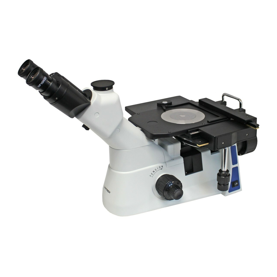
MEC4 INVERTED METALLURGICAL MICROSCOPE COMPONENTS DIAGRAM Metal Camera/Photo Stage Plate Port Carry Insert Extension Handle Stage Plate Mechanical Stage Eyepieces Stage Binocular Viewing Head Light Path Selection Slider On/Off Power Switch Tension Adjustment Collar X/Y Axis Coarse/Fine Focus Stage Control... -
Page 6: Component Diagrams
MEC4 INVERTED METALLURGICAL MICROSCOPE COMPONENTS DIAGRAM Nosepiece Field Objective Nosepiece Diaphragm Centering Ring Adjustment Levers Analyzer Field Aperture Power Diaphragm Diaphragm Jack Light Intensity Lever Lever Control Knob Coarse/Fine Focus Adjustment Knobs Condenser Adjustment Lever Illuminator Fuse Housing Holder UNITRON... -
Page 7: Assembly Diagram
MEC4 INVERTED METALLURGICAL MICROSCOPE ASSEMBLY DIAGRAM The diagram below shows how to assemble the various components. The numbers indicate the order of assembly. Use the 1.5mm and 2mm hex wrenches that are supplied with your microscope when required. Be sure to keep these wrenches for changing out components or making adjustments. -
Page 8: Detailed Assembly
MEC4 INVERTED METALLURGICAL MICROSCOPE ASSEMBLY Objectives (Fig. 1 & 2) To install the objectives: 1. Turn the coarse adjustment knob ① (Fig. 1) until the revolving nosepiece is at its lowest position. 2. Through the opening in the top of the stage, remove the nosepiece cap and thread the lowest magnification objective ②... - Page 9 (continued) Mechanical Stage and Extension Stage Plate (Fig. 3 & 4) The MEC4 comes with an attachable mechanical stage and an extension stage plate. Both mount underneath the stage platform with the provided thumb screws. To install the extension stage plate, gently and carefully lay the microscope on its side as shown (Fig. 3).
- Page 10 Fig. 6 Plug the power cord into a power supply receptacle. NOTE: Always use the power cord that came with your microscope. If your power cord becomes damaged or lost, please call your authorized UNITRON dealer for a replacement. UNITRON...
-
Page 11: Interpupillary Distance
MEC4 INVERTED METALLURGICAL MICROSCOPE OPERATION Plug the 3-prong line cord into the microscope and then into a grounded 120V or 220V A.C. electrical outlet. Usage of a surge suppressor outlet is highly recommended. Turn on “―” the power switch ① (Fig. 7). For longer bulb life always turn the illuminator variable intensity knob ②... -
Page 12: Operation Illumination
MEC4 INVERTED METALLURGICAL MICROSCOPE Operation (continued) Adjusting the Focusing Tension (Fig. 10) If the feel is very heavy when focusing with the focusing knobs ②③, or the specimen leaves the focus plane after focusing, adjust the tension with the tension adjustment ring ①. -
Page 13: Selecting The Light Path
MEC4 INVERTED METALLURGICAL MICROSCOPE Operation (continued) Selecting the Light Path (Fig. 13) The MEC4 is outfitted with a binocular viewing head with one photo port for HDMI/digital imaging. You must select the appropriate light path for observing specimens. The light path is set to 100% to the binocular eyepieces as the default setting at our facilities where the light path selection slider is set to the “OUT”... -
Page 14: Field Diaphragm
MEC4 INVERTED METALLURGICAL MICROSCOPE Operation (continued) Adjusting the Field Diaphragm (Fig. 14 & 15) By limiting the diameter of the light entering the condenser, the field diaphragm can prevent stray light ② and improve the image contrast. When the image is... -
Page 15: Condenser & Polarizer
MEC4 INVERTED METALLURGICAL MICROSCOPE Operation (continued) Condenser & Polarizer Adjustment (Fig. 16, 17 & 18) To adjust the light intensity, loosen the condenser lever ① by turning the knob on the condenser lever counterclockwise and then move the lever up or down. -
Page 16: Filters
To insert the filter slider into the filter slot on the MEC4, you must remove one of the end screws ④ (Fig. 21) by turning it counterclockwise. You may ②... -
Page 17: Mounting A Microscopy Camera (Optional)
MEC4 INVERTED METALLURGICAL MICROSCOPE Operation (continued) Mounting a Microscopy Camera (Optional) (Fig. 22) Camera Installing Couplers ② ④ Loosen the lock screw ① and remove the dust cap ② on the photo port ③. Loosen the lock screw ① until it is flush with the inside of the photo port. -
Page 18: Troubleshooting
MEC4 INVERTED METALLURGICAL MICROSCOPE TROUBLESHOOTING Under certain conditions, performance of this unit may be adversely affected by factors other than defects. If a problem occurs, please review the following list and take remedial action as needed. If you cannot solve the problem after checking the entire list, please contact your local dealer for assistance. -
Page 19: Troubleshooting
The lamp can’t light No power to the lamp you should need to replace the LED bulb, please contact an authorized UNITRON service center or call UNITRON at 1-888-289-2228 for an authorized service center near you. The light intensity adjustment knob is not set Adjust the light intensity adjustment knob. -
Page 20: Maintenance
United States of America. All items returned for warranty repair must be sent freight prepaid and insured to Unitron Ltd., 73 Mall Drive, Commack, NY 11725 – USA. All warranty repairs will be returned freight prepaid to any destination within the continental United States of America. For all foreign warranty repairs, return freight charges are the responsibility of the individual/company who returned the merchandise for repair.
Need help?
Do you have a question about the MEC4 and is the answer not in the manual?
Questions and answers