
Subscribe to Our Youtube Channel
Related Manuals for Unitron MEC2


Summary of Contents for Unitron MEC2
- Page 1 MEC2 INVERTED METALLURGICAL MICROSCOPE MANUAL 73 Mall Drive, Commack, NY 11725 • 631-543-2000 (P) • 631-589-6975 (F) www.unitronusa.com • info@unitronusa.com...
-
Page 2: Table Of Contents
MEC2 INVERTED METALLURGICAL MICROSCOPE CONTENTS SAFETY NOTES ........................3 CARE AND MAINTENANCE ....................3 INTRODUCTION ........................4 UNPACKING AND COMPONENTS ..................4 COMPONENT DIAGRAMS ....................4-5 ASSEMBLY .......................... 5 DETAILED ASSEMBLY PROCEDURE ................6 ADJUSMENT AND OPERATION TURNING ON THE LAMP ..................... 10 ADJUSTING THE BRIGHTNESS .................. -
Page 3: Safety Notes
A regular schedule of preventative ® maintenance by qualified personnel is highly recommended. Your authorized UNITRON distributor can arrange for this service. -
Page 4: Introduction
MEC2 INVERTED METALLURGICAL MICROSCOPE INTRODUCTION ® ® Congratulations on the purchase of your new UNITRON microscope. UNITRON microscopes are engineered and manufactured to the highest quality standards. Your microscope will last a lifetime if ® used and maintained properly. UNITRON microscopes are carefully assembled, inspected and tested by our staff of trained technicians in our New York facility. -
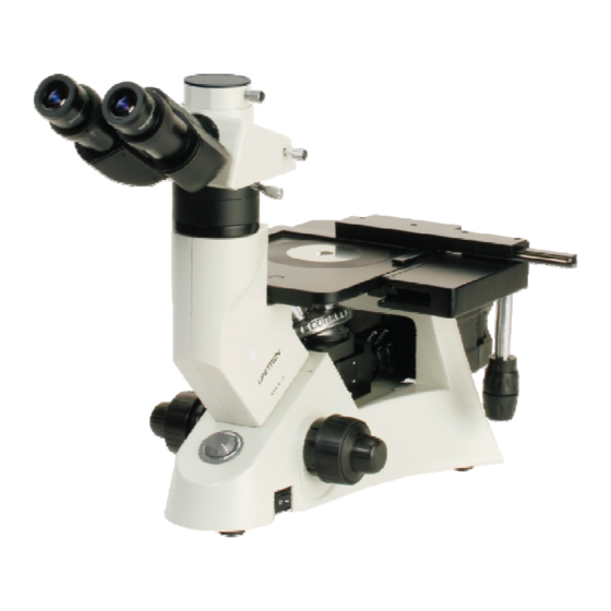
Page 5: Component Diagrams
MEC2 INVERTED METALLURGICAL MICROSCOPE COMPONENT DIAGRAMS (continued) Analyzer Aperture Field Filter Diaphragm Diaphragm Condenser Adjsutment Lever Polarizer ® UNITRON 73 Mall Drive, Commack, NY 11725 • 631-543-2000 • www.unitronusa.com... -
Page 6: Detailed Assembly Procedure
MEC2 INVERTED METALLURGICAL MICROSCOPE DETAILED ASSEMBLY PROCEDURE Attaching the Mechanical Stage And X-Y Controls The mechanical stage may be installed in either side of the stage to enlarge the stage surface. The x-y controls must be installed on the opposite side of theauxiliary stage. - Page 7 MEC2 INVERTED METALLURGICAL MICROSCOPE Insert the lamp gently but firmly into the socket. Do not touch the halogen bulb with bare fingers. Doing so will shorten the service life of the lamp. If you leave fingerprints on the lamp surface, clean it with a soft cloth or lint free paper.
- Page 8 MEC2 INVERTED METALLURGICAL MICROSCOPE Mounting Filters and Polarizer (Figure 10) 1. Insert a standard filter(s) into slot (1) 2. For polarized observation, insert the polarizer filter into slot (2). Standard filters are blue, yellow and green filters Fig. 9 Mounting the Analyzer (Figure 11) Insert the analyzer (3) into the slot under the trinocular viewing head.
- Page 9 MEC2 INVERTED METALLURGICAL MICROSCOPE Connecting the Power Cord (Figures 12, 13 & 14) The electric cord should never be bent, twisted, crushed or subjected to stress. 1. Set the main switch① to “O” (off) before connecting the power cord. 2. Insert the power cord into the receptacle②.
-
Page 10: Adjusment And Operation
MEC2 INVERTED METALLURGICAL MICROSCOPE ADJUSTMENT AND OPERATION Turning On The Lamp (Figure 15) Connect the power cord, then set the main switch① on the side of the base to the “on” position (“-”). Fig. 15 Adjusting The Brightness (Figure 16) Rotate the brightness adjustment knob (2) clockwise to increase the brightness. -
Page 11: Adjusting The Illumination
MEC2 INVERTED METALLURGICAL MICROSCOPE Adjusting the Illumination (Figure 18) 1. Make sure the field of view is bright and evenly illuminated, and has no filament shadow. If there is filament shadow, adjust the condenser adjustment knob③ to its proper position. -
Page 12: Placing And Moving The Specimen
MEC2 INVERTED METALLURGICAL MICROSCOPE Placing and Moving the Specimen (Figures 19 & 20) 1. Place the slide in the center of the stage and secure with the stage clip. 2. The specimen may be moved to different positions by turning the X-axis knob① and/or the Fig. -
Page 13: Adjusting The Diopter
MEC2 INVERTED METALLURGICAL MICROSCOPE Adjusting the Diopter (Figure 21) 1. Looking through the right ocular only with your right eye, use the coarse and fine focusing adjustment knobs to focus on the specimen. 2. Then with your left eye only, look through the left ocular. -
Page 14: Microscope Video And Photography
MEC2 INVERTED METALLURGICAL MICROSCOPE Light Path Illumination Application Selecting Lever Pushed In 100% for binocular observation Binocular observation Pulled Out 20% for binocular observation Binocular observation and video (CCTV) or microphotography simultaneously 80% for video or microphotography Polarization Observation 1. Insert the polarizer and analyzer as described on page 8 (Figures 10 & 11). - Page 15 MEC2 INVERTED METALLURGICAL MICROSCOPE Focusing (Figure 25) Observing through binocular position, focus the specimen until a sharp image is obtained. Then check the image on the monitor to which the microscope is connected. If the image is not sharp, rotate the video adapter (4) until the image is sharp.
-
Page 16: Specifications
MEC2 INVERTED METALLURGICAL MICROSCOPE SPECIFICATIONS Optical System Infinity Optical System Viewing Tube Siedentopf style; Trinocular Tube; Inclined 30º; Diopter Range: ±5; Interpupillary distance range: 48mm -75mm Standard configuration light distribution: Binocular 100% or Binocular/photo 20%/80% Eyepiece Extra Wide Field 10x with 20mm field of view with diopter adjustment and... -
Page 17: Troubleshooting
MEC2 INVERTED METALLURGICAL MICROSCOPE TROUBLESHOOTING Under certain conditions, performance of this unit may be adversely affected by factors other than defects. If a problem occurs, please review the following list and take remedial action as needed. If you cannot solve the problem after checking the entire list, please contact your local dealer for assistance. -
Page 18: Maintenance
UNITRON® distributor or UNITRON® at (631) 543-2000. This warranty is limited to the continental United States of America. All items returned for warranty repair must be sent freight prepaid and insured to Unitron Ltd., 73 Mall Drive, Commack, NY 11725 – USA. All warranty repairs will be returned freight prepaid to any destination within the continental United States of America.
Need help?
Do you have a question about the MEC2 and is the answer not in the manual?
Questions and answers