
Subscribe to Our Youtube Channel
Related Manuals for Unitron System 374


Summary of Contents for Unitron System 374
- Page 1 System 374 ZOOM STEREO MICROSCOPE MANUAL 73 Mall Drive, Commack, NY 11725 • 631-543-2000 (P) • 631-589-6975 (F) www.unitronusa.com • info@unitronusa.com...
-
Page 3: Table Of Contents
SYSTEM 374 STEREO MICROSCOPES CONTENTS SAFETY NOTES ........................3 CARE AND MAINTENANCE ....................3 INTRODUCTION ........................4 UNPACKING AND COMPONENTS ..................4 COMPONENT DIAGRAMS ....................4-5 ASSEMBLY .......................... 6 ASSEMBLING THE BALL BEARING BOOM STAND ............. 6 ASSEMBLING THE PLAIN STAND ................9 INSTALLING THE BEAM SPLITTER ................ -
Page 4: Safety Notes
A regular schedule of preventative maintenance by qualified service personnel is highly recommended. Your authorized UNITRON ® distributor can arrange for this service. -
Page 5: Introduction
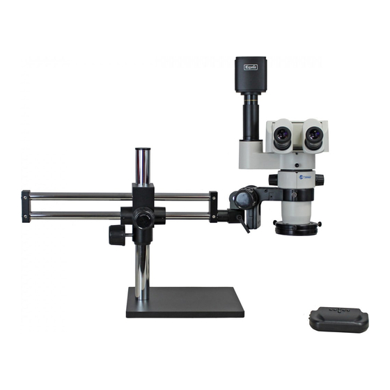
SYSTEM 374 STEREO MICROSCOPES INTRODUCTION Congratulations on the purchase of your new UNITRON ® microscope. UNITRON ® microscopes are engineered and manufactured to the highest quality standards. Your microscope will last a lifetime if used and maintained properly. UNITRON ®... - Page 6 SYSTEM 374 STEREO MICROSCOPES Excelis HD Camera Eyepieces Ergonomic Video Adapter Binocular Head Beam Splitter Zoom Body Focus Mount Focus Knob Plain Stand Lens/Objective Ring Light Ring Light Controller UNITRON ® 73 Mall Drive, Commack, NY 11725 • 631-543-2000 • www.unitronusa.com...
-
Page 7: Assembly
SYSTEM 374 STEREO MICROSCOPES ASSEMBLY The following photos show how to assemble the various modules in the order of assembly. When assembling the microscope, make sure that all parts are free of dust and dirt, and avoid scratching any parts or touching glass surfaces. - Page 8 SYSTEM 374 STEREO MICROSCOPES Place the base on the table and unscrew the cap on the vertical post. Insert the safety lock collar onto the vertical post and tighten/lock it using the clamp. 5. Slide the horizontal pillar with cross block into the vertical post.
- Page 9 SYSTEM 374 STEREO MICROSCOPES 7. Replace the cap back onto the vertical post. 8. Screw the lock lever on the end of the horizontal pillar. This lock lever secures the e-arm or focus mount. 9. Insert the e-arm or focus mount into the end of the horizontal bar and tighten using the lock lever.
-
Page 10: Assembling The Plain Stand
SYSTEM 374 STEREO MICROSCOPES 11. E-arm or focus mount can be inserted from the TOP, BOTTOM or HORIZONTALLY of the horizontal bar. Set e-arm or focus mount up at various angles and tighten the lock lever for oblique viewing. Ball Bearing Boom Stand assembly is complete. - Page 11 SYSTEM 374 STEREO MICROSCOPES Install the focus arm. Align the focus arm on the focus mount of the pillar as shown. Using the supplied hex key, attach the focus arm to the focus mount with the supplied hex screws. Plain Stand assembly is complete.
-
Page 12: Installing The Beam Splitter
SYSTEM 374 STEREO MICROSCOPES Installing the Beam Splitter 1. Place the beam splitter onto the top of the optical body by matching the groove of the of the beam splitter’s bottom and the securing screw of the optical body Tighten the screw to secure the optical body and the beam splitter. - Page 13 SYSTEM 374 STEREO MICROSCOPES Installing the Eyepieces 1. Remove the dust caps from the eyepiece tubes. 2. Insert the eyepieces into the eyepiece tube. Be sure to install the eyepieces all the way into the tube. 3. Set the eyepiece diopter scale for each eyepiece to 0.
-
Page 14: Adjustment And Operation
SYSTEM 374 STEREO MICROSCOPES ADJUSTMENT AND OPERATION Adjusting Binocular Viewing Head Adjusting Interpupillary Distance (Fig. 6) Different users have different interpupillary distances (this distance is between the centers of the pupils of each eye). When the operator of the microscope changes, it will be necessary to adjust the interpupillary distance. -
Page 15: Focus Adjustment
SYSTEM 374 STEREO MICROSCOPES Focus Adjustment Adjusting the Rotation Tension of the Focus Adjustment Knob (Fig. 8, Fig. 9) To adjust tension, hold both left and right focus adjustment knobs ① with both hands, hold the left knob (to prevent it from turning), and rotate... -
Page 16: Specifications
Visual Field (mm) Magnification (mm) 0.5X 4X – 25X 60 – 9.6 1.0X 8X – 50X 30 – 4.8 System 374 Trinocular Optical Data MAGNIFICATION* Accessory Magnification FOV (mm) with Magnification FOV (mm) with Working Distance Lens with Zoom @ 0.8 Zoom @ 0.8... -
Page 17: Troubleshooting
SYSTEM 374 STEREO MICROSCOPES TROUBLESHOOTING Under certain conditions, performance of this unit may be adversely affected by factors other than defects. If a problem occurs, please review the following list and take remedial action as needed. If you cannot solve the problem after checking the entire list, please contact your local dealer for assistance. -
Page 18: Maintenance
UNITRON® distributor or UNITRON® at (631) 543-2000. This warranty is limited to the continental United States of America. All items returned for warranty repair must be sent freight prepaid and insured to Unitron Ltd., 73 Mall Drive, Commack, NY 11725 – USA. All warranty repairs will be returned freight prepaid to any destination within the continental United States of America.
Need help?
Do you have a question about the System 374 and is the answer not in the manual?
Questions and answers